COPYRIGHT © JUNE, 2005 BY GRIZZLY INDUSTRIAL, INC. REVISED OCTOBER, 2007. (TR)
WARNING: NO PORTION OF THIS MANUAL MAY BE REPRODUCED IN ANY SHAPE
OR FORM WITHOUT THE WRITTEN APPROVAL OF GRIZZLY INDUSTRIAL, INC.
#TR7337
PRINTED IN CHINA
MODEL G3616/G3617
MILLING MACHINE
OWNER'S MANUAL


G3616/G3617 Mill 1
Table of Contents
INTRODUCTION ............................................................................................................................... 3
Foreword .................................................................................................................................... 3
Contact Info ................................................................................................................................
3
Identification ............................................................................................................................... 4
G3616 Machine Data Sheet .......................................................................................................
5
G3617 Machine Data Sheet .......................................................................................................
8
SECTION 1: SAFETY .....................................................................................................................
11
Safety Instructions for
Machinery ............................................................................................. 11
Additional Safety Instructions for Mills .....................................................................................
13
SECTION 2: CIRCUIT REQUIREMENTS ......................................................................................
14
110/220V Single-Phase ...........................................................................................................
14
Grounding ................................................................................................................................. 15
Extension Cords .......................................................................................................................
15
Rewiring to 110V ......................................................................................................................
15
SECTION 3: SET UP ......................................................................................................................
16
About This Section ...................................................................................................................
16
Items Needed for Set Up ......................................................................................................... 16
Unpacking ................................................................................................................................ 16
Inventory ................................................................................................................................... 17
Hardware Recognition Chart ....................................................................................................
18
Clean Up ..................................................................................................................................
19
Site Considerations ..................................................................................................................
19
Mounting to Floor .....................................................................................................................
19
Way Cover Installation .............................................................................................................
21
Handle Installation ....................................................................................................................
21
SECTION 4: OPERATION ..............................................................................................................
22
Operation Safety ......................................................................................................................
22
Setting RPM .............................................................................................................................
22
Turning Spindle
ON .................................................................................................................. 24
Loading Tools ...........................................................................................................................
25
Unloading Tools .......................................................................................................................
26
Spindle Head Positioning .........................................................................................................
26
Table Rotation .......................................................................................................................... 28
Vise Rotation ............................................................................................................................
28
Table Travel .............................................................................................................................
29
Quill Travel ...............................................................................................................................
30
Power Feed ..............................................................................................................................
30
Coolant S
ystem ........................................................................................................................ 31
Spindle Break-In Procedure .....................................................................................................
31
SECTION 5:
ACCESSORIES ......................................................................................................... 32
SECTION 6: MAINTENANCE ........................................................................................................
35
General ..................................................................................................................................... 35
Schedule .................................................................................................................................. 35
Cleaning ................................................................................................................................... 35
Unpainted Cast Iron .................................................................................................................
35
Lubrication ................................................................................................................................ 36
Checking/Adding Coolant .........................................................................................................
38
Changing Coolant .................................................................................................................... 38

2 G3616/G3617 Mill
SECTION 7: SERVICE ................................................................................................................... 39
About Service ...........................................................................................................................
39
Troubleshooting ........................................................................................................................ 40
Replacing V-belts .....................................................................................................................
42
Adjusting Gibs ..........................................................................................................................
44
G3616 Wiring Box Identification ............................................................................................... 45
G3616 110V Wiring Diagram ................................................................................................... 46
G3616 220V Wiring Diagram ................................................................................................... 47
G3617 Wiring Box Identification ............................................................................................... 48
G3617 110V Wiring Diagram ................................................................................................... 49
G3617 220V Wiring Diagram ................................................................................................... 50
Column Parts Breakdown ........................................................................................................
51
Column Parts List .....................................................................................................................
52
Rotary Table Parts Breakdown ................................................................................................
53
Rotary Table Parts List ............................................................................................................
54
Head Parts Brea
kdown ............................................................................................................ 55
Head Parts List .........................................................................................................................
56
G3617 Horizontal Spindle Parts Breakdown ............................................................................
57
G3617 Horizontal Spindle Parts List ........................................................................................
58
Power Feed Parts Breakdown .................................................................................................
59
Power Feed
Parts List .............................................................................................................. 60
Power Feed
Parts List, continued ............................................................................................ 61
G3616 Electrical Parts Breakdown ..........................................................................................
62
G3616 Electrical Parts List ....................................................................................................... 63
G3617 Electrical Parts Breakdown .......................................................................................... 64
G3617 Electrical Parts List .......................................................................................................
65
WARRANTY AND RETURNS ........................................................................................................ 66

G3616/G3617 Mill 3
Foreword
INTRODUCTION
Read the manual before
assembly and operation.
Serious personal injury
may result if safety or
operational information
is not understood or fol-
lowed.
NOTICE
This machine is designed for highly skilled
individuals who have an understanding of
metalworking. This manual instructs on the
assembly and controls of this machine, but
does not describe the skills and techniques
involved in crafting metal. If you are not an
experienced metalworker, additional infor-
mation sources are necessary to realize the
full potential of this machine. Classes, trade
journals, metalworking magazines, and your
local library are good places to start.
We are proud to offer the Model G3616/G3617
Mill. This machine is part of a growing Grizzly
family of fine metalworking machinery. When
used according to the guidelines set forth in this
manual, you can expect years of trouble-free,
enjoyable operation and proof of Grizzly’s com
-
mitment to customer satisfaction.
We are pleased to provide this manual with the
Model G3616/G3617. It was written to guide you
through assembly, review safety considerations,
and cover general operating procedures.
The specifications, drawings, and photographs
illustrated in this manual represent the Model
G3616/G3617 as supplied when the manual
was prepared. For your convenience, we always
keep current Grizzly manuals available on our
website at
www.grizzly.com. Any updates to
your machine will be reflected in these manuals
as soon as they are complete.
If you have any comments regarding this manual,
please write to us at the address below:
Grizzly Industrial, Inc.
c
/o Technical Documentation Manager
P.O. Box 2069
Bellingham, WA 98227-2069
We stand behind our machines. If you have any
service questions or parts requests, please call or
write us at the location listed below.
Grizzly Industrial, Inc.
1203 Lycoming Mall Circle
Muncy, PA 17756
Phone: (570) 546-9663
Fax: (800) 438-5901
E-Mail: [email protected]
Web Site: http://www.grizzly.com
Contact Info

4 G3616/G3617 Mill
S
Figure 1. The following is a list of controls and components on the Model G3616/G3617. Please take time
to become familiar with each term and its location. These terms will be used throughout the manual and
knowing them is essential to understanding the instructions and terminology used in this manual.
Identification
A
A. Vertical Spindle ON/OFF Switch
B. Coolant ON/OFF Switch
C. Vertical Spindle Speed Setting Chart
D. Vertical Quill Travel Lock
E. Vertical Spindle
F. Work Light
G. Coolant Hose
H. Longitudinal Feed Handwheel (2 Places)
I. Powerfeed Hard Stop (2 Places)
J. Longitudinal Feed Lock (2 Places)
K. Knee Feed Handwheel
L. Cross Feed Handwheel
M. Coolant Tray
N. Powerfeed Limit Switch
O. Emergency Stop
P. Horizontal Spindle ON/OFF
Q. Cross Feed Lock (2 Places)
R. Knee Feed Lock (2 Places)
S. Powerfeed Controls
T. Horizontal Spindle Speed Setting Chart
U. Access Cover for Horizontal Spindle Speed
Adjustment
V. Horizontal Spindle (G3617 only)
W. Quill Feed Handle and Lock
X. Micro-Feed Adjustment Handle
Y. Access Panel for Vertical Spindle Speed
Adjustment
B
C
D
E
F
G
H
I
J
K
L
M
N
O
P
Q
R
S
H
I
T
U
V
W
X
Y

G3616/G3617 Mill 5
The information contained herein is deemed accurate as of 10/1/2007 and represents our most recent product specifications.
Due to our ongoing improvement efforts, this information may not accurately describe items previously purchased.
PAGE 1 OF 3Model G3616
MACHINE DATA
SHEET
Customer Service #: (570) 546-9663 · To Order Call: (800) 523-4777 · Fax #: (800) 438-5901
MODEL G3616 VERTICAL MILL
Product Dimensions:
Weight............................................................................................................................................................ 1322 lbs.
Length/Width/Height...................................................................................................41-15/16 x 41-3/4 x 80-15/16 in.
Foot Print (Length/Width)....................................................................................................................... 28-3/4 x 18 in.
Shipping Dimensions:
Type........................................................................................................................................................... Wood Crate
Content............................................................................................................................................................ Machine
Weight............................................................................................................................................................ 1996 lbs.
Length/Width/Height............................................................................................................................. 44 x 45 x 88 in.
Electrical:
Switch................................................................................................................................................ Forward/Reverse
Switch Voltage...................................................................................................................................................... 220V
Cord Length............................................................................................................................................................
6 ft.
Cord Gauge....................................................................................................................................................12 gauge
Recommended Breaker Size................................................................................15 amps at 220V, 30 amps at 110V
Plug.......................................................................................................................................................................... No
Motors:
Main
Type.................................................................................................................. TEFC Capacitor Start Induction
Horsepower.................................................................................................................................................2 HP
Voltage.................................................................................................................................................
110/220V
Prewired......................................................................................................................................................220V
Phase........................................................................................................................................................ Single
Amps........................................................................................................................................................
20/10A
Speed.................................................................................................................................................1725 RPM
Cycle..........................................................................................................................................................
60 Hz
Number Of Speeds...........................................................................................................................................
1
Power Transfer ............................................................................................................................... V-Belt Drive
Bearings........................................................................................................ Shielded, Permanently Lubricated
Coolant
Type................................................................................................................................................... AC Sealed
Horsepower..............................................................................................................................................1/8 HP
Voltage.................................................................................................................................................110/220V
Prewired......................................................................................................................................................220V
Phase........................................................................................................................................................ Single
Amps....................................................................................................................................................0.9/0.45A
Cycle..........................................................................................................................................................60 Hz
Number Of Speeds...........................................................................................................................................
1
Power Transfer ................................................................................................................................Direct Drive
Bearings........................................................................................................ Shielded, Permanently Lubricated
G3616 Machine Data Sheet

6 G3616/G3617 Mill
The information contained herein is deemed accurate as of 10/1/2007 and represents our most recent product specifications.
Due to our ongoing improvement efforts, this information may not accurately describe items previously purchased.
PAGE 2 OF 3Model G3616
Main Specifications:
Operation Info
Spindle Travel.............................................................................................................................................. 5 in.
Swing..........................................................................................................................................................44 in.
Longitudinal Table Travel.....................................................................................................................15-1/2 in.
Cross Table Travel.................................................................................................................................8-1/2 in.
Vert. Table Travel.......................................................................................................................................13 in.
Table Swivel.................................................................................................................... Left and Right 45 deg.
Knee Travel................................................................................................................................................ 13 in.
Ram Travel.................................................................................................................................................11 in.
Ram Swivel Angle................................................................................................................................... 90 deg.
Head Travel..................................................................................................................................................5 in.
Head Swivel............................................................................................................................................ 90 deg.
Head Tilt.......................................................................................................................... Left and Right 90 deg.
Turret Or Column Swivel................................................................................................. Left and Right 90 deg.
Max. Dist Spindle To Column.....................................................................................................................22 in.
Max. Dist Spindle To Table........................................................................................................................ 15 in.
Drilling Cap For Cast Iron.......................................................................................................................1-1/4 in.
Drilling Cap For Steel............................................................................................................................. 1-1/4 in.
No. Of Vert. Spindle Speeds.............................................................................................................................
9
Range Of Vert. Spindle Speeds..................................... 270, 390, 490, 615, 860, 930, 1600, 1960, 2950 RPM
No. Of Longitudinal Feeds..................................................................................................................... Variable
Feed Rate.......................................................................................................................................
0 - 140 RPM
Quill Dia..................................................................................................................................................3-1/2 in.
Table Info
Table Length........................................................................................................................................ 31-1/2 in.
Table Width............................................................................................................................................ 9-1/2 in.
Table Thickness.....................................................................................................................................
2-1/2 in.
No. Of T Slots....................................................................................................................................................
3
T Slots Width......................................................................................................................................... 0.640 in.
T Slots Height...............................................................................................................................................1 in.
T Slots Centers...................................................................................................................................... 1-5/8 in.
Stud Size...................................................................................................................................................
1/2 in.
Lead Screw Info
Lead Screw Diameter...................................................................................................................................1 in.
Lead Screw TPI.................................................................................................................................................
5
Lead Screw Length.................................................................................................................................... 37 in.
Construction
Spindle Housing Const.........................................................................................................................
Cast Iron
Table Const................................................................................................................Surface Ground Cast Iron
Head Const...........................................................................................................................................
Cast Iron
Column Const.......................................................................................................................................Cast Iron
Base Const........................................................................................................................................... Cast Iron
Paint..........................................................................................................................................................
Epoxy
Other
Collars Calibrated..................................................................................................................................0.001 in.
Spindle Info
Spindle Taper................................................................................................................................................ R-8
End Milling Cap............................................................................................................................................ 1 in.
Face Milling Cap...........................................................................................................................................3 in.
Draw Bar Diameter................................................................................................................................0.550 in.
Draw Bar TPI...................................................................................................................................................20
Draw Bar Length.................................................................................................................................. 16-5/8 in.
Spindle Bearings..........................................................................................................................Roller and Ball
550
1800

G3616/G3617 Mill 7
The information contained herein is deemed accurate as of 10/1/2007 and represents our most recent product specifications.
Due to our ongoing improvement efforts, this information may not accurately describe items previously purchased.
PAGE 3 OF 3Model G3616
Other Specifications:
Country Of Origin ................................................................................................................................................China
Warranty ............................................................................................................................................................ 1 Year
Serial Number Location ........................................................................................................... Label on Head Casting
Assembly Time .......................................................................................................................................... 1-1/2 hours
Features:
Coolant System
Fine Down Feed
Reversing Switch
Longitudinal Power Feed
Work Light
Centralized Controls
Accessories Included:
Drill Chuck with Arbor
Milling Vise
Set of R-8 Collets

8 G3616/G3617 Mill
The information contained herein is deemed accurate as of 10/1/2007 and represents our most recent product specifications.
Due to our ongoing improvement efforts, this information may not accurately describe items previously purchased.
PAGE 1 OF 3Model G3617
MACHINE DATA
SHEET
Customer Service #: (570) 546-9663 · To Order Call: (800) 523-4777 · Fax #: (800) 438-5901
MODEL G3617 HORIZONTAL / VERTICAL MILL
Product Dimensions:
Weight............................................................................................................................................................ 2054 lbs.
Length/Width/Height.................................................................................................................54-7/8 x 59 x 80-3/4 in.
Foot Print (Length/Width)................................................................................................................. 35-5/8 x 20-1/2 in.
Shipping Dimensions:
Type........................................................................................................................................................... Wood Crate
Content............................................................................................................................................................ Machine
Weight............................................................................................................................................................ 2429 lbs.
Length/Width/Height............................................................................................................................. 53 x 45 x 88 in.
Electrical:
Switch................................................................................................................................................ Forward/Reverse
Switch Voltage...................................................................................................................................................... 220V
Cord Length............................................................................................................................................................
6 ft.
Cord Gauge....................................................................................................................................................12 gauge
Recommended Breaker Size................................................................................15 amps at 220V, 30 amps at 110V
Plug.......................................................................................................................................................................... No
Motors:
Vertical
Type.......................................................................................................................... TEFC Capacitor Start/Run
Horsepower.................................................................................................................................................2 HP
Voltage.................................................................................................................................................
110/220V
Prewired......................................................................................................................................................220V
Phase........................................................................................................................................................ Single
Amps........................................................................................................................................................
20/10A
Speed.................................................................................................................................................1725 RPM
Cycle..........................................................................................................................................................
60 Hz
Number Of Speeds...........................................................................................................................................
1
Power Transfer .........................................................................................................................................V-Belt
Bearings........................................................................................................ Shielded, Permanently Lubricated
Horizontal
Type.......................................................................................................................... TEFC Capacitor Start/Run
Horsepower...........................................................................................................................................1-1/2 HP
Voltage.................................................................................................................................................110/220V
Prewired......................................................................................................................................................220V
Phase........................................................................................................................................................ Single
Amps..........................................................................................................................................................16/8A
Speed.................................................................................................................................................1725 RPM
Cycle..........................................................................................................................................................60 Hz
Number Of Speeds...........................................................................................................................................
1
Power Transfer .........................................................................................................................................V-Belt
Bearings........................................................................................................ Shielded, Permanently Lubricated
G3617 Machine Data Sheet

G3616/G3617 Mill 9
The information contained herein is deemed accurate as of 10/1/2007 and represents our most recent product specifications.
Due to our ongoing improvement efforts, this information may not accurately describe items previously purchased.
PAGE 2 OF 3Model G3617
Coolant
Type................................................................................................................................................... AC Sealed
Horsepower..............................................................................................................................................1/8 HP
Voltage.................................................................................................................................................110/220V
Prewired......................................................................................................................................................220V
Phase........................................................................................................................................................ Single
Amps....................................................................................................................................................0.9/0.45A
Cycle..........................................................................................................................................................60 Hz
Number Of Speeds...........................................................................................................................................
1
Power Transfer ................................................................................................................................Direct Drive
Bearings........................................................................................................ Shielded, Permanently Lubricated
Main Specifications:
Operation Info
Spindle Travel.............................................................................................................................................. 5 in.
Swing..........................................................................................................................................................54 in.
Longitudinal Table Travel........................................................................................................................... 22 in.
Cross Table Travel.................................................................................................................................8-1/2 in.
Vert. Table Travel.......................................................................................................................................13 in.
Table Swivel.................................................................................................................... Left and Right 45 deg.
Knee Travel................................................................................................................................................
13 in.
Ram Travel.................................................................................................................................................11 in.
Ram Swivel Angle................................................................................................................................... 90 deg.
Head Travel..................................................................................................................................................
5 in.
Head Swivel............................................................................................................................................ 90 deg.
Head Tilt..........................................................................................................................
Left and Right 90 deg.
Turret Or Column Swivel................................................................................................. Left and Right 90 deg.
Max. Dist Spindle To Column.....................................................................................................................27 in.
Max. Dist Spindle To Table..................................................................................................................
13-3/4 in.
Drilling Cap For Cast Iron.......................................................................................................................1-1/4 in.
Drilling Cap For Steel............................................................................................................................. 1-1/4 in.
Max. Dist Horz. Spindle Center To Table.............................................................................................11-3/8 in.
No. Of Vert. Spindle Speeds.............................................................................................................................
9
Range Of Vert. Spindle Speeds.....................................
270, 390, 490, 615, 860, 930, 1600, 1960, 2950 RPM
No. Of Horz. Spindle Speeds............................................................................................................................
8
Range Of Horz. Spindle Speeds.................................................. 72, 170, 210, 240, 290, 550, 830, 1300 RPM
No. Of Longitudinal Feeds..................................................................................................................... Variable
Feed Rate....................................................................................................................................... 0 - 140 RPM
Quill Dia..................................................................................................................................................3-1/2 in.
Table Info
Table Length........................................................................................................................................ 39-3/8 in.
Table Width............................................................................................................................................ 9-1/2 in.
Table Thickness.....................................................................................................................................
2-1/2 in.
No. Of T Slots....................................................................................................................................................
3
T Slots Width.........................................................................................................................................
0.640 in.
T Slots Height...............................................................................................................................................1 in.
T Slots Centers.............................................................................................................................................3 in.
Stud Size................................................................................................................................................... 1/2 in.
Lead Screw Info
Lead Screw Diameter...................................................................................................................................1 in.
Lead Screw TPI.................................................................................................................................................
5
Lead Screw Length.................................................................................................................................... 43 in.

10 G3616/G3617 Mill
The information contained herein is deemed accurate as of 10/1/2007 and represents our most recent product specifications.
Due to our ongoing improvement efforts, this information may not accurately describe items previously purchased.
PAGE 3 OF 3Model G3617
Construction
Spindle Housing Const......................................................................................................................... Cast Iron
Table Const................................................................................................................Surface Ground Cast Iron
Head Const...........................................................................................................................................Cast Iron
Column Const.......................................................................................................................................Cast Iron
Base Const........................................................................................................................................... Cast Iron
Paint.......................................................................................................................................................... Epoxy
Other
Collars Calibrated..................................................................................................................................0.001 in.
Spindle Info
Spindle Taper................................................................................................................................................ R-8
End Milling Cap............................................................................................................................................ 1 in.
Face Milling Cap...........................................................................................................................................3 in.
Draw Bar Diameter................................................................................................................................0.550 in.
Draw Bar TPI...................................................................................................................................................20
Draw Bar Length.................................................................................................................................. 16-5/8 in.
Spindle Bearings..........................................................................................................................Roller and Ball
Horz. Spindle Taper..................................................................................................................................... R-8
Horz. Spindle Sizes............................................................................................................................1, 1-1/4 in.
Horz. Spindle Bearing Type..........................................................................................................................
Ball
Other Specifications:
Country Of Origin ................................................................................................................................................China
Warranty ............................................................................................................................................................ 1 Year
Serial Number Location ........................................................................................................... Label on Head Casting
Assembly Time .......................................................................................................................................... 1-1/2 hours
Features:
Coolant System
Longitudinal, Variable Speed Power Feed
Work Light
Centralized Motor Controls
Accessories Included:
Drill Chuck with Arbor
Milling Vise
Set of R-8 Collets

G3616/G3617 Mill 11
SECTION 1: SAFETY
For Your Own Safety Read Instruction
Manual Before Operating This Equipment
Indicates an imminently hazardous situation which, if not avoided,
WILL result in death or serious injury.
Indicates a potentially hazardous situation which, if not avoided,
COULD result in death or serious injury.
Indicates a potentially hazardous situation which, if not avoided,
MAY result in minor or moderate injury. It may also be used to
alert against unsafe practices.
This symbol is used to alert the user to useful information about
proper operation of the equipment.
The purpose of safety symbols is to attract your attention to possible hazardous conditions. This
manual uses a series of symbols and signal words which are intended to convey the level of
importance of the safety messages. The progression of symbols is described below. Remember
that safety messages by themselves do not eliminate danger and are not a substitute for proper
accident prevention measures.
NOTICE
4. ALWAYS WEAR AN ANSI APPROVED
RESPIRATOR WHEN OPERATING
MACHINERY THAT PRODUCES DUST.
Wood dust is
a carcinogen and can cause
cancer and severe respiratory illnesses.
5. ALWAYS USE HEARING PROTECTION
WHEN
OPERATING MACHINERY.
Machinery noise can cause permanent
hearing damage.
6. WEAR PROPER APPAREL. DO NOT
wear loose clothing, gloves, neckties, rings,
or jewelry which may get caught in moving
parts. Wear protective hair covering to con
-
tain long hair and wear non-slip footwear.
1. READ THROUGH THE ENTIRE MANUAL
BEFORE STARTING MACHINERY.
Machinery presents serious injury hazards
to untrained users.
2. MAKE SURE ALL GUARDS ARE IN
THEIR CORRECT PLACE AND
WORK CORRECTLY BEFORE USING
MACHINERY. NEVER OPERATE
MACHINE WITHOUT GUARDS.
3. ALWAYS USE ANSI APPROVED
SAFETY GLASSES WHEN OPERATING
MACHINERY. Everyday eyeglasses only
have impact resistant lenses, they are
NOT safety glasses.
Safety Instructions for Machinery

12 G3616/G3617 Mill
7. NEVER OPERATE MACHINERY WHEN
TIRED, OR UNDER THE INFLUENCE OF
DRUGS OR ALCOHOL. Be mentally alert
at all times when running machinery.
8. BEWARE WOOD DUST ALLERGIES.
Certain woods may cause an allergic reac
-
tion in people and animals, especially
when exposed to fine dust. Make sure you
know what type of wood dust you will be
exposed to and always wear and ANSI
approved respirator.
9. ONLY ALLOW TRAINED AND PROP-
ERLY SUPERVISED PERSONNEL TO
OPERATE MACHINERY. Make sure oper
-
ation instructions are safe and clearly
understood.
10. KEEP CHILDREN AND VISITORS AWAY.
Keep all children and visitors a safe dis-
tance from the work area.
11. MAKE WORKSHOP CHILD PROOF. Use
padlocks, master switches, and remove
start switch keys.
12. NEVER LEAVE WHEN MACHINE IS
RUNNING. Turn power OFF and allow all
moving parts to come to a complete stop
before leaving machine unattended.
13. DO NOT USE IN DANGEROUS
ENVIRONMENTS. DO NOT use machin-
ery in damp, wet locations, or where any
flammable or noxious fumes may exist.
14. KEEP WORK AREA CLEAN AND WELL
LIT. Clutter and dark shadows may cause
accidents.
15. USE A GROUNDED EXTENSION CORD
RATED FOR THE MACHINE AMPERAGE.
Undersized cords overheat and reduce
voltage. Replace extension cords if they
become damaged. DO NOT use extension
cords for 220V machinery.
Safety Instructions for Machinery
16.
ALWAYS DISCONNECT FROM POWER
SOURCE BEFORE SERVICING
MACHINERY. Make sure switch is in OFF
position before reconnecting.
17. MAINTAIN MACHINERY WITH CARE.
Keep blades sharp and clean for best and
safest performance. Follow instructions for
lubricating and changing accessories.
18. REMOVE ADJUSTING KEYS AND
WRENCHES. Make a habit of checking for
keys and adjusting wrenches before turn
-
ing ON machinery.
19. CHECK FOR DAMAGED PARTS
BEFORE USING MACHINERY. Check
for binding and alignment of parts, broken
parts, part mounting, loose bolts, and any
other conditions that may affect machine
operation. Repair or replace damaged
parts.
20. USE RECOMMENDED ACCESSORIES.
Refer to the instruction manual for recom
-
mended accessories. The use of improper
accessories may cause risk of injury.
21. DO NOT FORCE MACHINERY. Work at
the speed for which the machine or acces
-
sory was designed.
22. SECURE WORKPIECE. Use clamps or
a vise to hold the workpiece when practi
-
cal. A secured workpiece protects your
hands and frees both hands to operate the
machine.
23. DO NOT OVERREACH. Keep proper foot
-
ing and balance at all times.
24. MANY MACHINES WILL EJECT THE
WORKPIECE TOWARD THE OPERATOR.
Know and avoid conditions that cause the
workpiece to be ejected.
25. ALWAYS LOCK MOBILE BASES
BEFORE OPERATING MACHINERY
.

G3616/G3617 Mill 13
Additional Safety Instructions for Mills
Like all power tools, there is danger asso-
ciated with the Model G3616/G3617 Mill.
Accidents are frequently caused by lack
of familiarity or failure to pay attention.
Use this tool with respect and caution to
lessen the possibility of operator injury. If
normal safety precautions are overlooked
or ignored, serious personal injury may
occur.
No list of safety guidelines can be complete.
Every shop environment is different. Always
consider safety first, as it applies to your
individual working conditions. Use this and
other machinery with caution and respect.
Failure to do so could result in serious per-
sonal injury, damage to equipment or poor
work results.
10. UNSECURE BITS/CUTTERS. Be sure drill
bit is securely locked in the chuck or cut
-
ter has been secured in a holder or collet
before turning the mill
ON.
11. DAMAGED MACHINE. Never operate mill
if any part is damaged or broken until it is
properly repaired or replaced.
12. PROPER CLEA
RANCE. Be sure cutter,
workpiece and machine parts have proper
working clearance throughout the range of
motion you intend to use.
13. FINGER PROXIMITY. Never place your fin-
gers in a position where drill or cutter could
contact them if a part shifts unexpectedly.
Serious personal injury could result.
14. ADJUSTMENTS DURING OPERATION.
Never perform layout, assembly, or setup
work on the mill while a bit or cutter is rotat
-
ing.
15. LEAVING MACHINE.
Shut off power,
remove drill or cutting tool, and clean tool
before leaving machine.
16. EXPERIENCING DIFFICULTIES. If at any
time you are experiencing difficulties per
-
forming the intended operation, stop using
the machine!
Then contact our Technical
Support or ask a qualified expert how the
operation should be performed.
1. SETUP. Do not use until mill is completely
setup according to this instruction manual.
2. OPERATOR UNDERSTANDING. Do not
use the mill until all controls and adjust
-
ments are understood.
3. ADJUSTMENT TOOLS. Ensure that all
wrenches and adjusting keys have been
removed before starting machine.
4. CORRECT SPEEDS. Always use the rec-
ommended speeds
and feeds with milling
cutters and router bits.
5. DEPTH STOP. Adjust depth stop to prevent
drilling into table work surface.
6. CLEAN WORK AREA. Keep area around
the mill free from oil, tools, and chips.
7. HOLDING WORKPIECES. Never hold
workpieces with your hands during milling
or drilling. Instead, clamp it to the table
or use a vise bolted to the table to secure
workpiece and prevent rotation.
8. HANDLING SHARP CUTTERS
. Never
handle sharp cutt
ers with bare hands. Paper
towels or shop rags wrapped around them
will help to avoid injury.
9. CLEANING OFF SHAVINGS. Always use
a brush—not a rag—to remove metal shav
-
ings or chips.

14 G3616/G3617 Mill
SECTION 2: CIRCUIT REQUIREMENTS
Serious personal injury could occur if you
connect the machine to the power source
before you have completed the set up pro
-
cess. DO NOT connect the machine to the
power source until instructed to do so.
110/220V Single-
Phase
The Model G3616/G3617 Horizontal/Vertical Mill
has two 110/220V single-phase motors. Both
motors come prewired for 220V operation, which
is the preferred power supply for the Model
G3616/G3617. Only one motor will ever operate
at a time, so the circuit requirements below are for
the vertical spindle motor, which has the highest
amp draw.
Amperage Draw
The 2 HP vertical spindle motor on the Model
G3616/G3617 is the largest motor on the machine
and it will draw the following amps, when com
-
bined with the coolant pump motor:
220V Connection ................................10.9 Amps
110V Connection ..............................20.45 Amps
Circuit Breaker Requirements
Install your machine on a dedicated circuit to
reduce the possibility of tripping the circuit break
-
er. If the circuit breaker frequently trips, have the
circuit inspected by a qualified electrician. Never
use a larger circuit breaker than stated below, or
you will increase the risk of fire.
220V Circuit Breaker .............................15 Amps
110V Circuit Breaker .............................25 Amps
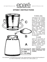
Figure 2. 6-15 plug and receptacle.
Figure 3. 5-30 plug and receptacle.
Plug Type
The cord set enclosed does not have a plug as the
style of plug you require will depend upon the type
of service you currently have or plan to install. We
recommend using the following plug and recep
-
tacles (see Figures
2 & 3 for examples):
220V Plug & Receptacle ..............................
6-15
110V Plug & Receptacle ..............................
5-30

G3616/G3617 Mill 15
In the event of an electrical short, grounding
reduces the risk of electric shock. This tool is
equipped with a power cord that has a grounding
wire, which must be properly connected to the
grounding prong on the plug; likewise, the outlet
must be properly installed and grounded as well.
All electrical connections must be made in accor-
dance with local codes and ordinances.
Grounding
This machine must have a ground prong in
the plug to help ensure that it is grounded.
DO NOT remove ground prong from plug
to fit into a two-pronged outlet! If the plug
will not fit the outlet, have the proper outlet
installed by a qualified electrician.
Electrocution or fire could
result if this machine is
not grounded correctly or
if your electrical configu
-
ration does not comply
with local and state codes.
Ensure compliance by
checking with a licensed
electrician!
220V Operation
We do not recommend the use of extension cords
on 220V equipment. Instead, arrange the place
-
ment of your equipment and the installed wiring to
eliminate the need for extension cords.
110V Operation
If you find it necessary to use a 110V extension
cord:
• Make sure the cord is rated Standard Service
(grade S) or better.
• The extension cord must contain a ground
wire and plug pin.
• Use at least a 12 gauge cord that is 50 feet
long or less.
Extension Cords
Regardless of these instructions, all rewiring must
be performed/inspected by a qualified electrician
before placing the machine into operation.
Before starting, you must order the 110V conver
-
sion kit available for your machine. (G7947 110V
kit is #P7947600; G7948 110V conversion kit is
#P7948600.
To rewire the G3616/G3617 for 110V:
1. Rewire the spindle motor(s) and the coolant
motor as shown on the junction box cover on
each motor.
2. Replace the spindle motor relay(s) and the
coolant motor relay in the electrical control
box (see Pages 45 & 48) with the relays from
the conversion kit. Use the dial settings given
on Page to set the relays.
3. Change the 220V wire on the transformer to
110V.
Rewiring to 110V

16 G3616/G3617 Mill
The Model G3616/G3617
is a heavy machine.
Serious personal injury
may occur if safe mov
-
ing methods are not fol
-
lowed. To be safe, you
will need assistance and
power equipment when
moving the shipping
crate and removing the
machine from the crate.
The Model G3616/G3617 was carefully packed
when it left our warehouse. If you discover the
machine is damaged after you have signed
for delivery, please immediately call Customer
Service at (570) 546-9663
for advice.
Save the containers and all packing materials for
possible inspection by the carrier or its agent.
Otherwise, filing a freight claim can be difficult.
When you are completely satisfied with the con
-
dition of your shipment, you should inventory the
contents.
The purpose of this section is to guide you
through the required steps to get your machine
out of its crate and into operating condition.
Wear safety glasses dur-
ing the entire set up pro
-
cess!
This machine presents
serious injury hazards
to untrained users. Read
through this entire manu
-
al to become familiar with
the controls and opera
-
tions before starting the
machine!
Unpacking
About This Section
SECTION 3: SET UP
The following items are needed to complete the
set up process, but are not included with your
machine:
Description Qty
• Flat Head Screwdriver ................................ 1
• Phillips Screwdriver, short handle ..............
1
• Safety Glasses (for each person) ..............
1
• 19mm Open-ended Wrench .......................
1
• Solvent (for cleaning) .........................
Varies
• Shop rags (for cleaning) .....................
Varies
Items Needed for
Set Up

G3616/G3617 Mill 17
Inventory
After the crate has been removed, you will find
one wooden box, one tool box, one way cover,
and one wrench, all attached to the base of the
crate. A vise, with swivel base, is attached to the
table of the mill.
After all the parts have been
removed from the two boxes, you should have the
following items:
Figure 4. Wooden box and on-crate items.
Figure 5. Toolbox items.
In the event that any nonproprietary parts are
missing (e.g. a nut or a washer), we would be
glad to replace them, or for the sake of expedi
-
ency, replacements can be obtained at your local
hardware store.
Tool Box (Figure
5 & 6)
Qty
A. Tool Box ..................................................... 1
B. Drill Chuck, w/Key 1-16mm JT33 ............... 1
C. Handwheel Handles ................................... 3
D. Drift Key ...................................................... 1
E. Hex Wrench ................................................ 1
F. Wrench 21/24mm ...................................... 1
G. R8 - MT2 Adaptor ....................................... 1
H. R8 - MT3 Adaptor ....................................... 1
I. R8 - JT33 Adaptor ...................................... 1
J. One set R8 collets .................................... 13
includes: ....................
1
⁄8,
3
⁄16,
1
⁄4,
5
⁄16,
3
⁄8,
7
⁄16,
.............................
1
⁄2,
9
⁄16,
5
⁄8,
11
⁄16,
3
⁄4,
13
⁄16,
7
⁄8
K. Knee Handle ............................................... 1
Wooden Box/On-Crate Items (Figure
4)
Qty
A. Horizontal Arbor 1
1
⁄4" (G3617 only) ............ 1
B. Horizontal Arbor 1" (G3617 only) ............... 1
C. Way Cover .................................................. 1
D. Vertical Drawbar ......................................... 1
E. Horizontal Drawbar (G3617 Only) .............. 1
F. Wrench ....................................................... 1
Figure 6. Knee handle shown on mill.
A
B
C
D
E
A
J
H
I
G
B
C
D
E
F
K
F

18 G3616/G3617 Mill
Hardware Recognition Chart
Page is loading ...
Page is loading ...
Page is loading ...
Page is loading ...
Page is loading ...
Page is loading ...
Page is loading ...
Page is loading ...
Page is loading ...
Page is loading ...
Page is loading ...
Page is loading ...
Page is loading ...
Page is loading ...
Page is loading ...
Page is loading ...
Page is loading ...
Page is loading ...
Page is loading ...
Page is loading ...
Page is loading ...
Page is loading ...
Page is loading ...
Page is loading ...
Page is loading ...
Page is loading ...
Page is loading ...
Page is loading ...
Page is loading ...
Page is loading ...
Page is loading ...
Page is loading ...
Page is loading ...
Page is loading ...
Page is loading ...
Page is loading ...
Page is loading ...
Page is loading ...
Page is loading ...
Page is loading ...
Page is loading ...
Page is loading ...
Page is loading ...
Page is loading ...
Page is loading ...
Page is loading ...
Page is loading ...
Page is loading ...
Page is loading ...
Page is loading ...
Page is loading ...
Page is loading ...
/