
BEFORE YOU BEGIN
Read these instructions completely and carefully.
•
IMPORTANT – Save these instructions for local
electrical inspector’s use.
•
IMPORTANT – Observe all governing codes and
ordinances.
•
Install the clothes dryer according to the manufacturer’s
instructions and local codes.
•
Note to Installer – Be sure to leave these instructions
with the Consumer.
•
Note to Consumer – Keep these instructions for future
reference.
•
Clothes dryer installation must be performed by a
qualified installer.
•
This dryer must be exhausted to the outdoors.
•
Before the old dryer is removed from service or
discarded, remove the dryer door.
•
Service information and the wiring diagram are located
in the control console.
•
Do not allow children on or in the appliance. Close
supervision of children is necessary when the appliance
is used near children.
•
Proper installation is the responsibility of the installer.
•
Product failure due to improper installation is not
covered under the Warranty
.
• Install the dryer where the temperature is above 50°F
for satisfactory operation of the dryer control system.
• Remove and discard existing plastic or metal foil duct
and replace with UL-listed duct.
Questions? Call GE Appliances at 800.GE.CARES (800.432.2737) or visit our Web site at: GEAppliances.com
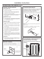
- Fire Hazard
WARNING
• Clothes dryer installation must be performed by a
qualified installer.
•
Install the clothes dryer according to these
instructions and local codes.
•
DO NOT install a clothes dryer with flexible plastic
venting materials. If flexible metal (semi-rigid or
foil-type) duct is installed, it must be UL-listed and
installed in accordance with the instructions found
in “Connecting the Dryer to House Vent” later in
this manual. Flexible venting materials are known
to collapse, be easily crushed and trap lint. These
conditions will obstruct dryer airflow and increase
the risk of fire.
•
DO NOT install or store this appliance in any
location where it could be exposed to water or
weather.
•
To reduce the risk of severe injury or death, follow
all installation instructions.
•
Save these instructions. (Installers: Be sure to leave
these instructions with the customer.)
Installation Dryers
Instructions
04
31-16769-3 08-16 GEA
234D2274P004
Printed in Mexico
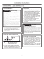
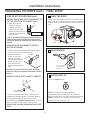
IN THE COMMONWEALTH OF
MASSACHUSETTS, THE FOLLOWING
INSTALLATION INSTRUCTIONS APPLY:
• Installation must be performed by a qualified
or licensed contractor, plumber, or gasfitter
qualified or licensed by the State.
•
If using a ball valve, it shall be a T-handle type.
•
A flexible gas connector, when used, must not
exceed 3 feet.
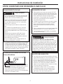
FOR GAS DRYERS ONLY

4.4”
(11.2 cm)
5.4”
(13.7 cm)
Installation Instructions
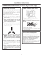
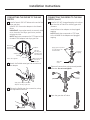
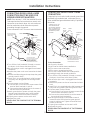
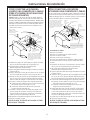
Tilt the dryer sideways and remove the foam
shipping pads by pulling at the sides and breaking
them away from the dryer legs. Be sure to remove all
of the foam pieces around the legs.
Remove the bag containing the literature.
UNPACKING YOUR DRYER
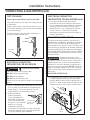
POWER CORDS:
GE Appliances strongly recommends the use of factory
specified parts. Select the power cord to fit your installation
requirements.
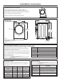
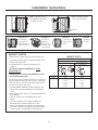
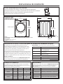
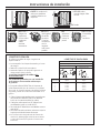
ROUGH-IN
DIMENSIONS
Side View
Front View
NOTE:
Dryer height can be adjusted to match washer height
With Pedestal: 52.1” (132.33 cm)
Stacked: 84” (213.36 cm)
33” (83.8 cm)
39.3”
(99.8cm)
27”
(68.6 cm)
2
39.3”
(99.8 cm)
GE Appliances strongly recommends the use of factory
specified parts. These hoses are manufactured and tested to
meet GE Appliances specifications.
GE Appliances strongly recommends the use of new water supply
hoses. Hoses degrade over time and need to be replaced every 5
years to reduce the risk of hose failures and water damage.
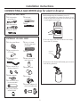
Parts and Accessories
Order on-line at GEApplianceParts.com, 24 hours a day or
by phone at 800.626.2002 during normal business hours.
STEAM WATER HOSES (for steam dryer models only):
Part Number Type Length Amperage
WX9X2 3-Prong 4 Feet 30
WX9X3 3-Prong 5 Feet 30
WX9X4 3-Prong 6 Feet 30
WX9X18 4-Prong 4 Feet 30
WX9X19 4-Prong 5 Feet 30
WX9X20 4-Prong 6 Feet 30
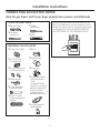
ACCESSORIES:
Order on-line at GEApplianceParts.com, 24 hours a day or
by phone at 800.626.2002 during normal business hours.
Part Number Accessory
SBSD137HWW
27” width White Pedestal
SBSC137HDG
27” width Diamond Gray Pedestal
GEFLSTACK Stacking Kit for Dryer over Washer
PM08X10085
Flexible Metal Dryer Transition Duct
WE01X20677
Clothes Dryer Shoe Rack
Part Number
Accessory
WE25X20060
Complete Kit (hoses, Y-adapter, washers) or
WE49X25794
Kit (Short hose, Y-adapter, washers) and
WE1M847
Long Hose
OR SEPARATELY
WE1M847
Long Hose and
WE1M848 Short Hose

Installation Instructions
MOBILE OR MANUFACTURED HOME
INSTALLATION
3
• Installation MUST conform to the
MANUFACTURED HOME CONSTRUCTION AND
SAFETY STANDARD, TITLE 24, PART 32–80 or
Standard CAN/CSA-Z240 MH, or, when such
standard is not applicable, with AMERICAN
NATIONAL STANDARD FOR MOBILE HOME,
ANSI/NFPA NO. 501B.
•
The dryer MUST be vented to the outdoors.
•
The exhaust vent MUST be securely fastened to
a non-combustible portion of the mobile home.
•
The vent MUST NOT be terminated beneath a
mobile or manufactured home.
•
The vent duct material MUST BE METAL.
•
KIT 14-D346-33 MUST be used to attach the dryer
securely to the structure.
•
The vent MUST NOT be connected to any other
duct, vent or chimney.
•
DO NOT use sheet metal screws or other
fastening devices which extend into the interior
of the exhaust vent.
•
Provide an opening with a free area of at least
25 square inches for introduction of outside air
into the dryer room.
•
See the sections for electrical connection
information.
REQUIREMENTS FOR ALCOVE OR
CLOSET INSTALLATION
- Explosion Hazard
WARNING
Keep flammable materials and vapors, such as gasoline,
away from dryer.
Place dryer at least 18” (46 cm) above the floor for a
garage installation.
Failure to do so can result in death, explosion, or fire.
• The dryer MUST be vented to the outdoors. See
the EXHAUSTING THE DRYER section.
•
Minimum clearance between dryer cabinet and
adjacent walls or other surfaces is:
0” either side
1” front
1” rear
1” top
•
Consideration must be given to provide adequate
clearance for installation and service.
•
Closet doors must be louvered or otherwise
ventilated and have at least 60 square inches of
open area. If the closet contains both a washer
and a dryer, doors must contain a minimum of
120 square inches of open area.
NOTE: WHEN THE EXHAUST DUCT IS LOCATED IN
THE REAR OF THE DRYER, THE CONFIGURATION OF
THE DUCTING MAY REQUIRE GREATER THAN 1” OF
REAR CLEARANCE.
Gas Dryers Only:
•
No other fuel burning appliance shall be installed
in the same closet as a gas dryer.
•
The dryer must be disconnected from the gas
supply piping during pressure testing at pressures
greater than ½ psi (3.5 kPa).
•
A 1/8 inch NPT minimum plugged tapping,
accessible for test gauge connection, must be
installed immediately upstream of the gas supply
connection to the dryer.
MINIMUM CLEARANCE OTHER THAN
ALCOVE OR CLOSET INSTALLATION
Minimum clearance to combustible surfaces and
for air opening are:
0” both sides; 1” rear; 1” top
.
Consideration must be given to provide adequate
clearance for installation and service.

4
Installation Instructions
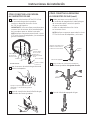
CONNECTING INLET HOSES (for steam dryer models only)
CONNECTING INLET HOSES (cont.)
7. Using pliers, tighten all the couplings with an
additional two–thirds turn.
NOTE: Do not overtighten. Damage to the couplings
may result.
8. Turn the water faucet on.
9. Check for leaks around the ‘’Y’’ connector, faucet
and hose couplings.
WATER SUPPLY REQUIREMENTS
Hot and cold water faucets MUST be installed
within 42 in. (107 cm) of your washer’s water
inlet. The faucets MUST be 3/4 in. (1.9 cm) garden
hose-type so inlet hoses can be connected. Water
pressure MUST be between 10 and 120 pounds
per square inch. Your water department can
advise you of your water pressure.
NOTE: A water softener is recommended to reduce
buildup of scale inside the steam generator if the
home water supply is very hard.
To produce steam, the dryer must connect to
the cold water supply. Since the washer must
also connect to the cold water, a “Y” connector
is inserted to allow both inlet hoses to make that
connection at the same time.
NOTE: Use new inlet hoses; never use old hoses.
1. Turn the cold water faucet off. Remove the
washer inlet hose from the washer fill valve
connector (cold).
2. Ensure the rubber flat washer is in place and
attach one female coupling of the short hose
provided onto the washer fill valve connector.
Tighten by hand until firmly seated.
3. Attach one male end of the “Y” connector to the
other female coupling of the short hose. Ensure
the rubber flat washer is in place. Tighten by
hand until firmly seated.
4. Insert the filter screen in the coupling of the
washer’s inlet hose. If a rubber flat washer is
already in place remove it before installing the
filter screen. Attach this coupling to one male end
of the ‘’Y’’ connector. Tighten by hand until firmly
seated.
5. Ensure the rubber flat washer is in place and
attach a 4 ft. to 6 ft. long water inlet hose (may
need to be purchased separately) to one male
end of the ‘’Y’’ connector. Tighten by hand until
firmly seated.
6. Ensure the rubber flat washer is in place and
attach the other end of the dryer’s long inlet
hose to the fill valve connector at the bottom of
the dryer back panel. Tighten by hand until firmly
seated.
CONNECTING INLET HOSES

Installation Instructions
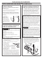
CONNECTING A GAS DRYER (skip for electric dryers)
•
Before beginning the installation, turn off
the circuit breaker(s) or remove the dryer’s circuit
fuse(s) at the electrical box. Be sure the dryer cord
is unplugged from the wall.
•
Turn the dryer’s gas shut-off valve in the supply
line to the OFF position.
•
Disconnect and discard old flexible gas connector
and ducting material.
Shut-off
Valve
5
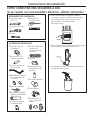
TOOLS YOU WILL NEED
MATERIALS YOU WILL NEED
10” Adjustable
wrenches (2)
8” Pipe wrench
Flat-blade
screwdriver
Level
Slip-joint pliers
4” dia. metal elbow
Pipe compound or
PTFE tape
Flexible gas line
connector
Duct clamps (2) or
Spring clamps (2)
Safety glasses
4” dia. metal duct
(recommended)
4” Cover Plate (Kit
WE49X22606)
4” dia., UL-listed
flexible metal duct
(if needed)
Gloves
Soap solution for
leak detection
Exhaust hood
Duct tape
Gas pipe adapters (2),
elbow and pipe plug

CONNECTING A GAS DRYER (cont.)
Installation Instructions
DRYER GAS SUPPLY CONNECTION
GAS SUPPLY
• A 1/8” National Pipe Taper thread plugged
tapping, accessible for test gauge connection,
must be installed immediately upstream of the
gas supply connection to the dryer. Contact
your local gas utility should you have questions
on the installation of the plugged tapping.
•
Supply line is to be 1/2” rigid pipe and equipped
with an accessible shutoff within 6 feet of, and
in the same room with, the dryer.
•
Use pipe thread compound appropriate for
natural or LP gas or use PTFE tape.
•
Connect flexible metal connector to dryer and
gas supply.
ADJUSTING FOR ELEVATION
• Gas clothes dryers input ratings are based on
sea level operation and need not be adjusted
for operation at or below 2000 ft. elevation. For
operation at elevations above 2000 ft., input
ratings should be reduced at a rate of 4 percent
for each 1000 ft. above sea level.
•
Installation must conform to local codes and
ordinances or, in their absence, the NATIONAL
FUEL GAS CODE, ANSI Z223.
• You must use with this dryer a flexible metal
connector (listed connector ANSI Z21.24/CSA 6.10).
The length of the connect shall not exceed 3 ft.
6
2"
2-5/8"
3/8" NPT MALE THREAD GAS SUPPLY
NOTE: Add to vertical dimension
the distance between cabinet
bottom to floor.
GAS REQUIREMENTS
- Explosion Hazard
WARNING
• Use a new CSA International approved flexible
gas supply line. Never reuse old flexible
connectors.
• Install an individual manual shut-off valve
within 6ft. of the dryer in accordance with the
National Fuel Gas Code, ANSI Z223.1/NFPA 54.
• Securely tighten all gas connections.
• If connected to LP gas, have a qualified person
make sure gas pressure DOES NOT exceed 13”
water column.
• Examples of a qualified person include: licensed
heating personnel, authorized gas company
personnel, and authorized service personnel.
• Failure to do so can result in death, explosion,
or fire.
• The installation must conform with local codes,
or in the absence of local codes, with the
National Fuel Gas Code, ANSI Z223.1/NFPA 54,
or the Natural Gas and Propane Installation
Code, CSA B149.1.
- Fire Hazard
WARNING
FOR USE WITH NATURAL GAS ONLY
Dryer as produced by manufacturer is to be used only
with a natural gas supply. A manufacturer-supplied
conversion kit is required to convert this dryer for
propane gas supply. Use propane gas conversion
kit WE25X217. Conversion must be made by properly
trained and qualified personnel in accordance with
local codes and ordinances.

Install a 1/8” NPT plugged tapping to the dryer
gas line shut-off valve for checking gas inlet
pressure.
Install a flare union adapter to the plugged
tapping.
NOTE: Apply pipe compound or PTFE tape
to the threads of the adapter and plugged
tapping.
Installation Instructions
Attach the flexible metal gas line connector to
the adapter.
B
Tighten the flexible gas line connection, using
two adjustable wrenches.
C
D
Tighten all connections, using two adjustable
wrenches. Do not overtighten.
E
CONNECTING THE DRYER TO THE GAS
SUPPLY (cont.)
Open the gas shut-off valve.
F
Apply pipe compound
or PTFE tape to all
male threads.
Shut-Off
Valve
Plugged
Tapping
CONNECTING THE DRYER TO THE GAS
SUPPLY
Install a female 3/8” NPT elbow at the end of the
dryer gas inlet.
Install a 3/8” flare union adapter to the female
elbow.
IMPORTANT: Use a pipe wrench to securely hold
on to the end of the dryer gas inlet to prevent
twisting the inlet.
NOTE: Apply pipe compound or PTFE tape to the
threads of the adapter and dryer gas inlet.
A
Apply pipe compound to the
adapter and dryer gas inlet.
7
Tighten the flexible
gas line using two
adjustable wrenches.
Elbow
Adapter
Items not supplied
Adapter
1/8” NPT
Pipe Plug for
Checking Gas
Inlet Pressure
Shut-Off Valve
Pipe size at
least 1/2”
3/8” NPT
New Metal
Flexible Gas
Line Connector

Installation Instructions
CONNECTING A GAS DRYER (cont.)
TEST FOR LEAKS
Never use an open flame to test for gas leaks.
Check all connections for leaks with soapy solution
or equivalent.
Apply a soap solution. The leak test solution must
not contain ammonia, which could cause damage
to the brass fittings.
If leaks are found, close the valve, retighten the
joint and repeat the soap test.
ELECTRICAL CONNECTION
INFORMATION FOR GAS DRYERS (cont.)
ELECTRICAL CONNECTION
INFORMATION FOR GAS DRYERS
- Electrical Shock Hazard
WARNING
Plug into a grounded 3 prong outlet.
DO NOT remove ground prong.
DO NOT use an adapter.
DO NOT use an extension cord.
Failure to do so can result in death, fire or electrical
shock.
• Circuit – Individual properly polarized and grounded
15 or 20 amp circuit breaker or time-delay fuse.
•
Power Supply – 2-wire plus ground, 120 Volt,
single phase, 60 Hz, alternating current.
•
Outlet Receptacle –
Properly grounded
3-prong receptacle to
be located so the power
cord is accessible when
the dryer is in an installed
position. If a 2-prong
receptacle is present, it
is the owner’s responsibility to have a licensed
electrician replace it with a properly grounded
3-prong grounding type receptacle.
Ensure proper
ground exists
before use.
GROUNDING INSTRUCTIONS
This dryer must be grounded. In the event of a
malfunction or breakdown, grounding will reduce
the risk of electric shock by providing a path of
least resistance for electric current. This dryer uses
a cord having an equipment-grounding conductor
and a grounding plug. The plug must be plugged
into an appropriate outlet that is properly installed
and grounded in accordance with all local codes
and ordinances.
WARNING
Improper connection of the
equipment-grounding conductor
can result in a risk of electric shock. Check with a
qualified electrician, or service representative or
personnel, if you are in doubt as to whether the
appliance is properly grounded. DO NOT modify the
plug on the power supply cord. If it will not fit the
outlet, have a proper outlet installed by a qualified
electrician.
SAVE THESE INSTRUCTIONS
• Dryer must be electrically grounded in
accordance with local codes and ordinances,
or in the absence of local codes, with the latest
edition of the NATIONAL ELECTRICAL CODE,
ANSI/NFPA NO. 70 or CANADIAN ELECTRICAL
CODE, CSA C22.1. Check with a licensed
electrician if you are not sure that the dryer is
properly grounded.
•
If required by local codes, an external 18 gauge
or larger copper ground wire (not provided)
may be added. Attach to dryer cabinet with a
#8-18 x ½” sheet metal screw (available at any
hardware store) to rear of dryer as illustrated.
Open Gas
Valve
Ground
Screw
8

Installation Instructions
CONNECTING AN ELECTRIC DRYER
(Skip for gas dryers and if your dryer already has a power cord attached)
Before making the electrical connection, turn off
the circuit breaker(s) or remove the dryer’s circuit
fuse(s) at the electrical box. Be sure the dryer cord
is unplugged from the wall.
NEVER LEAVE THE
ACCESS COVER OFF THE TERMINAL BLOCK.
9
MATERIALS YOU WILL NEED
4” dia. metal elbow
3/4” Strain relief
(UL recognized)
4” Duct clamps (2) or
4” spring clamps (2)
Safety glasses
4” dia. metal duct
(recommended)
4” Cover plate (Kit
WE49X22606)
Gloves
Exhaust hood
Duct tape
TOOLS YOU WILL NEED
Slip-joint pliers
Flat-blade
screwdriver
Phillips
screwdriver
Level
4” dia., UL-listed
flexible metal duct (if
needed)
Dryer power cord kit
(not provided with
dryer)
UL rated 120/240V,
30A with 3 or 4 prongs.
Identify the plug type
as per the house
receptacle before
purchasing line cord.

CONNECTING AN ELECTRIC DRYER (cont.)
Installation Instructions
ELECTRICAL CONNECTION
INFORMATION FOR ELECTRIC DRYERS
- Fire Hazard
WARNING
Use a new UL-listed 240V 30 amp dryer power supply
cord with closed ring terminals or spade terminals with
upturned ends.
Use a UL-listed strain relief.
Disconnect power before making electrical
connections.
Connect neutral wire (white or center wire) to center
terminal.
Ground wire (green or bare wire) must be connected to
green ground connector.
Connect remaining two supply wires to remaining two
terminals.
Securely tighten all electrical connections.
Replace the terminal block cover.
Failure to do so can result in death, fire or electrical
shock.
For electrical connections using a
power cord:
ELECTRICAL CONNECTION
INFORMATION FOR ELECTRIC DRYERS
For direct wire connections:
- Fire Hazard
WARNING
Use 10 gauge copper wire.
Use a UL-listed strain relief.
Disconnect power before making electrical
connections.
Connect neutral wire (white or center wire) to center
terminal.
Ground wire (green or bare wire) must be connected to
green ground connector.
Connect remaining two supply wires to remaining two
terminals.
Securely tighten all electrical connections.
Replace the terminal block cover.
Failure to do so can result in death, fire or electrical
shock.
GROUNDING INSTRUCTIONS
For a grounded, cord-connected dryer: This dryer
must be grounded. In the event of a malfunction
or breakdown, grounding will reduce the risk
of electric shock by providing a path of least
resistance for electric current. This dryer uses a
cord having an equipment-grounding conductor
and a grounding plug. The plug must be plugged
into an appropriate outlet that is properly installed
and grounded in accordance with all local codes
and ordinances.
WARNING
Improper connection of the
equipment-grounding conductor
can result in a risk of electric shock. Check with a
qualified electrician, or service representative or
personnel, if you are in doubt as to whether the
appliance is properly grounded. DO NOT modify the
plug on the power supply cord. If it will not fit the
outlet, have a proper outlet installed by a qualified
electrician.
SAVE THESE INSTRUCTIONS
GROUNDING INSTRUCTIONS
For a permanently connected dryer: This
dryer must be connected to a grounded metal,
permanent wiring system, or an equipment-
grounding conductor must be run with the circuit
conductors and connected to the equipment-
grounding terminal on the appliance.
WARNING
Improper connection of the
equipment-grounding conductor
can result in a risk of electric shock. Check with a
qualified electrician, or service representative or
personnel, if you are in doubt as to whether the
appliance is properly grounded.
SAVE THESE INSTRUCTIONS
10

Installation Instructions
CONNECTING DRYER USING 3-WIRE
CONNECTION
3-wire Connection
Not for use in Canada.
DO NOT use for Mobile Home Installations.
NOT for use on new construction.
NOT for use on recreational vehicles.
NOT for use in areas where local codes prohibit
grounding through the neutral conduction.
CONNECTING DRYER USING 4-WIRE
CONNECTION (MUST BE USED FOR
MOBILE HOME INSTALLATION)
NOTE: Since January 1, 1996, the National Electrical
Code requires that new constructions use a 4-wire
connection to an electric dryer. A 4-wire cord must
also be used where local codes do not permit
grounding through the neutral.
3-wire connection is NOT for use on new construction.
11
1. Turn off the circuit breaker(s) (30 amp) or remove
the dryer’s circuit fuse at the electrical box.
2. Be sure the dryer cord is unplugged from the wall
receptacle.
3. Remove the power cord cover located at the lower
back.
4. Remove and discard ground strap. Keep the green
ground screw for Step 7.
5. Install 3/4 in. UL-recognized strain relief to power
cord entry hole. Bring power cord through strain
relief.
6. Connect power cord as follows:
A. Connect the 2 hot lines to the outer screws of the
terminal block (marked L1 and L2).
B. Connect the neutral (white) line to the center of
the terminal block (marked N).
7. Attach ground wire of power cord with the green
ground screw (hole above strain relief bracket).
Tighten all terminal block screws (3) securely.
8. Properly secure power cord to strain relief.
9. Reinstall the cover.
NEVER LEAVE THE COVER OFF OF THE TERMINAL
BLOCK.
NEVER LEAVE THE COVER OFF OF THE TERMINAL
BLOCK.
If required, by local code, install external ground (not
provided) to grounded metal, cold water pipe, or
other established ground determined by a qualified
electrician.
L1
N
L2
RELOCATE GREEN
GROUND SCREW
HERE
STRAIN
RELIEF
BRACKET
GREEN OR
YELLOW WIRE
3/4", UL
RECOGNIZED
STRAIN RELIEF
HOT
WIRE
SCREWS
(3)
HOT
WIRE
COVER
NEUTRAL
(White)
REMOVE GROUND STRAP
AND DISCARD. KEEP GREEN
GROUND SCREW
4 #10 AWG MINIMUM COPPER
CONDUCTORS OR 120/240V 30A POWER
SUPPLY CORD KIT MARKED FOR USE
WITH DRYERS & PROVIDED WITH
CLOSED LOOP OR SPADE TERMINALS
WITH UPTURNED ENDS (NOT SUPPLIED).
L1
L2
STRAIN RELIEF
BRACKET
3/4", UL
RECOGNIZED
STRAIN RELIEF
HOT
WIRE
HOT
WIRE
GROUND
STRAP
GREEN
GROUND
SCREW
NEUTRAL
(White)
SCREWS
(3)
IF REQUIRED, BY LOCAL CODE,
INSTALL EXTERNAL GROUND
(NOT PROVIDED) TO GROUNDED
METAL, COLD WATER PIPE, OR
OTHER ESTABLISHED GROUND
DETERMINED BY A QUALIFIED
ELECTRICIAN.
COVER
3 #10 AWG MINIMUM COPPER
CONDUCTORS OR 120/240V 30A POWER
SUPPLY CORD KIT MARKED FOR USE
WITH DRYERS & PROVIDED WITH CLOSED
LOOP OR SPADE TERMINALS WITH
UPTURNED ENDS (NOT SUPPLIED).
1. Turn off the circuit breaker(s) (30 amp) or remove
the dryer’s circuit fuse at the electrical box.
2. Be sure the dryer cord is unplugged from the wall
receptacle.
3. Remove the power cord cover located at the lower
back.
4. Install 3/4-in. UL-recognized strain relief to power cord
entry hole. Bring power cord through strain relief.
5. Connect power cord as follows:
A. Connect the 2 hot lines to the outer screws of the
terminal block (marked L1 and L2).
B. Connect the neutral (white) line to the center of
the terminal block (marked N).
6. Be sure ground strap is connected to neutral
(center) terminal of block and to green ground
screw on cabinet rear. Tighten all terminal block
screws (3) securely.
7. Properly secure power cord to strain relief.
8. Reinstall the cover.

Installation Instructions
EXHAUSTING THE DRYER
12
CONNECTING THE DRYER TO HOUSE
VENT
RIGID METAL TRANSITION DUCT
•
For best drying performance, a rigid metal transition
duct is recommended.
•
Rigid metal transition ducts reduce the risk of crushing
and kinking.
UL-LISTED FLEXIBLE METAL CLOTHES DRYER
TRANSITION DUCT
•
If rigid metal cannot be used, then UL-LISTED flexible
metal clothes dryer transition duct (GE Appliances
parts –
PM08X10085) can be used.
•
Never install transition duct in walls, ceilings, floors or
other enclosed spaces.
• Total length of transition duct should not exceed
8’ (2.4 m).
• For many applications, installing elbows at both
the dryer and the wall is highly recommended (see
illustrations at right). Elbows allow the dryer to sit
close to the wall without kinking and/or crushing the
transition duct, maximizing drying performance.
•
Avoid resting the duct on sharp objects.
UL-LISTED FLEXIBLE METAL (FOIL-TYPE) TRANSITION
DUCT
•
In special installations, it may be necessary to connect the
dryer to the home exhaust vent using flexible metal (foil-type)
transition duct. UL–LISTED universal flexible dryer transition
duct (GE Appliances parts – PM8X73 or WX8X73) may be
used ONLY in
installations where rigid metal or flexible
metal transition ducting cannot be used AND where a 4”
diameter can be
maintained throughout the entire length of
the transition duct
.
•
In Canada and the United States, only transition ducts
that comply with “UL 2158A STANDARD FOR CLOTHES
DRYER TRANSITION DUCT” shall be used.
•
Avoid resting the duct on sharp objects.
•
For best drying performance:
1. Slide one end of the duct over the clothes dryer
outlet pipe.
2. Secure the duct with a clamp.
3. With the dryer in its permanent position, extend
the duct to its full length. Allow 2
”
of duct to
overlap the exhaust pipe. Cut off and remove
excess duct. Keep the duct as straight as
possible for maximum airflow.
4. Secure the duct to the exhaust pipe with the
other clamp.
- Fire Hazard
WARNING
This dryer MUST be vented to the outdoors.
Use only 4” rigid metal ducting for the home
exhaust vent.
Use only 4” rigid metal or UL-LISTED transition duct
to connect the dryer to the home exhaust duct.
DO NOT use a plastic vent.
DO NOT exhaust into a chimney, kitchen exhaust,
gas vent, wall, ceiling, attic, crawl space, or
concealed space of a building.
DO NOT install a screen in or over the exhaust duct.
DO NOT install a booster fan in the exhaust duct.
DO NOT use duct longer than specified in the
exhaust length table.
Failure to follow these instructions can result in
death or fire.
TOOLS AND MATERIALS YOU WILL
NEED TO INSTALL EXHAUST DUCT
Phillips-head
screwdriver
Duct tape or
duct clamp
Rigid or UL-listed
flexible metal 4”
(10.2 cm) duct
Drill with 1/8” drill bit
(for bottom venting)
Hacksaw
Vent hood
PARTS AVAILABLE FROM GEAPPLIANCES.COM
OR LOCAL SERVICE ORGANIZATIONS
PM8X85
Outdoor exhaust hood
PM08X10085
8’ Flexible metal clothes dryer
transition duct with 2 clamps
WX08X10130
4” Dryer exhaust clamp
WE49X22606
Rear exhaust opening cover, for side
or bottom vented dryers

Installation Instructions
Using exhaust longer than specified length will:
• Increase the drying times and the energy cost.
• Reduce the dryer life.
• Accumulate lint, creating a potential fire
hazard.
The correct exhaust installation is YOUR
RESPONSIBILITY.
Problems due to incorrect installation are not
covered by the warranty.
The MAXIMUM ALLOWABLE length of the exhaust
system depends upon the type of duct, number of
turns, the type of exhaust hood (wall cap) and all
conditions noted on the chart.
• Internal elbows added for side or bottom vent
conversions must be included in the total elbow
count.
• Any elbow greater than 45° should be treated as
a 90° elbow.
• Two 45° elbows will be treated like one 90°
elbow.
• For every additional 90° elbow, reduce the
allowable vent system length by 10 feet.
• When calculating the total vent system length,
you must add all the straight portions and elbows
of the system (including the transition duct).
EXHAUST LENGTH
13
• DO NOT bend
or collapse
ducting. Use
elbows if turns
are necessary.
• DO NOT use
excessive
exhaust
length. Cut
duct as short
as possible.
• DO NOT
crush duct
against the
wall
.
• DO NOT
set dryer
on duct
.
• DO cut duct as short
as possible and install
straight into wall.
•
DO use elbows when
turns are necessary.
Elbows
4" DIA.
4"
4" DIA.
4" DIA.
2-1/2"
RECOMMENDED MAXIMUM LENGTH
Exhaust Hood Types
Recommended
No. of 90°
Elbows
Rigid
Metal
Rigid
Metal
90 Feet
60 Feet
45 Feet
35 Feet
25 Feet
60 Feet
45 Feet
35 Feet
25 Feet
15 Feet
0
1
2
3
4
Use only for short
run installations
EXHAUST LENGTH

EXHAUSTING THE DRYER (cont.)
Installation Instructions
BEFORE YOU BEGIN
• Remove and discard existing plastic or metal foil
duct and replace with UL-listed duct.
•
Remove any lint from the wall exhaust opening.
Internal
Duct
Opening
Wall
Check that exhaust
hood damper opens
and closes freely.
STANDARD REAR EXHAUST
We recommend that you install your dryer before
installing your washer. This will permit direct
access for easier exhaust connection.
Slide the end of the exhaust duct on the back of the
dryer and secure with duct tape or a hose clamp.
NOTE: We strongly recommend using rigid metal
exhaust duct.
•
For straight-line installation, connect the dryer
exhaust to the wall, using duct tape.
RECOMMENDED CONFIGURATION TO
MINIMIZE EXHAUST BLOCKAGE
Using duct elbows will prevent duct kinking and
collapsing.
Duct
Transition
Ducting
Wall Side
Dryer
Side
14
EXHAUST SYSTEM CHECKLIST
HOOD OR WALL CAP
•
Terminate in a manner to prevent back drafts or entry
of birds or other wildlife.
•
Termination should present minimal resistance to
the exhaust airflow and should require little or no
maintenance to prevent clogging.
•
Wall caps must be installed at least 12” above ground
level or any other obstruction with the opening
pointed down.
SEPARATION OF TURNS
•
For best performance, separate all turns by at least
4 ft. of straight duct, including distance between last
turn and dampened wall cap.
SEALING OF JOINTS
•
All joints should be tight to avoid leaks. The male end
of each section of duct must point away from the
dryer.
•
Duct joints should be made air- and moisture-tight
by wrapping the overlapped joints with duct tape or
aluminum tape.
•
Do not assemble ductwork with any fasteners
that extend into the duct. These fasteners can
accumulate lint, creating a potential fire hazard.
• Horizontal runs should slope down towards the
outdoors 1/4” per foot.
•
Provide an access for inspection and cleaning of
the exhaust system, especially at turns and joints.
Exhaust system shall be inspected and cleaned at
least once a year.
INSULATION
•
Ductwork that runs through an unheated area or is
near air conditioning should be insulated to reduce
condensation and lint buildup.

15
Installation Instructions
SIDE OR BOTTOM VENTING
Dryer Exhaust to right of cabinet for Electric
models only.
Dryer Exhaust to left of cabinet for Gas and
Electric models.
Dryer Exhaust to the bottom of cabinet for
Gas and Electric models.
Detach and remove the right (electric models only),
left or bottom knockout as desired. Remove the
screw inside the dryer exhaust duct and save. Pull
the duct out of the dryer.
Cut the duct as shown and keep portion A.
ADDING A NEW DUCT
Reconnect the cut portion (A) of the duct to the
blower housing. Make sure that the shortened
duct is aligned with the tab in the base. Use the
screw saved previously to secure the duct in place
through the tab on the appliance base.
ADDING ELBOW AND DUCT FOR EXHAUST TO
LEFT OR RIGHT SIDE OF CABINET
• Preassemble 4” elbow with 4” duct. Wrap duct
tape around joint.
•
Insert duct assembly, elbow first, through the
side opening and connect the elbow to the dryer
internal duct.
Be sure not to pull or damage the electrical wires
inside the dryer when inserting the duct.
Fixing hole
A
13
1
ø2” (34.29cm)
TAB LOCATION
- Fire Hazard
WARNING
Close the back opening with cover plate (Kit
WE49X22606).
Disconnect dryer from electrical supply.
Wear gloves and arm guards.
Failure to do so may result in fire, electrical shock
or lacerations.
Remove
screw
and save
Remove desired
knockout (one only)
Right
(electric
models
only)
Left
Bottom
Through the rear opening, locate the tab in the
middle of the appliance base. Lift the tab to about
45°,
using a flat-blade screwdriver.
Bend tab
up 45°
Not for gas
Portion “A”
Right (electric
models only)
or left side
exhaust
Fixing hole
Left
Right
Exhaust can be
added to left or
right (electric
models only) side
Duct
tape
Right
Left

EXHAUSTING THE DRYER (cont.)
Installation Instructions
SIDE OR BOTTOM VENTING (cont.)
ADDING COVER PLATE TO REAR OF CABINET
ADDING ELBOW AND DUCT FOR EXHAUST TO
LEFT OR RIGHT SIDE OF CABINET (cont.)
• Apply duct tape as
shown on the joint
between the dryer
internal duct and the
elbow, and also the joint
between the elbow and
the side duct.
Use 4” rigid metal ducting only inside the dryer.
Internal duct joints must be secured with tape,
otherwise they may separate and cause a safety
hazard.
16
DUCT
TAPE
ADDING ELBOW FOR EXHAUST THROUGH
BOTTOM OF CABINET
• Insert the elbow through the rear opening and
connect it to the dryer internal duct.
•
Apply duct tape as
shown on the joint
between the dryer
internal duct and the
elbow, and also the
joint between the
elbow and the bottom
duct.
Internal duct joints must be secured with tape;
otherwise, they may separate and cause a safety
hazard.
Duct tape
FINAL SETUP
LEVEL THE DRYER
Stand the dryer upright near the final location and
adjust the four leveling legs at the corners to ensure
that the dryer is level from side to side and front to
rear.
Lower
Raise
PLUG DRYER IN
1
2
DRYER START-UP
Press the Power button.
NOTE: If the dryer has been exposed to
temperatures below freezing for an extended
period of time, allow it to warm up before pressing
Power. Otherwise, the display will not come on.
The dryer is now ready for use.
3
Ensure proper
ground exists
before use.
Connect standard metal elbows and ducts to
complete the exhaust system. Cover back opening
with the plate (kit WE49X22606) which can be
purchased from GEApplianceparts.com or a local
service provider. Place dryer in final location.
Plate
(Kit WE49X22606)
NEVER LEAVE THE BACK OPENING WITHOUT THE
PLATE.

Lea estas instrucciones por completo y con
detenimiento.
•
IMPORTANTE – Guarde estas instrucciones
para el uso de inspectores eléctricos locales.
•
IMPORTANTE – Cumpla con todos los
códigos y ordenanzas vigentes.
•
Instale la secadora de acuerdo con las instrucciones
del fabricante y los códigos locales.
• Nota al instalador – Asegúrese de dejar estas
instrucciones con el consumidor.
• Nota al usuario – Conserve estas instrucciones para
referencia futura.
•
La instalación de la secadora debe efectuarla un
instalador calificado.
•
Esta secadora debe tener una salida al exterior.
•
Antes de que la secadora antigua sea retirada del
servicio o eliminada, quítele la puerta.
•
La información sobre reparaciones y el diagrama del
cableado se encuentran en la consola de control.
•
No permita que niños se suban o se metan dentro
del artefacto. Se requiere una supervisión estricta
cuando el aparato es utilizado cerca de niños.
•
El instalador tiene la responsabilidad de efectuar una
instalación adecuada.
•
La garantía no cubre las fallas del producto debido a
una instalación incorrecta. .
• Instale la secadora en lugares donde la temperatura
sea mayor a 50°F para un funcionamiento
satisfactorio del sistema de control de la secadora.
• Quite y descarte el conducto existente de plástico
o de papel de aluminio y coloque un conducto
aprobado por UL.
Instrucciones Secadora
de instalación
04
Si tiene alguna pregunta, llame GE Appliances a 800.GE.CARES (800.432.2737) o visite nuestro sitio Web en: GEAppliances.com
ADVERTENCIA
- Riesgo de incendio
•
La instalación de la secadora debe efectuarla
un instalador calificado.
•
Instale la secadora de ropa de acuerdo con estas
instrucciones y en cumplimiento con los códigos
locales
•
NO instale una secadora de ropa con conductos
de plástico flexible. Si se instala un conducto
flexible de metal (semi rígido o de tipo papel de
aluminio), debe estar aprobado por UL e instalarse
de acuerdo con las instrucciones de “Cómo
conectar la secadora a la ventilación doméstica”
de este manual. Los materiales de los conductos
flexibles a menudo se desploman, se aplastan y
atrapan pelusas. Estas condiciones obstruyen la
corriente de aire de la secadora e incrementan el
riesgo de incendio.
•
NO instale o almacene este aparato en un
lugar donde se vea expuesto al agua o a las
inclemencias del tiempo.
•
Para reducir el riesgo de una lesión grave o de
muerte, cumpla con todas las instrucciones de
instalación.
• Guarde estas instrucciones. (Instaladores: Asegúrense
de dejar estas instrucciones al consumidor).
ANTES DE COMENZAR
31-16769-3 08-16 GEA
234D2274P004
EN LA MANCOMUNIDAD DE
MASSACHUSETTS, SE APLICAN LAS
INSTRUCCIONES DE INSTALACIÓN
SIGUIENTES:
• Este producto debe instalarlo un plomero
matriculado o un instalador de gas.
•
Cuando use válvulas esféricas de apagado de
gas, deberán ser del tipo de manija en T.
•
Si se usa una conexión flexible para gas, ésta
no debe superar 1 m (3 pies).
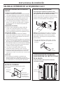
SECADORAS A GAS ÚNICAMENTE

4,4”
(11,2 cm)
Instrucciones de instalación
Incline la secadora de costado y saque los soportes de espuma de
embalaje tirando de los costados y quitándolos de las patas de la secadora.
Asegúrese de quitar todas las piezas de espuma de las patas.
Saque la bolsa que contiene la información.
CÓMO DESEMPACAR LA SECADORA
Visión lateral
5.4”
(13,7 cm)
DIMENSIONES
APROXIMADAS
Visión frontal
NOTE :
La altura de la secadora puede ser ajustada para quedar a la misma a altura
de la lavadora
Con pedestal: 52.1” (132.33 cm)
Apilada: 84” (213.36 cm)
33” (83,8 cm)
39.3”
(99,8cm)
27”
(68,6 cm)
39,3”
(99,8 cm)
CABLES DE CORRIENTE:
GE Appliances recomienda enfáticamente el uso de piezas
específicas de fábrica. Seleccione el cable de corriente que se
adecúe a sus requisitos de instalación.
GE Appliances recomienda enfáticamente el uso de
piezas específicas de fábrica. A continuación figura una
lista de mangueras de fábrica que podrá adquirir. Dichas
mangueras son fabricadas y probadas de modo que se
cubran las especificaciones de GE Appliances.
GE Appliances recomienda enfáticamente el uso de nuevas
mangueras de suministro de agua. Con el paso del tiempo, las
mangueras se degradan y deben ser reemplazadas cada 5 años, a fin
de reducir el riesgo de fallas sobre las mismas y daños con el agua.
Piezas y Accesorios
Ordene hoy a través de Internet en GEAppliancesparts.com,
las 24 horas del día o en forma telefónica llamando al
800.626.2002, durante el horario comercial habitual.
MANGUERA DE VAPOR Y AGUA (sólo para los modelos de secadoras de vapor):
Pieza Nº Tipo Longitud Amperios
WX9X2 3-Clavijas 4 Pies 30
WX9X3 3-Clavijas 5 Pies 30
WX9X4 3-Clavijas 6 Pies 30
WX9X18 4-Clavijas 4 Pies 30
WX9X19 4-Clavijas 5 Pies 30
WX9X20 4-Clavijas 6 Pies 30
ACCESORIOS:
Ordene hoy a través de Internet en GEAppliancesparts.com,
las 24 horas del día o en forma telefónica llamando al
800.626.2002, durante el horario comercial habitual.
Pieza Nº
Accesorio
SBSD137HWW
Pedestal blanco 27” de ancho
SBSC137HDG
Pedestal gris diamante 27” de ancho
GEFLSTACK Kit para apilar Secadora sobre Lavadora
PM08X10085
Ducto de transición de metal flexible
WE01X20677
Estante de secadora para zapatos
Número de Pieza Accesorio
WE25X20060 Kit Completo (mangueras, adaptador
en Y, arandelas) o
WE49X25794 Kit (Manguera corta, adaptador en Y,
arandelas) y
WE1M847
Manguera Larga
O POR SEPARADO
WE1M847
Manguera Larga y
WE1M848
Manguera Corta
2

3
Instrucciones de instalación
INSTALACIÓN EN CASAS MÓVILES
O PREFABRICADAS
• Instalación debe cumplir con la NORMA
SOBRE CONSTRUCCIÓN Y SEGURIDAD DE CASAS
PREFABRICADAS, TÍTULO 24, PARTE 32-80 o
Norma CAN/CSA-Z240 MH, o, cuando dicha
norma no sea aplicable, con la NORMA NACIONAL
ESTADOUNIDENSE PARA CASAS MÓVILES, ANSI/
NFPA Nº 501B.
•
La secadora DEBE tener ventilación al exterior.
•
La ventilación del escape DEBERÁ estar ajustado
de forma segura a una parte no combustible de
la casa rodante.
•
La ventilación NO DEBE terminar debajo de una
casa móvil o prefabricada.
•
El material del conducto de ventilación DEBE SER
METAL.
•
DEBE utilizarse el KIT 14-D346-33 para conectar
bien la secadora a la estructura.
•
La ventilación NO DEBE conectarse a ningún otro
conducto, ventilación o chimenea.
•
NO utilice tornillos para placas de metal u otros
dispositivos de sujeción que se extiendan
al interior de la ventilación de salida.
•
Debe contar con una abertura con un espacio
libre de por lo menos 25 pulgadas cuadradas
para el ingreso de aire exterior dentro de la
secadora habitación.
•
Para acceder a información sobre la conexión
eléctrica, consulte la section.
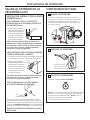
REQUERIMIENTOS PARA INSTALACIÓN
EN NICHOS O ARMARIOS
- Riesgo de
explosión
ADVERTENCIA
Mantenga cualquier material y vapores inflamables,
tales como gasolina, alejados de la secadora.
Coloque la secadora a por lo menos 18” (46 cm.) del
piso cuando sea instalada en un garaje.
Si no se cumple con esto, se podrá producir una
explosión, incendio o la muerte.
• Esta secadora DEBE tener una ventilación
al exterior. Ver la sección SALIDA AL EXTERIOR
DE LA SECADORA.
•
El espacio libre mínimo entre la secadora y las
paredes adyacentes u otras superficies es:
0” en ambos lados
1” en el frente
1” en la parte trasera
1” en la parte superior
•
Se deberá considerar que se debe brindar el
despeje adecuado para la instalación y el servicio
técnico.
•
Las puertas del armario deben contar con rejillas
u otro tipo de ventilación y tener por lo menos
60 pulgadas cuadradas de espacio abierto. Si el
armario incluye una lavadora y una secadora,
las puertas deben
contener un mínimo de 120
pulgadas cuadradas
de espacio abierto.
NOTA: CUANDO EL CONDUCTO DE ESCAPE SE
ENCUENTRA EN LA PARTE TRASERA DE LA SECADORA,
LA CONFIGURACIÓN DEL DUCTO DE ESCAPE PUEDE
REQUERIR MAS DE 1” DE ESPACIO EN LA PARTE
TRASERA.
Secadoras a Gas Únicamente:
• No se deberá instalar ningún otro electrodoméstico
que consuma combustible en el mismo armario
donde haya una secadora a gas.
• La secadora se deberá desconectar de la tubería de
suministro de gas durante la prueba de presión en
presiones superiores a ½ psi (3.5 kPa).
• Una rosca cubierta NPT de 1/8”, accesible para
la conexión de un dispositivo de calibración,
deberá ser instalada inmediatamente arriba de la
conexión del suministro de gas a la secadora.
ESPACIO LIBRE MÍNIMO EN OTROS
ESPACIOS QUE NO SEAN INSTALACIONES
EN NICHOS O ARMARIOS
Los espacios libres mínimos respecto de superficies
combustibles y de aberturas de aire son: 0” a ambos
lados; 1” (7,62 cm) en la parte trasera; 1” (2,54 cm)
en la parte superior. Debe tenerse en cuenta un
espacio libre adecuado para un funcionamiento y
reparación correctos.

4
Instrucciones de instalación
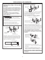
CÓMO CONECTAR MANGUERAS DE ENTRADA
(sólo para los modelos de secadoras de vapor)
CÓMO CONECTAR MANGUERAS
DE ENTRADA
Para producir vapor, la secadora debe conectarse
al suministro de agua fría. Ya que la lavadora
también debe conectarse al agua fría, debe
introducirse un conector en “Y” para permitir
que ambas mangueras de entrada puedan
utilizarse al mismo tiempo.
NOTA: Utilice nuevas mangueras de entrada; nunca
utilice mangueras viejas.
1. Cierre el grifo de agua fría. Quite la manguera
de entrada de la lavadora del conector de la
válvula de llenado (fría).
2. Asegúrese de que la arandela plana de goma se
encuentre en su lugar y sujete una unión hembra
de la manguera corta provistas en el conector
de la válvula de llenado de la lavadora. Ajuste a
mano hasta que esté firmemente asentada.
3. Sujete un extremo macho del conector en “Y” a la
unión hembra de la manguera corta. Asegúrese
de que la arandela plana de goma se encuentre
en su lugar. Ajuste a mano hasta que esté
firmemente asentada.
4. Introduzca el filtro en la unión de la manguera
de entrada de la lavadora. Si la arandela plana
de goma ya se encuentra en su lugar, quítela
antes de instalar el filtro. Sujete esta unión
a un extremo macho del conector en “Y”. Ajuste
a mano hasta que esté firmemente asentada.
5. Asegúrese de que la arandela de goma plana se
encuentra en su posición y coloque una manguera
de entrada de agua de 4 a 6 pies de largo (puede
ser necesario comprarla por separado) a un
extremo macho del conector ‘’Y‘’. Apriete con la
mano hasta que quede firmemente asentado.
6. Asegúrese de que la arandela plana de goma
se encuentre en su lugar y sujete el otro extremo
de la manguera larga de entrada al conector
de la válvula de llenado en la parte inferior del
panel trasero de la secadora. Ajuste a mano
hasta que esté firmemente asentada.
CÓMO CONECTAR MANGUERAS
DE ENTRADA (cont.)
7. Utilizando alicates, ajuste todas las uniones con
un giro adicional de dos tercios.
NOTA: No ajuste de más. Pueden dañarse las
uniones.
8. Abra el grifo de agua.
9. Controle la presencia de pérdidas alrededor
del conector en “Y”, el grifo y las uniones
de las mangueras.
REQUISITOS DE SUMINISTRO DE AGUA
Los grifos de agua caliente y fría DEBEN instalarse
dentro de las 42 pulg. (107 cm) de la entrada de
agua de la lavadora. Los grifos DEBEN ser del tipo
de manguera de jardín de 3/4 pulg. (1.9 cm) para
que las mangueras de entrada puedan conectarse.
La presión de agua DEBE hallarse entre 10 y 120
libras por pulgada cuadrada. La compañía de agua
puede informarle sobre la presión de agua.
NOTA: Se recomienda el uso de un suavizante de
agua para reducir la acumulación de sarro dentro
del generador de vapor si el suministro doméstico
contiene agua muy dura.
Page is loading ...
Page is loading ...
Page is loading ...
Page is loading ...
Page is loading ...
Page is loading ...
Page is loading ...
Page is loading ...
Page is loading ...
Page is loading ...
Page is loading ...
Page is loading ...
-
 1
1
-
 2
2
-
 3
3
-
 4
4
-
 5
5
-
 6
6
-
 7
7
-
 8
8
-
 9
9
-
 10
10
-
 11
11
-
 12
12
-
 13
13
-
 14
14
-
 15
15
-
 16
16
-
 17
17
-
 18
18
-
 19
19
-
 20
20
-
 21
21
-
 22
22
-
 23
23
-
 24
24
-
 25
25
-
 26
26
-
 27
27
-
 28
28
-
 29
29
-
 30
30
-
 31
31
-
 32
32


Ask a question and I''ll find the answer in the document
Finding information in a document is now easier with AI
in other languages
- español: GE GFD45ESPKDG Guía de instalación
Related papers
-
GE GFD45GSSMWW Installation guide
-
GE GFDS175GHDG Installation guide
-
GE GFD55ESSN0WW Owner's manual
-
-
GE GTX22GASKWW Installation guide
-
GE 1105614 Installation guide
-
GE GTX42EASJWW Installation guide
-
GE Appliances GTX33EASKWW User manual
-
GE GTX22GASKWW Installation guide
-
Other documents
-
-
LG Electronics DLEX5000W Installation guide
-
-
LG Electronics DLGX3901B Installation guide
-
-
-
-
-
Whirlpool WED9500EC0 Installation guide
-
Maytag MEDB955FC Installation guide