Page is loading ...

For questions or help with this product contact Tech Support at (570) 546-9663 or techsupport@grizzly.com
MODEL T31563
BUILD-YOUR-OWN
MOBILE BASE KIT
INSTRUCTIONS
COPYRIGHT © SEPTEMBER, 2019 BY GRIZZLY INDUSTRIAL, INC.
NO PORTION OF THIS MANUAL MAY BE REPRODUCED IN ANY SHAPE
OR FORM WITHOUT THE WRITTEN APPROVAL OF GRIZZLY INDUSTRIAL, INC.
(FOR MODELS MFD. SINCE 07/19) #AI20549 PRINTED IN CHINA
Introduction
The Model T31563 Bear Crawl Build-Your-Own
Mobile Base Kit allows you to build a custom size
base to fit a wide variety of machines.
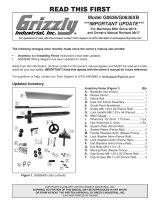
Description Qty
A. Right Front Corner Bracket ........................ 1
B. Left Front Corner Bracket ........................... 1
C. Right Rear Corner Bracket ......................... 1
D. Left Rear Corner Bracket ........................... 1
E. Top Plates ................................................... 4
F. 3" Swivel Casters (Front) ............................ 2
G. 3" Wheel (Rear) .......................................... 2
H. Foot Pedals ................................................ 2
I. Feet ............................................................ 2
—Foot Pedal Plunger ............................1 Ea
—Compression Spring ..........................1 Ea
—Rubber Foot .......................................1 Ea
—Hex Nut M10-1.5 ................................1 Ea
J. Bearing Sleeves ......................................... 4
K. Shoulder Bolts M8-1.25 x 50 (Pedals) ........ 2
L. Shoulder Bolts M10-1.5 x 55 (Casters) ....... 2
M. Hardware (Not Shown)
—Flat Hd Screws M8-1.25 x 30 (
1
⁄2" Base)
................................................................. 12
—Flat Hd Screws M8-1.25 x 40 (
3
⁄4" Base)
................................................................. 12
—Hex Bolts M8-1.25 x 16 (Casters) ........... 8
—Flange Nuts M8-1.25 (Base) ................. 12
—Lock Nuts M8-1.25 (Casters, Pedals) ... 10
Inventory
V1.09.19
Specifications
• Minimum Inside Dimensions .......... 12" x 12"
• Minimum Base Thickness ........................
1
⁄2"
• Maximum Weight Capacity (
1
⁄2") ...... 400 lbs.
• Maximum Weight Capacity (
3
⁄4"+) .... 600 lbs.
Materials Needed for Assembly
• Plywood (See Page 2) ............................... 1
• Table Saw or Circular Saw ......................... 1
• Measuring Tape .......................................... 1
• Pencil .......................................................... 1
• Drill Press or Handheld Drill ....................... 1
• Drill Bit
3
⁄8" .................................................. 1
• Phillips Screwdriver #2 ............................... 1
• Wrench or Socket 12, 13, and 14 mm ........ 1
• Open-End Wrench 17mm ........................... 1
• Machine-Specific Hardware
(See Page 5) ........................................1 Set
Figure 1. Inventory.
A B
F
I
J
K L
DC
H
E
G

-2-
T31563 Mobile Base Kit (Mfd. Since 07/19)
Base Plate Material
The best material for the base plate is a natural
wood plywood (hardwood plywood is best). Avoid
using OSB, MDF, or particle board, as these
materials are generally not strong enough to hold
heavy machinery for a long period of time.
3
⁄4" plywood is recommended to make the base
plate, with the included 40mm flat head screws.
However, 30mm flat head screws are also includ-
ed for use with
1
⁄2" plywood. For base plates over
3
⁄4", longer flat head screws must be acquired
separately. Use good judgement to determine the
material that best fits your needs.
Preparing Base Plate for Assembly
The size requirements of the base plate vary
depending on the size and weight of the machine
you plan to put on the mobile base. The purpose
of this section is to help you decide the size of
base plate that works best for your machine.
Figure 2. Example of wider base plate.
Machine
Base
Base
Plate
2X (min.)
X
To prepare base plate:
1. Measure footprint of machine base.
2. Cut base plate to chosen measurements.
— If you plan on making the base plate
the same dimensions as the machine
base, add 1" to the width and the depth.
This extra space will make mounting eas-
ier and will hardly be noticeable once the
machine is mounted.
— If you plan on making the base plate larger
than the machine base to increase stabil-
ity, don't make the base plate so large it
becomes a tripping hazard.
3. Use a corner bracket as a template and mark
mounting hole locations on each corner of the
base plate.
4. Drill
3
⁄8" mounting holes at marked locations.
Note: Think about the final appearance of
your mobile base. If you are concerned about
how the exposed portions of the base plate
will look in your shop, paint or finish the base
plate before completing the assembly.
Operating machinery on an unsecured
mobile base may allow the machine to
shift unexpectedly, which could result in
accidental contact with the cutting device
or other moving parts.
If the machine is top-heavy or has a narrow base,
there is an increased risk of tipping when moving
it around on a mobile base. To reduce this risk,
make your base plate wider than the machine
base (see Figure 2). Always secure the machine
to the base plate for added stability—this will
reduce the risk of tipping the machine over when
moving it around the shop. See instructions for
mounting the machine on Page 5.

T31563 Mobile Base Kit (Mfd. Since 07/19)
-3-
3. Attach foot pedal to each front corner bracket
with M8-1.25 x 50 shoulder bolt and M8-1.25
lock nut (see Figure 5).
1. Attach swivel caster to each front corner
bracket with (4) M8-1.25 x 16 hex bolts and
(4) M8-1.25 lock nuts (see Figure 3).
Assembling Mobile Base
4. Attach wheel to each rear corner bracket with
M10-1.5 x 55 shoulder bolt and (2) bearing
sleeves (see Figure 6).
Figure 6. Wheel attached to rear corner bracket.
Fixed Caster Wheel
Figure 5. Attaching foot pedals.
Foot
Pedal
2. Install foot pedal plunger and spring into each
front corner bracket and attach adjustable
foot with M10-1.5 hex nut to the bottom of
each foot pedal plunger (see Figure 4).
Figure 3. Swivel caster attached to front corner
bracket.
Figure 4. Installing foot pedal plunger and
spring.
Foot Pedal
Plunger
Spring
Adjustable
Foot
Front Corner
Bracket
Swivel
Caster

-4-
T31563 Mobile Base Kit (Mfd. Since 07/19)
5. Slide top plate tabs into left front corner
bracket (see Figure 7). Attach bracket and
top plate to base plate with (3) M8-1.25 flat
head screws and (3) M8-1.25 flange nuts.
Note: 40mm flat head screws are used with
3
⁄4" base plate and 30mm flat head screws are
used with
1
⁄2" base plate.
Adjusting Rubber Feet
The height of the rubber feet can be adjusted
to stabilize the machine. To ensure the machine
does not move during operations, always make
sure the adjustable rubber feet (see Figure 9) are
firmly touching the ground before operating the
machine.
Tools Needed Qty
Open-End Wrench 17mm .................................. 1
To adjust rubber foot height:
1. Loosen hex nut on each foot to allow foot
(see Figure 9) to move up or down as need-
ed.
Typical Direction of Movement
(TOP VIEW OF CASTER)
CORRECT INCORRECT
Figure 8. Correct orientation of fixed casters.
Figure 7. Corner bracket and top plate installed.
6. Repeat Step 5 for each corner bracket.
Note: Ensure fixed casters are oriented in
direction machine will typically be moved
(see Figure 8). Mounting fixed casters in
wrong direction will make it difficult to move
mobile base around in small spaces.
2. With all casters on the ground, lower each
foot to firmly touch the ground without lifting
caster.
3. Tighten hex nut on each foot.
Figure 9. Rubber foot and hex nut adjustment.
Rubber Foot
Hex
Nut
Top Plate

T31563 Mobile Base Kit (Mfd. Since 07/19)
-5-
Mounting Machine to Mobile Base
1. Lower rubber feet to ensure mobile base
is secure (see Adjusting Rubber Feet on
Page 4).
2. With the help of an assistant, place machine
on base plate.
Figure 10. Foot pedal raised.
Foot Pedal
Lifting heavy machinery
or parts without proper
assistance or equipment
may result in strains, back
injuries, crushing injuries,
or property damage.
To avoid serious personal injury, keep
hands and fingers clear of machine base
and mobile base pinch points when placing
machine.
4. Raise foot pedals up to lift rubber feet and
move machine (see Figure 10).
3. Position machine near front or center of base
plate, so mobile base will not be a tripping
hazard.
4. Drill mounting holes of appropriate size using
machine stand as template.
5. Secure machine with through bolts, flat wash-
ers, lock washers, and hex nuts (see Figure
11).
Figure 11. Example of drill press mounted to
base plate.
IMPORTANT: When moving the mobile base, the
rubber feet should not touch the floor. Likewise,
when operating the machine, ensure that the rub-
ber feet are fixed firmly against the floor to provide
stability, without lifting casters.

-6-
T31563 Mobile Base Kit (Mfd. Since 07/19)
Using Mobile Base
1. DISCONNECT MACHINE FROM POWER!
2. With machine mounted on mobile base,
adjust each rubber foot so it clears floor by at
least
1
⁄8". Refer to Adjusting Rubber Feet on
Page 4 for details.
— If floor is uneven, retract feet completely to
eliminate the chance of the pads dragging.
3. Check to make sure machine pathway is
clear of all obstructions.
4. Push machine from lowest possible point to
avoid tipping it over, and move it to its new
location. The best control is usually achieved
by pushing from swivel caster side of base.
— If the machine is large, get an assistant to
help stabilize the machine while it is being
moved.
5. Adjust each foot until it touches floor, then
lower each foot at least an additional half-
turn. This ensures major load of machine is
on feet rather than on casters.
6. Check machine to make sure it is stable in
its new location, and make sure machine is
clear of any obstructions before reconnecting
power and turning machine ON.
To reduce risk of serious injury when using
this mobile base:
1. LOCKING FEET. Do not operate machine
on mobile base unless both mobile base feet
firmly contact floor and raise base enough
to disable casters. Using the machine on
base when it is not secured could result in
a loss of workpiece control.
2. MACHINE STABILITY. Test for stability
after placing the machine in its new location.
Adjust feet so they each they touch the
ground, then push on machine at several
locations, making sure it is not off balance.
The hex nuts can be adjusted up to top of
foot assembly to lock foot height setting.
Before moving machine and mobile base,
check to make sure pathway is clear of
any hoses, wires, tools or shop debris. An
abrupt impact with an object along path of
travel can lock a wheel and cause machine
to fall over, resulting in serious personal
injury. Disconnect machine from power
supply or dust collection before moving.

T31563 Mobile Base Kit (Mfd. Since 07/19)
-7-
BUY PARTS ONLINE AT GRIZZLY.COM!
Scan QR code to visit our Parts Store.
1
2
3
4
5,6
5,6
7
7
8
8
9
9
10
11
12
13
14
15
16
17
18
19
19
20
T31563 Parts Breakdown & List
REF PART # DESCRIPTION REF PART # DESCRIPTION
1 PT31563001 LEFT FRONT CORNER BRACKET 11 PT31563011 HEX BOLT M8-1.25 X 16
2 PT31563002 RI GHT FRONT CORNER BRACKET 12 PT31563012 CASTER, 3" SWIVEL
3 PT31563003 LEFT REAR CORNER BRACKET 13 PT31563013 SHOULDER BOLT M8-1.25 X 8, 8 X 50
4 PT31563004 RI GHT REAR CORNER BRACKET 14 PT31563014 FOOT PEDAL PLUNGER 17MM
5 PT31563005 FLAT HD SCR M8-1.25 X 30 15 PT31563015 COMPRESSION SPRING 22 X 1.5 X 61
6 PT31563006 FLAT HD SCR M8-1.25 X 40 16 PT31563016 HEX NUT M10-1.5
7 PT31563007 TOP PLATE 17 PT31563017 ADJUSTABLE RUBBER FOOT M10-1.5 X 30
8 PT31563008 FLANGE NUT M8-1.25 18 PT31563018 SHOULDER BOLT M10-1.5 X 14, 10 X 55
9 PT31563009 LOCK NUT M8-1.25 19 PT31563019 WHEEL BEARING SLEEVE
10 PT31563010 FOOT PEDAL 20 PT31563020 WHEEL, 3"
Please Note: We do our best to stock replacement parts whenever possible, but we cannot guarantee that all parts shown here
are available for purchase. Call (800) 523-4777 or visit our online parts store at www.grizzly.com to check for availability.

WARRANTY & RETURNS
Grizzly Industrial, Inc. warrants every product it sells for a period of 1 year to the original purchaser from
the date of purchase. This warranty does not apply to defects due directly or indirectly to misuse, abuse,
negligence, accidents, repairs or alterations or lack of maintenance. This is Grizzly’s sole written warranty
and any and all warranties that may be implied by law, including any merchantability or fitness, for any par-
ticular purpose, are hereby limited to the duration of this written warranty. We do not warrant or represent
that the merchandise complies with the provisions of any law or acts unless the manufacturer so warrants.
In no event shall Grizzly’s liability under this warranty exceed the purchase price paid for the product and
any legal actions brought against Grizzly shall be tried in the State of Washington, County of Whatcom.
We shall in no event be liable for death, injuries to persons or property or for incidental, contingent, special,
or consequential damages arising from the use of our products.
The manufacturers reserve the right to change specifications at any time because they constantly strive to
achieve better quality equipment. We make every effort to ensure that our products meet high quality and
durability standards and we hope you never need to use this warranty.
In the event you need to use this warranty, contact us by mail or phone and give us all the details. We will
then issue you a “Return Number,’’ which must be clearly posted on the outside as well as the inside of
the carton. We will not accept any item back without this number. Proof of purchase must accompany the
merchandise.
Please feel free to write or call us if you have any questions about the machine or the manual.
Thank you again for your business and continued support. We hope to serve you again soon.
To
take advantage of this warranty, you must register it at https://www.grizzly.com/secureforms/
warranty-card
, or you can scan the QR code below to be automatically directed to our warranty
registration page
. Enter all applicable information for the product.
WARRANTY
/