Page is loading ...

COPYRIGHT © SEPTEMBER, 2010 BY GRIZZLY INDUSTRIAL, INC., REVISED MAY, 2018 (BL)
WARNING: NO PORTION OF THIS MANUAL MAY BE REPRODUCED IN ANY SHAPE
OR FORM WITHOUT THE WRITTEN APPROVAL OF GRIZZLY INDUSTRIAL, INC.
#JB13276 PRINTED IN TAIWAN
MODEL G9744Z2
10" X 18" METAL CUTTING BANDSAW
MANUAL INSERT
For Machines Mfd. Since 10/13
and Owner's Manual Printed 07/06
The Model G9744Z2 is the same machine as the Model G9744Z but with minor updates to the headstock,
belt tension mechanism and vise, and relocation of some electrical components. Additionally, the G9744Z2
uses a 121
1
⁄2" blade. The data sheet, electrical photos, and parts breakdowns in this insert replace the cor-
responding sections in the G9744Z manual. All other content in the Model G9744Z owner's manual applies
to this machine.
If you have any further questions about this manual insert or the differences between the Model G9744Z2
and the Model G9744Z, contact Technical Support at (570) 546-9663 or email [email protected].
: To reduce the risk of serious injury, you MUST read and understand this insert—and
the entire Model G9744Z manual—BEFORE assembling, installing, or operating this machine!

-2-
Model G9744Z2 (Mfd. Since 10/13)
The information contained herein is deemed accurate as of 6/1/2018 and represents our most recent product specifications.
Due to our ongoing improvement efforts, this information may not accurately describe items previously purchased.
PAGE 1 OF 2
Model G9744Z2
MACHINE DATA
SHEET
Customer Service #: (570) 546-9663 · To Order Call: (800) 523-4777 · Fax #: (800) 438-5901
MODEL G9744Z2 10" X 18" 1.5 HP METAL‐CUTTING
BANDSAW
Product Dimensions:
Weight.............................................................................................................................................................. 705 lbs.
Width (side-to-side) x Depth (front-to-back) x Height........................................................ 67-3/4 x 24-1/2 x 41-1/2 in.
Footprint (Length x Width)............................................................................................................................ 47 x 21 in.
Shipping Dimensions:
Type................................................................................................................................................... Wood Slat Crate
Content........................................................................................................................................................... Machine
Weight.............................................................................................................................................................. 760 lbs.
Length x Width x Height....................................................................................................................... 69 x 30 x 48 in.
Electrical:
Power Requirement........................................................................................................... 220V, Single-Phase, 60 Hz
Prewired Voltage.................................................................................................................................................. 220V
Full-Load Current Rating..................................................................................................................................... 15.5A
Minimum Circuit Size.............................................................................................................................................. 20A
Connection Type....................................................................................................................................... Cord & Plug
Power Cord Included.............................................................................................................................................. Yes
Power Cord Length................................................................................................................................................. 7 ft.
Power Cord Gauge......................................................................................................................................... 14 AWG
Plug Included........................................................................................................................................................... No
Recommended Plug Type..................................................................................................................................... 6-20
Switch Type............................................................................................ Control Panel w/Magnetic Switch Protection
Motors:
Main
Horsepower............................................................................................................................................. 1.5 HP
Phase............................................................................................................................................ Single-Phase
Amps......................................................................................................................................................... 15.5A
Speed................................................................................................................................................ 1725 RPM
Type................................................................................................................. TEFC Capacitor-Start Induction
Power Transfer ............................................................................................................................... V-Belt Drive
Bearings..................................................................................................... Shielded & Permanently Lubricated
Centrifugal Switch/Contacts Type......................................................................................................... External
Main Specifications:
Operation Info
Blade Speeds............................................................................................................... 114, 196, 288, 377 FPM
Std. Blade Length.............................................................................................................................. 121-1/2 in.
Blade Size Range........................................................................................................................................ 1 in.

Model G9744Z2 (Mfd. Since 10/13)
-3-
The information contained herein is deemed accurate as of 6/1/2018 and represents our most recent product specifications.
Due to our ongoing improvement efforts, this information may not accurately describe items previously purchased.
PAGE 2 OF 2
Model G9744Z2
Cutting Capacities
Angle Cuts.................................................................................................................................... 45 — 90 deg.
Vise Jaw Depth.......................................................................................................................................... 12 in.
Vise Jaw Height........................................................................................................................................... 5 in.
Max. Capacity Rectangular Height at 90 Deg............................................................................................ 10 in.
Max. Capacity Rectangular Width at 90 Deg............................................................................................. 18 in.
Max. Capacity Round at 90 Deg................................................................................................................ 10 in.
Max. Capacity Rectangular Height at 45 Deg.............................................................................................. 7 in.
Max. Capacity Rectangular Width at 45 Deg......................................................................................... 9-3/8 in.
Max. Capacity Round at 45 Deg.................................................................................................................. 6 in.
Construction
Table....................................................................................................................... Precision-Ground Cast Iron
Upper Wheel........................................................................................................................................ Cast Iron
Lower Wheel........................................................................................................................................ Cast Iron
Body..................................................................................................................................................... Cast Iron
Base..................................................................................................................................................... Cast Iron
Stand...................................................................................................................................... Pre-Formed Steel
Paint Type/Finish...................................................................................................................................... Epoxy
Other
Wheel Size.......................................................................................................................................... 11-1/2 in.
Blade Guides Upper........................................................................................................................ Ball Bearing
Blade Guides Lower......................................................................................................... Ball Bearing, Carbide
Coolant Cap......................................................................................................................................... 2-1/2 gal.
Table Info
Table Size Length...................................................................................................................................... 30 in.
Table Size Width................................................................................................................................... 6-1/2 in.
Floor To Cutting Area Height............................................................................................................... 22-3/4 in.
Other Specifications:
Country of Origin .............................................................................................................................................. Taiwan
Warranty ........................................................................................................................................................... 1 Year
Approximate Assembly & Setup Time ...................................................................................................... 1-1/2 Hours
Serial Number Location ................................................................................................. ID Label on Front of Machine
ISO 9001 Factory .................................................................................................................................................. Yes
Certified by a Nationally Recognized Testing Laboratory (NRTL) .......................................................................... No
Features:
Centralized control panel on top of saw bow
Heavy-Duty All Steel, One Piece Base
Adjustable hydraulic downfeed
Worm gearbox has hardened and ground gears
Quick-release vise for fast job changes
Miter cutting ability
Blade Wheels Have Heavy-Duty Ball Bearings
Magnetic safety switch

-4-
Model G9744Z2 (Mfd. Since 10/13)
Blade Selection
Copper
Alloy
229~482
(70) (147)
203~213
(62) (65)
85~203
(26) (62)
220
(67)
220~534
(67) (163)
203
(62)
321
(98)
180~220
(54) (67)
95~213
(29) (65)
65~85
(20) (26)
180~220
(54) (67)
75~118
(25) (36)
108~225
(33) (75)
196~354
(60) (108)
203
(62)
150~203
(46) (62)
Aluminum
Alloy
Thin
Tube
Angle
Steel
Carbon
Alloy
Speed FPM
(M/Min)
Speed FPM
(M/Min)
Speed FPM
(M/Min)
Speed FPM
(M/Min)
Material
TOOTH SELECTION
CUTTING SPEED RATE RECOMMENDATION
Material Material Material
Tool Steel
Mold Steel
High-Speed
Tool Steel
Alloy
Steel
Water
Hardening
Tool Steel
Stainless
Tool Steel
Cr Stainless
Steel
Free Machining
Stainless Steel
Gray
Cast Iron
Ductile
Austenitic
Cast Iron
Malleable
Cast Iron
Cold-Work
Tool Steel
Hot-Work
Tool Steel
Oil-Hardening
Tool Steel
50
2 3 4 5 6 7 8 9 10 11 12 13 14 15 16 17 18 19 2½ 3½
75 100 150 200 250 300 350 400
2/3
2/3
2/3 1.4/2.5
1.4/2.5
1.5/.8
1.5/.8
3/4
3/4
3/4
4/6
4/6
5/8
450
mm
inch
Plastics
& Lumber
111~321
(34) (98)
246
(75)
242
(74)
85
(26)
Material Width/Diameter
Material Shapes
Teeth Per Inch Variable Pitch Blades
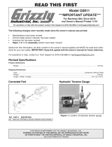
Figure 19. Model G9744Z2 blade selection and speed chart.
The Model G9744Z2 uses 121
1
⁄2" x 1" bandsaw
blades.
Selecting the right blade for the job depends
on a variety of factors, such as the type of
material being cut, hardness of the material,
material shape, machine capability, and operator
technique.
The chart below is a basic starting point for choos-
ing blade type based on teeth per inch (TPI) for
variable-tooth-pitch blades and for standard raker
type bi-metal blades/HSS blades. However, for
exact specifications of bandsaw blades, contact
the blade manufacturer.
To select the correct blade TPI:
1.
Measure the material thickness. This mea-
surement is the length of cut taken from
where the tooth enters the workpiece, sweeps
through, and exits the workpiece.
2.
Refer to the "Material Width/Diameter" row
of the blade selection chart in Figure 19 and
read across to find your workpiece thickness
you need to cut.
3.
Refer to the "Material Shapes" row and find
the shape and material to be cut.
4.
In the applicable row, read across to the right
and find the box where the row and column
intersect. Listed in the box is the minimum
TPI recommended for the variable tooth pitch
blades.
5.
The "Cutting Speed Rate Recommendation"
section of the charts offers guidelines for vari-
ous metals, given in feet per minute (speed
FPM) and meters per minute in parenthesis.
Choose the speed closest to the number
shown in the chart.
Replaces Manual Page 23

Model G9744Z2 (Mfd. Since 10/13)
-5-
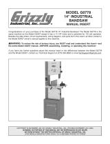
Electrical Components
Figure 47. Limit switch (SQ1).
Figure 50. Pump motor wiring and capacitor
(M2).
Figure 48. Junction box (M1).
Figure 49. Control panel wiring.
SB4
SB1
SB3
L
Figure 51. Contactor & relay electrical box.
(KM2)
Contactor
(KM1)
Contactor
Fuse
(FU 2A)
(KM1)
Relay
(TC)
Transformer
Figure 52. Circuit breaker wiring.
Replaces Manual Page 38

-6-
Model G9744Z2 (Mfd. Since 10/13)
Parts Breakdown
337
354-7
222-3
217
208
B
A
212
218
B
214
200
211
206
A
C
B
212
213
216
215
C
221
207
202
201
205
204
222-5
B
A
A
345-3
220-5
220-4
220-3
220-2
220-6
220-1
355-1
G
302-2
F
304
305
303
209
219
210
301
302-1
300
302
H
314-4
314
313
312
314-3
318
317
310
309
308
307
316-1
311
316
360-1
357
355
356
368
362
361
366
367
360
359
358
H
314-1
314-2
363
354-10
354-3
F
371
G
369
370
354-4
354-5
364
365
345-4
328
330
329
333
332
334
330-1
E
331
321
223-1
222-6
224
226
225
222-1
222-2
222-4
320
324
306
315
315-1
306-1
323
314-6
314-5
326
327
353
322
325
319
342
351
335
343
352
345-1
345-2
345
336
350
348
349
340
341
374
372
373
375
376
354-8
354-6
377
354-2
354-9
354-1
338
339
309-1
K
L
134
133
354-11
220-7
354-12
620
623
624
625
MODEL G9744Z2
10" x 18"
METAL CUTTING BANDSAW
MOTOR: 1-1/2 HP, 220V, 1-PH, 1725 RPM
FULL-LOAD CURRENT RATING: 15.5A
BLADE SPEEDS: 114, 196, 288, 377 FPM
BLADE LENGTH: 121-1/2"
MAX. ROUND CUT AT 90°: 10"
MAX. RECT. WIDTH AT 90°: 18"
MAX. RECT. HEIGHT AT 90° (AT 18"W): 5"
ANGLE CUTS: 45˚ to 90˚
COOLANT CAPACITY: 1-1/2 GALLONS
WEIGHT: 705 LBS.
TO REDUCE THE RISK OF SERIOUS INJURY WHEN OPERATING THIS
MACHINE:
1. READ AND UNDERSTAND MANUAL BEFORE STARTING MACHINE.
2. ALWAYS WEAR EYE PROTECTION AND RESPIRATOR.
3. PLUG POWER CORD INTO GROUNDED OUTLET ONLY.
4. DO NOT USE UNTIL COMPLETELY ASSEMBLED, ADJUSTED AND
INSTALLED ACCORDING TO INSTRUCTIONS, AND ALL CONTROLS
ARE UNDERSTOOD.
5. NEVER POSITION FINGERS OR THUMBS IN LINE WITH CUT.
6. COMPLETELY SUPPORT WORKPIECE DURING WHEN CUTTING.
7. DO NOT WEAR LOOSE CLOTHING, GLOVES OR JEWELRY, AND
SECURE LONG HAIR TO AVOID ENTANGLEMENT INJURIES.
8. ALWAYS USE RECOMMENDED SPEEDS AND FEEDS FOR BLADE AND
WORKPIECE MATERIAL.
9. KEEP ALL GUARDS IN PLACE AT ALL TIMES.
10. DISCONNECT POWER BEFORE SETTING UP OR ADJUSTING.
11. DO NOT EXPOSE TO RAIN OR DAMPNESS.
12. DO NOT OPERATE UNDER THE INFLUENCE OF DRUGS OR ALCOHOL.
220
222
354
338-1
338-2
338-5
338-3
338-7
338-4
338-6

Model G9744Z2 (Mfd. Since 10/13)
-7-
Parts Breakdown
G9744Z2
626
615
16-4
121
132
14
26-1
6-2
6-3
6-1
123
122
36
130
128
129
126
124
125
5
24-1
24
16-6
16-5
16-3
16
16-2
16-7
16-8
16-9
39
48
57
7
61
58
60
55
56
42
37
38
62
59
8
15
13
9
45
12
46
43
44
47
72
30
74
75
74-1
73
40
29
41
31
71-1
117
54
53
50
51
49
52
35
33
32
E
34
71
616
604
610
611
609
608
603
606
605
612
613
614
6-4V2
6-6
6V2
6-5
17-1
17-3
26
6-7
63
64
617
5-1
5-2
5-3
5-4
5-5

-8-
Model G9744Z2 (Mfd. Since 10/13)
Parts List
REF PART # DESCRIPTION REF PART # DESCRIPTION
5 P9744Z2005 CONTROL BOX ASSEMBLY 51 P9744Z2051 REAR VISE JAW
6V2 P9744Z2006V2 PUMP SET 1/8HP 110/220V V2.07.12 52 P9744Z2052 SET SCREW M6-1 X 10
6-1 P9744Z2006-1 CUTTING FLUID TANK 53 P9744Z2053 BUSHING
6-2 P9744Z2006-2 HOSE13X19-350MM 54 P9744Z2054 CAP SCREW M10-1.5 X 35
6-3 P9744Z2006-3 COUPLER PT1/2X1/4 55 P9744Z2055 HEX NUT 3/8-16
6-4V2 P9744Z2006-4V2 PUMP 1/8HP 110/220V V2.07.12 56 P9744Z2056 FLAT WASHER 3/8
6-5 P9744Z2006-5 FLAT WASHER 1/4 57 P9744Z2057 SPRING HANDLE BRACKET
6-6 P9744Z2006-6 PHLP HD SCR 1/4-20 X 5/8 58 P9744Z2058 SPRING ADJUSTING ROD
6-7 P9744Z2006-7 HOSE CLAMP 19MM 59 P9744Z2059 EXTENSION SPRING
7 P9744Z2007 PIVOT SHAFT 60 P9744Z2060 HEX BOLT 5/16-18 X 3/4
8 P9744Z2008 CYLINDER ASSEMBLY 61 P9744Z2061 FLAT WASHER 5/16
9 P9744Z2009 EXT RETAINING RING 18MM 62 P9744Z2062 HEX NUT 5/16-18
12 P9744Z2012 CYLINDER UPPER BRACKET 63 P9744Z2063 FLAT WASHER 10MM
13 P9744Z2013 LOCK WASHER 5/16 64 P9744Z2064 LOCK WASHER 10MM
14 P9744Z2014 CAP SCREW M8-1.25 X 30 71 P9744Z2071 LIMIT SWITCH SUPPORT
15 P9744Z2015 HEX BOLT M10-1.5 X 50 71-1 P9744Z2071-1 FLAT WASHER 6MM
16 P9744Z2016 WORK STOP SET 72 P9744Z2072 CAP SCREW M6-1 X 12
16-2 P9744Z2016-2 SET SCREW M6-1 X 10 73 P9744Z2073 SAFETY SWITCH
16-3 P9744Z2016-3 DISTANCE SET ROD 74 P9744Z2074 FLAT WASHER 4MM
16-4 P9744Z2016-4 THUMB SCREW 74-1 P9744Z2074-1 HEX NUT M4-.7
16-5 P9744Z2016-5 LOCK WASHER 1/4 75 P9744Z2075 PHLP HD SCR M4-.7 X 30
16-6 P9744Z2016-6 SUPPORT ROD 117 P9744Z2117 PIVOT SHAFT
16-7 P9744Z2016-7 DISTANCE SET BRACKET 121 P9744Z2121 CUTTING FLUID PAN
16-8 P9744Z2016-8 HEX NUT M10-1.5 122 P9744Z2122 PHLP HD SCR M6-1 X 10
16-9 P9744Z2016-9 HEX BOLT M10-1.5 X 25 123 P9744Z2123 LOCK WASHER 1/4
17-1 P9744Z2017-1 HANDWHEEL 124 P9744Z2124 HEX BOLT M6-1 X 15
17-3 P9744Z2017-3 KEY 5 X 5 X 15 125 P9744Z2125 FILTER
24 P9744Z2024 EXT TOOTH WASHER 10MM 126 P9744Z2126 HEX NUT M6-1
24-1 P9744Z2024-1 SPANNER NUT M10-1.25 128 P9744Z2128 HEX NUT M8-1.25
26 P9744Z2026 PIVOT BRACKET 129 P9744Z2129 FLAT WASHER 5/16
26-1 P9744Z2026-1 PIVOT SPACER 130 P9744Z2130 HEX BOLT M8-1.25 X 40
29 P9744Z2029 POSITION BRACKET 132 P9744Z2132 HEX BOLT M6-1 X 50
30 P9744Z2030 FLAT WASHER 5/16 133 P9744Z2133 FLAT WASHER 6MM
31 P9744Z2031 HEX BOLT M8-1.25 X 20 134 P9744Z2134 LOCK WASHER 6MM
32 P9744Z2032 REAR PIVOT BRACKET 200 P9744Z2200 FRONT BLADE GUARD
33 P9744Z2033 BUSHING 201 P9744Z2201 SAW DIRECTION LABEL
34 P9744Z2034 LOCK WASHER 10MM 202 P9744Z2202 KNOB M6-1 X 10
35 P9744Z2035 HEX BOLT M10-1.5 X 35 204 P9744Z2204 HEX BOLT M8-1.25 X 25
36 P9744Z2036 BASE 205 P9744Z2205 LOCK WASHER 8MM
37 P9744Z2037 PHLP HD SCR M5-.8 X 8 206 P9744Z2206 FLAT WASHER 8MM
38 P9744Z2038 ANGLE SCALE 207 P9744Z2207 BLADE GUIDE KNOB
39 P9744Z2039 SET SCREW M8-1.25 X 10 208 P9744Z2208 FLAT WASHER 10MM
40 P9744Z2040 HEX NUT M8-1.25 209 P9744Z2209 BLADE GUIDE ARM
41 P9744Z2041 HEX BOLT M8-1.25 X 45 210 P9744Z2210 GIB
42 P9744Z2042 FRONT VISE JAW 211 P9744Z2211 EXT RETAINING RING 8MM
43 P9744Z2043 BUSHING 212 P9744Z2212 BALL BEARING 608-2RS
44 P9744Z2044 FLAT WASHER 10MM 213 P9744Z2213 SHORT ECCENTRIC SHAFT
45 P9744Z2045 CAP SCREW M10-1.5 X 35 214 P9744Z2214 LONG ECCENTRIC SHAFT
46 P9744Z2046 FLAT WASHER 10MM 215 P9744Z2215 CAP SCREW M6-1 X 20
47 P9744Z2047 VISE LOCK KNOB 216 P9744Z2216 CARBIDE GUIDE
48 P9744Z2048 SET SCREW M8-1.25 X 30 217 P9744Z2217 BEARING SHAFT
49 P9744Z2049 FLAT WASHER 10MM 218 P9744Z2218 SET SCREW M6-1 X 5
50 P9744Z2050 VISE FENCE LOCK KNOB 219 P9744Z2219 UPPER BLADE GUIDE BLOCK

Model G9744Z2 (Mfd. Since 10/13)
-9-
Parts List
REF PART # DESCRIPTION REF PART # DESCRIPTION
220 P9744Z2220 VALVE ASSEMBLY 319 P9744Z2319 SET SCREW M8-1.25 X 20
220-1 P9744Z2220-1 CUTTING FLUID VALVE 320 P9744Z2320 HEX BOLT M12-1.75 X 30
220-2 P9744Z2220-2 HOSE 6MM 321 P9744Z2321 LOCK WASHER 12MM
220-3 P9744Z2220-3 HOSE FITTING 322 P9744Z2322 DRIVE WHEEL WASHER
220-4 P9744Z2220-4 HOSE CLIP 323 P9744Z2323 KEY 8 X 8 X 30
220-5 P9744Z2220-5 LOCK WASHER 6MM 324 P9744Z2324 BLADE 1 X 1/32 X 121-1/2
220-6 P9744Z2220-6 BUTTON HD CAP SCR M6-1 X 12 325 P9744Z2325 DRIVE WHEEL
220-7 P9744Z2220-7 HOSE CLAMP 12MM 326 P9744Z2326 CAP SCREW M10-1.5 X 20
221 P9744Z2221 LOWER BLADE GUIDE BLOCK 327 P9744Z2327 LOCK WASHER 10MM
222 P9744Z2222 BRUSH ASSEMBLY 328 P9744Z2328 GEARBOX ASSEMBLY 30:1 DRIVE
222-1 P9744Z2222-1 BRUSH SUPPORT BRACKET 329 P9744Z2329 HEX NUT M10-1.5
222-2 P9744Z2222-2 BLADE BRUSH 330 P9744Z2330 THREADED ROD END M10
222-3 P9744Z2222-3 FLAT WASHER 6MM 330-1 P9744Z2330-1 KNOB
222-4 P9744Z2222-4 HEX NUT M6-1 331 P9744Z2331 HEX NUT M12-1.75
222-5 P9744Z2222-5 HEX BOLT M6-1 X 35 332 P9744Z2332 CAP SCREW M10-1.5
222-6 P9744Z2222-6 HEX BOLT M6-1 X 10 333 P9744Z2333 SHAFT
223-1 P9744Z2223-1 FLAT WASHER 6MM 334 P9744Z2334 MOTOR PLATE
224 P9744Z2224 BUTTON HD CAP SCR M6-1 X 12 335 P9744Z2335 MOTOR BRACKET
225 P9744Z2225 REAR BLADE GUARD 336 P9744Z2336 FLAT WASHER 6MM
226 P9744Z2226 HEX NUT M6-1 337 P9744Z2337 HEX BOLT M6-1 X 20
300 P9744Z2300 CAP SCREW M8-1.25 X 15 338 P9744Z2338 MOTOR 1.5HP 110/220V 60HZ
301 P9744Z2301 HANDLE 338-1 P9744Z2338-1 MOTOR FAN COVER
302 P9744Z2302 KNOB M6-1 X 10 338-2 P9744Z2338-2 MOTOR FAN
302-1 P9744Z2302-1 FLAT WASHER 5MM 338-3 P9744Z2338-3 CAPACITOR COVER
302-2 P9744Z2302-2 BUTTON HD CAP SCR M5-.8 X 10 338-4 P9744Z2338-4 START CAPACITOR 800UF 125VAC
303 P9744Z2303 REAR BLADE COVER 338-5 P9744Z2338-5 CONTACT PLATE
304 P9744Z2304 LOCK WASHER 8MM 338-6 P9744Z2338-6 CENTRIFUGAL SWITCH
305 P9744Z2305 HEX NUT M8-1.25 338-7 P9744Z2338-7 JUNCTION BOX
306 P9744Z2306 COVER 339 P9744Z2339 KEY 8 X 7 X 30
306-1 P9744Z2306-1 FOAM PAD 340 P9744Z2340 FLAT WASHER 8MM
307 P9744Z2307 HEX BOLT M8-1.25 X 20 341 P9744Z2341 HEX BOLT M8-1.25 X 15
308 P9744Z2308 STEEL WASHER 16 X 30 X 3MM 342 P9744Z2342 HEX BOLT M6-1 X 10
309 P9744Z2309 TAPERED ROLLER BEARING 6025 343 P9744Z2343 FLAT WASHER 6MM
309-1 P9744Z2309-1 INT RETAINING RING 52MM 345 P9744Z2345 MOTOR PULLEY COVER ASSEMBLY
310 P9744Z2310 IDLER WHEEL 345-1 P9744Z2345-1 KNOB M6-1 X 10
311 P9744Z2311 SHAFT 345-2 P9744Z2345-2 FLAT WASHER 6MM
312 P9744Z2312 HANDLE 345-3 P9744Z2345-3 BLADE COVER BRACKET
313 P9744Z2313 HEX NUT 3/8-16 345-4 P9744Z2345-4 CAP SCREW M6-1 X 10
314 P9744Z2314 SAW BOW 348 P9744Z2348 SPINDLE PULLEY
314-1 P9744Z2314-1 PIPE CONNECTOR 1/2 NPT 349 P9744Z2349 SET SCREW M8-1.25 X 10
314-2 P9744Z2314-2 CUTTING FLUID HOSE 350 P9744Z2350 V-BELT A32
314-3 P9744Z2314-3 RUBBER FOOT M8-1.25 X 40 351 P9744Z2351 MOTOR PULLEY
314-4 P9744Z2314-4 HEX NUT M8-1.25 352 P9744Z2352 SET SCREW M8-1.25 X 10
314-5 P9744Z2314-5 FILTER 353 P9744Z2353 SPEED INDICATOR DIAL
314-6 P9744Z2314-6 BUTTON HD CAP SCR M5-.8 X 10 354 P9744Z2354 3 WAY VALVE ASSEMBLY
315 P9744Z2315 COVER 354-1 P9744Z2354-1 HOSE CLAMP 12MM
315-1 P9744Z2315-1 KNOB M6-1 X 10 354-2 P9744Z2354-2 STRAIGHT CONNECTOR 1/4 NPT
316 P9744Z2316 SCALE 354-3 P9744Z2354-3 L CONNECTOR
316-1 P9744Z2316-1 RIVET 2 X 5MM 354-4 P9744Z2354-4 HOSE CLAMP 19MM
317 P9744Z2317 CAP SCREW M12-1.75 X 20 354-5 P9744Z2354-5 CUTTING FLUID HOSE 1/4"ID X 31-1/2"
318 P9744Z2318 COLUMN 354-6 P9744Z2354-6 3 WAY VALVE

-10-
Model G9744Z2 (Mfd. Since 10/13)
Parts List
REF PART # DESCRIPTION REF PART # DESCRIPTION
354-7 P9744Z2354-7 STRAIGHT CONNECTOR 1/4 NPT 372 P9744Z2372 HEX BOLT M6-1 X 12
354-8 P9744Z2354-8 CAP SCREW M6-1 X 30 373 P9744Z2373 FLAT WASHER 6MM
354-9 P9744Z2354-9 CUTTING FLUID HOSE 1/4"ID X 52" 374 P9744Z2374 CONTROL BOX
354-10 P9744Z2354-10 CUTTING FLUID HOSE 1/4"ID X 12-1/2" 375 P9744Z2375 FLAT HD SCR M6-1 X 12
354-11 P9744Z2354-11 HOSE CLIP 376 P9744Z2376 CONTROL PANEL
354-12 P9744Z2354-12 PHLP HD SCR M6-1 X 10 377 P9744Z2377 PHLP HD SCR M5-.8 X 8
355 P9744Z2355 BLADE TENSION HANDWHEEL 603 P9744Z2603 VISE LEADSCREW PILLOW BLOCK
355-1 P9744Z2355-1 BLADE TENSION HANDLE 604 P9744Z2604 FLAT WASHER 12MM
356 P9744Z2356 BALL BEARING 51203 605 P9744Z2605 HEX BOLT 3/8-16 X 1-1/4
357 P9744Z2357 TENSION INDICATION RING 606 P9744Z2606 FLAT WASHER 3/8
358 P9744Z2358 CONCAVE WASHER 16MM 608 P9744Z2608 VISE QUICK RELEASE HUB
359 P9744Z2359 BLADE LEADSCREW 609 P9744Z2609 VISE QUICK RELEASE LEVER
360 P9744Z2360 BLADE WHEEL BASE WAY 610 P9744Z2610 LEVER CAP
360-1 P9744Z2360-1 TENSION SCALE 611 P9744Z2611 VISE LEADSCREW BEARING
361 P9744Z2361 SET SCREW M6-1 X 16 612 P9744Z2612 VISE LEADSCREW WASHER 12MM
362 P9744Z2362 BLADE WHEEL BASE 613 P9744Z2613 COMPRESSION SPRING
363 P9744Z2363 HEX NUT M16-2 614 P9744Z2614 VISE LEADSCREW
364 P9744Z2364 FLAT WASHER 8MM 615 P9744Z2615 VISE LEADSCREW NUT
365 P9744Z2365 CAP SCREW M8-1.25 X 20 616 P9744Z2616 VISE LEADSCREW WASHER 1/2"
366 P9744Z2366 THREADED INSERT 617 P9744Z2617 ELECTRICITY WARNING LABEL
367 P9744Z2367 LOCK WASHER 10MM 620 P9744Z2620 MOTOR LABEL
368 P9744Z2368 HEX BOLT M10-1.5 X 60 623 P9744Z2623 CUTTING SELECTION
369 P9744Z2369 PRESS BOARD 624 P9744Z2624 BLADE TENSION LABEL
370 P9744Z2370 LOCK WASHER 8MM 625 P9744Z2625 MACHINE ID LABEL
371 P9744Z2371 CAP SCREW M8-1.25 X 10 626 P9744Z2626 MODEL NUMBER LABEL


MODEL G9744Z
10"x18" Metal Cutting Bandsaw
OWNER'S MANUAL
COPYRIGHT © JULY, 2006 BY GRIZZLY INDUSTRIAL, INC.
WARNING: NO PORTION OF THIS MANUAL MAY BE REPRODUCED IN ANY SHAPE
OR FORM WITHOUT THE WRITTEN APPROVAL OF GRIZZLY INDUSTRIAL, INC.
#PC8343 PRINTED IN TAIWAN

This manual provides critical safety instructions on the proper setup,
operation, maintenance, and service of this machine/tool. Save this
document, refer to it often, and use it to instruct other operators.
Failure to read, understand and follow the instructions in this manual
may result in fire or serious personal injury—including amputation,
electrocution, or death.
The owner of this machine/tool is solely responsible for its safe use.
This responsibility includes but is not limited to proper installation in
a safe environment, personnel training and usage authorization,
proper inspection and maintenance, manual availability and compre-
hension, application of safety devices, cutting/sanding/grinding tool
integrity, and the usage of personal protective equipment.
The manufacturer will not be held liable for injury or property damage
from negligence, improper training, machine modifications or misuse.
Some dust created by power sanding, sawing, grinding, drilling, and
other construction activities contains chemicals known to the State
of California to cause cancer, birth defects or other reproductive
harm. Some examples of these chemicals are:
• Lead from lead-based paints.
• Crystalline silica from bricks, cement and other masonry products.
• Arsenic and chromium from chemically-treated lumber.
Your risk from these exposures varies, depending on how often you
do this type of work. To reduce your exposure to these chemicals:
Work in a well ventilated area, and work with approved safety equip-
ment, such as those dust masks that are specially designed to filter
out microscopic particles.

Table of Contents
INTRODUCTION ............................................................................................................................... 3
Foreword .................................................................................................................................... 3
Contact Info ................................................................................................................................ 3
Machine Data Sheet ................................................................................................................... 4
Identification ............................................................................................................................... 6
Control Panel.............................................................................................................................. 7
SECTION 1: SAFETY ....................................................................................................................... 8
Safety Instructions for Machinery ............................................................................................... 8
Additional Safety Instructions for Metal Cutting Bandsaws ..................................................... 10
SECTION 2: CIRCUIT REQUIREMENTS ...................................................................................... 11
220V Single-Phase................................................................................................................... 11
SECTION 3: SETUP ....................................................................................................................... 12
Setup Safety ............................................................................................................................. 12
Items Needed for Setup ........................................................................................................... 12
Unpacking ................................................................................................................................ 12
Inventory ................................................................................................................................... 13
Hardware Recognition Chart .................................................................................................... 14
Clean Up .................................................................................................................................. 15
Site Considerations .................................................................................................................. 15
Moving & Placing Base Unit ..................................................................................................... 16
Mounting to Shop Floor ............................................................................................................ 16
Shipping Bracket ...................................................................................................................... 17
Workstop .................................................................................................................................. 17
Chip Tray .................................................................................................................................. 18
Feed Stop ................................................................................................................................. 18
Recommended Adjustments .................................................................................................... 19
Test Run ................................................................................................................................... 19
SECTION 4: OPERATIONS ........................................................................................................... 20
Operation Safety ...................................................................................................................... 20
Vise .......................................................................................................................................... 20
Blade Guide Arms .................................................................................................................... 22
Blade Selection ........................................................................................................................ 23
Blade Speed ............................................................................................................................. 24
Feed Rate................................................................................................................................. 24
Coolant System ........................................................................................................................ 25
Cutting Fluid ............................................................................................................................ 26
Operation Tips .......................................................................................................................... 27
SECTION 5: ACCESSORIES ......................................................................................................... 28

SECTION 6: MAINTENANCE......................................................................................................... 30
Schedule .................................................................................................................................. 30
Cleaning ................................................................................................................................... 30
Lubrication ................................................................................................................................ 30
SECTION 7: SERVICE ................................................................................................................... 32
Troubleshooting ........................................................................................................................ 32
Blade Change........................................................................................................................... 34
Blade Tension & Tracking ........................................................................................................ 35
Blade Guide Bearings .............................................................................................................. 36
Squaring Blade to Table........................................................................................................... 37
Electrical Components ............................................................................................................. 38
Model G9744Z 220V Wiring Diagram ...................................................................................... 39
Blade Guide Parts Breakdown ................................................................................................. 40
Drive Wheel Parts Breakdown ................................................................................................. 41
Main Parts Breakdown ............................................................................................................. 42
Parts List .................................................................................................................................. 43
WARRANTY AND RETURNS ........................................................................................................ 46

G9744Z Metal Cutting Bandsaw
-3-
Foreword
INTRODUCTION
Contact Info
We are proud to offer the Model G9744Z Metal
Cutting Bandsaw. This machine is part of a grow-
ing Grizzly family of fine metalworking machinery.
When used according to the guidelines set forth in
this manual, you can expect years of trouble-free,
enjoyable operation and proof of Grizzly’s com-
mitment to customer satisfaction.
We are pleased to provide this manual with
the Model G9744Z. It was written to guide you
through assembly, review safety considerations,
and cover general operating procedures. It repre-
sents our effort to produce the best documenta-
tion possible.
The specifications, drawings, and photographs
illustrated in this manual represent the Model
G9744Z as supplied when the manual was pre-
pared. However, owing to Grizzly’s policy of con-
tinuous improvement, changes may be made at
any time with no obligation on the part of Grizzly.
For your convenience, we always keep current
Grizzly manuals available on our website at www.
grizzly.com. Any updates to your machine will be
reflected in these manuals as soon as they are
complete. Visit our site often to check for the lat-
est updates to this manual!
We stand behind our machines! If you have ques-
tions or need help, contact us with the information
below. Before contacting, make sure you get the
serial number and manufacture date from the
machine ID label. This will help us help you faster.
Grizzly Technical Support
1815 W. Battlefield
Springfield, MO 65807
Phone: (570) 546-9663
Email: [email protected]
We want your feedback on this manual. What did
you like about it? Where could it be improved?
Please take a few minutes to give us feedback.
Grizzly Documentation Manager
P.O. Box 2069
Bellingham, WA 98227-2069
Email: [email protected]

-4-
G9744Z Metal Cutting Bandsaw
Machine Data Sheet
MODEL G9744Z 10" X 18" METAL CUTTING BANDSAW
Customer Service #: (570) 546-9663 • To Order Call: (800) 523-4777 • Fax #: (800) 438-5901
MACHINE DATA
SHEET
Product Dimensions:
Weight .............................................................................................................................................................770 lbs.
Length/Width/Height .................................................................................................................... 68 x 24 x 41-1/2 in.
Foot Print (Length/Width) ............................................................................................................................ 47 x 19 in.
Shipping Dimensions:
Type ...................................................................................................................................................Wood Slat Crate
Content ............................................................................................................................................................Machine
Weight ..............................................................................................................................................................860 lbs.
Length/Width/Height ................................................................................................................ 69 x 29-1/2 x 47-1/2 in.
Electrical:
Switch .........................................................................................................................................Push Button ON/OFF
Switch Voltage ..................................................................................................................................................... 220V
Cord Length ........................................................................................................................................................... 5 ft.
Cord Gauge .................................................................................................................................................. 14 gauge
Recommended Breaker Size ........................................................................................................................... 20 amp
Plug ..........................................................................................................................................................................No
Motors:
Main
Type..................................................................................................................TEFC Capacitor Start Induction
Horsepower ................................................................................................................................................ 2 HP
Voltage....................................................................................................................................................... 220V
Prewired .....................................................................................................................................................220V
Phase ....................................................................................................................................................... Single
Amps ............................................................................................................................................................15A
Speed ................................................................................................................................................ 1725 RPM
Cycle .........................................................................................................................................................60 Hz
Number Of Speeds .......................................................................................................................................... 1
Power Transfer .......................................................................................................................................... Gear
Bearings ...................................................................................................................... Shielded and Lubricated
Main Specifications:
Operation Info
Blade Speeds .............................................................................................................. 114, 196, 288, 377 FPM
Std. Blade Length ............................................................................................................................. 129-3/8 in.

G9744Z Metal Cutting Bandsaw
-5-
Cutting Capacities
Angle Cuts ............................................................................................................................................ 45°–90°
Vise Jaw Depth ................................................................................................................................... 12-1/2 in.
Vise Jaw Height .......................................................................................................................................... 5 in.
Max Capacity Rect. Height At 90° .............................................................................................................. 5 in.
Max Capacity Rect. Width At 90° ....................................................................................................... 18-3/8 in.
Max Capacity Rnd. Width At 90° .............................................................................................................. 10 in.
Max Capacity Rect. Height At 45° .............................................................................................................. 6 in.
Max Capacity Rect. Height At 30° ............................................................................................................ 10 in.
Max Capacity Rect. Width At 30° ............................................................................................................. 14 in.
Max Capacity Rnd. At 30°......................................................................................................................... 10 in.
Max Capacity Rect. Width At 45° ......................................................................................................... 9-3/8 in.
Max Capacity Rnd. At 45°........................................................................................................................... 6 in.
Construction
Table Construction ..................................................................................................Precision Ground Cast Iron
Wheel Construction Upper ..................................................................................................Machined Cast Iron
Wheel Construction Lower ..................................................................................................Machined Cast Iron
Body Construction ................................................................................................................................Cast Iron
Base Construction ................................................................................................................. Pre-Formed Steel
Wheel Cover Construction .................................................................................................... Pre-Formed Steel
Paint ........................................................................................................................................................ Epoxy
Other
Wheel Size ................................................................................................................................................ 13 in.
Blade Guides Upper ........................................................................................................................Ball Bearing
Blade Guides Lower ........................................................................................................................Ball Bearing
Coolant Capacity ................................................................................................................................. 2-1/2 gal.
Table Info
Floor To Cutting Area Height .................................................................................................................... 23 in.
Other Specifications:
ISO Factory ................................................................................................................................................... ISO 9001
Country Of Origin ..............................................................................................................................................Taiwan
Warranty .............................................................................................................................................................1 Year
Serial Number Location ......................................................................................................................Grizzly ID Label
Assembly Time ...........................................................................................................................................15 minutes
Features:
Centralized Control Panel on Top of the Saw Bow
Heavy-duty Steel Base
Adjustable Hydraulic Downfeed
Worm Gear Box has Hardened and Ground Gears
Quick Release Vise for Fast Job Changes
Miter Cutting Ability
Blade Wheels have Heavy-duty Ball Bearings
Magnetic Safety Switch
Coolant Pump and Reservoir

-6-
G9744Z Metal Cutting Bandsaw
Figure 1. G9744Z machine identification.
Identification
A
C
B
D
E
H
I
J
K
M
A. Blade Tension Handwheel
B. Lift Handle
C. Vise Handwheel
D. Coolant Drip Pan
E. Work Stop
F. Pulley Cover
G. Control Panel
H. Blade Guide Scale
I. Blade Guide Knob
J. Coolant Valve Control
K. Bow
L. Blade Guides
M. Wheel Covers
N. Chip Tray
F
M
N
G
L

G9744Z Metal Cutting Bandsaw
-7-
Control Panel
Figure 2. G9744Z control panel.
A
B C D
E
F
A. Coolant Pump Switch: Turns the coolant
pump ON.
B. EMERGENCY STOP/OFF Button: Interrupts
power to the system and turns the motor
OFF. Twist the button until it pops out to re-
energize the system. Also works as a stan-
dard OFF button.
Note: The bandsaw has an automatic shut-
off (limit switch) that turns the motor and
coolant pump OFF at the bottom of the cut.
C. START Button: Turns the motor ON.
D. Power Light: When lit, indicates that system
is energized and machine is ready to oper-
ate.
E. Feed Rate Dial: Fine tunes the feed rate by
controlling the hydraulic valve. Range is from
0 (slowest) to 9 (fastest).
F. Feed Control Knob: Turning the knob to the
left lowers the bow at the feed rate you have
set. Turning the knob to the right locks the
bow in position.
/