Page is loading ...

Visit our website at
www.MillerWelds.com
RCAP-1
Processes
Description
Multiprocess Welding
Remote Control Pendant
OM-535B August 1992
Eff. w/Style Number KB-49

Miller Electric manufactures a full line
of welders and welding related equipment.
For information on other quality Miller
products, contact your local Miller distributor
to receive the latest full line catalog or
individual catalog sheets. To locate your nearest
distributor or service agency call 1-800-4-A-Miller,
or visit us at www.MillerWelds.com on the web.
Thank you and congratulations on choosing Miller. Now
you can get the job done and get it done right. We know
you don’t have time to do it any other way.
That’s why when Niels Miller first started building arc
welders in 1929, he made sure his products offered
long-lasting value and superior quality. Like you, his
customers couldn’t afford anything less. Miller products
had to be more than the best they could be. They had to
be the best you could buy.
Today, the people that build and sell Miller products continue the
tradition. They’re just as committed to providing equipment and service
that meets the high standards of quality and value established in 1929.
This Owner’s Manual is designed to help you get the most out of your
Miller products. Please take time to read the Safety precautions. They will
help you protect yourself against potential hazards on the worksite. We’ve
made installation and operation quick and easy.
With Miller you can count on years of reliable
service with proper maintenance. And if for
some reason the unit needs repair, there’s a
Troubleshooting section that will help you
figure out what the problem is. The parts list
will then help you to decide which exact part
you may need to fix the problem. Warranty and
service information for your particular model
are also provided.
Miller is the first welding
equipment manufacturer in
the U.S.A. to be registered to
the ISO 9001 Quality System
Standard.
Working as hard as you do
– every power source from
Miller is backed by the most
hassle-free warranty in the
business.
From Miller to You
Miller offers a Technical
Manual which provides
more detailed service and
parts information for your
unit. To obtain a Technical
Manual, contact your local
distributor. Your distributor
can also supply you with
Welding Process Manuals
such as SMAW, GTAW,
GMAW, and GMAW-P.

OM-535 Page 1
SECTION 1 – SAFETY SIGNAL WORDS
mod1.1 9/91
The following safety alert symbol and signal words are used throughout this manual to call attention to and identify
different levels of hazard and special instructions.
WARNING
WARNING statements identify procedures or practices which must be followed to avoid serious personal
injury or loss of life.
CAUTION
CAUTION statements identify procedures or practices which must be followed to avoid minor personal
injury or damage to this equipment.
IMPORTANT: statements identify special instructions necessary for the most efficient operation of this equipment.
SECTION 2 – SPECIFICATIONS
Table 2-1. Pendant
Specification Description
Overall Dimensions Height: 5-1/2 in. (140 mm); Width: 2-3/4 in. (70 mm); Depth: 2-1/2 in. (64 mm)
Input Power Cord With Plug 15 ft. (4.6 m)
Additional Required Equipment Welding Power Source With Suitable Remote 17 Receptacle
Welding Power Source Type Needed Constant Current/Constant Voltage (CC/CV) DC
Welding Processes Shielded Metal Arc (SMAW), Gas Metal Arc (GMAW), Flux Cored Arc (FCAW), Gas Tungsten Arc
(GTAW), Gas Metal Arc - Pulsed (GMAW-P) Welding, Air Carbon Arc Cutting And Gouging (CAC-A)

OM-535 Page 2
SECTION 3 – INSTALLATION
WARNING
ELECTRIC SHOCK can kill.
• Do not touch live electrical parts.
• Turn OFF welding power source, and place pendant CONTACTOR switch in OFF position before making connections.
swarn3.1* 10/91
Turn OFF welding power source.
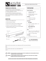
1 Welding Power Source
2 17-Socket Receptacle
3 Plug PLG1 From Pendant
Insert plug into matching 17-socket
receptacle on welding power
source, and tighten threaded collar.
4 Mounting Bracket
5 User-Supplied Mounting
Hardware
ST-156 635
1
2
3
4
5
Figure 3-1. Connections To Welding Power Source And Optional Wall-Mounting Procedure

OM-535 Page 3
SECTION 4 – OPERATION
ELECTRIC SHOCK can kill.
• Always wear dry insulating gloves.
• Insulate yourself from work and ground.
• Do not touch live electrical parts.
• Keep all panels and covers securely in place.
FUMES AND GASES can be hazardous
to your health.
• Keep your head out of the fumes.
• Ventilate area, or use breathing device.
• Read Material Safety Data Sheets (MSDSs) and
manufacturer’s instructions for material used.
WELDING can cause fire or explosion.
• Do not weld near flammable material.
• Watch for fire; keep extinguisher nearby.
• Do not locate unit over combustible surfaces.
• Do not weld on closed containers.
• Allow work and equipment to cool before handling.
ARC RAYS can burn eyes and skin;
NOISE can damage hearing.
• Wear welding helmet with correct shade of filter.
• Wear correct eye, ear, and body protection.
MOVING PARTS can cause injury.
• Keep away from moving parts.
• Keep all doors, panels, covers, and guards closed
and securely in place.
WELDING WIRE can cause puncture
wounds.
• Do not press gun trigger until instructed to do so.
• Do not point gun toward any part of the body, other
people, or any metal when threading welding wire.
MAGNETIC FIELDS FROM HIGH CUR-
RENTS can affect pacemaker operation.
• Pacemaker wearers keep away.
• Wearers should consult their doctor before going
near arc welding, gouging, or spot welding opera-
tions.
See Safety Precautions at beginning of welding power
source Owner’s Manual for basic welding safety infor-
mation.
WARNING
swarn6.1* 10/91
SA-106 543-B
1 Output Control
2 Arc Control/Inductance Con-
trol
3 Contactor Switch
4 CC/CV Switch
Every month check labels, cord,
and plug for damage.
1
2
3
4
Figure 4-1. Controls
1 Insulating Gloves
2 Safety Glasses With Side
Shields
3 Welding Helmet
Wear dry insulating gloves, safety
glasses with side shields, and a
welding helmet with a correct shade
of filter (see ANSI Z49.1).
sb3.1 10/91
123
Figure 4-2. Safety Equipment

OM-535 Page 4
1 CC/CV Switch
Use switch to select type of weld
output. Use constant current (CC)
for GTAW, SMAW, GMAW-P, and
CAC-A. Use constant voltage (CV)
for GMAW and FCAW.
Ref. TC-109 369-B
1
Figure 4-3. CC/CV Switch
1 Output Control
Use CC/CV switch to select weld
amperage (CC) or voltage (CV). In
CC, adjust control according to am-
perage (A) scale. In CV, adjust con-
trol according to voltage (V) scale.
1
Figure 4-4. Output Control
1 Arc Control/Inductance Con-
trol
Use CC/CV Switch (see
Figure 4-3) to select weld amper-
age (CC) or voltage (CV). If CC po-
sition is selected, adjust Arc Force
(Dig). If CV, adjust Inductance.
Numbers around control are for ref-
erence only.
Arc Control
For SMAW (Stick Electrode) weld-
ing, use control to help start an arc
or make vertical or overhead welds
(control increases short-circuit am-
perage).
When set at 0, short-circuit amper-
age is the same as normal welding
amperage.
When setting increases, short-cir-
cuit amperage increases to help arc
starting.
Set at 0 for GTAW welding.
Inductance Control
Use this control to change weld out-
put inductance for GMAW and
FCAW. Inductance determines the
“wetness” of the weld puddle.
1
Figure 4-5. Arc Control/Inductance Control

OM-535 Page 5
1 Contactor Switch
Use this switch to select way of
controlling welding power source
output.
If open-circuit voltage is desired
whenever the welding power
source is energized, place switch in
ON position. Use this position for
SMAW and CAC-A.
If contactor control by means of a
wire feeder or remote device is de-
sired, place switch in OFF position.
Use this position for GMAW, FCAW
and GTAW.
1
Figure 4-6. Contactor Switch
1 Welding Power Source
For ARC PAK 350:
Set 14/17 switch to 17 position.
For MAXTRON 450:
Set Amperage/Voltage Control
switch to REMOTE 17 position.
Set Output/Contactor switch to RE-
MOTE 14/17 position.
Set Arc Force/Inductance And CC/
CV Control Switch to REMOTE 17
position.
1
Figure 4-7. Welding Power Source
Install &
Connect
Equipment
Install & Prepare
Wire Feeding
System
Put On
Personal Safety
Equipment
Set Controls
Turn On
Shielding Gas
Turn On Feeder
And Welding
Power Source
Begin Welding
ssb6.1 2/92
Figure 4-8. Sequence Of Gas Metal Arc Welding (GMAW)
Install &
Connect
Equipment
Install & Prepare
Wire Feeding
System
Install Synergic
Pulse Control
Put On
Personal Safety
Equipment
Set Controls
Turn On
Shielding Gas
Turn On Feeder
And Welding
Power Source
Begin Welding
Figure 4-9. Sequence Of Gas Metal Arc Welding - Pulsed (GMAW-P)
Install &
Connect
Equipment
Install & Prepare
Wire Feeding
System
Put On
Personal Safety
Equipment
Set Controls Begin Welding
Turn On Feeder
And Welding
Power Source
Figure 4-10. Sequence Of Flux Cored Arc Welding (FCAW)

OM-535 Page 6
Install &
Connect
Equipment
Install & Connect
High-Frequency
Unit
Select
Tungsten
(See Section 7)
Insert
Tungsten
Into Torch
Put On
Personal Safety
Equipment
Set Controls
Turn On
Shielding Gas
Turn On
High-Frequency
Unit
Turn On
Welding Power
Source
Begin Welding
ssb8.1 2/92
Figure 4-11. Sequence Of Gas Tungsten Arc Welding (GTAW)
Install &
Connect
Equipment
Select
Electrode
Put On
Personal Safety
Equipment
Set Controls
Turn On
Welding Power
Source
Insert
Electrode
Into Holder
Begin Welding
ssb7.1 2/92
Figure 4-12. Sequence Of Shielded Metal Arc Welding (SMAW)
Put On
Personal Safety
Equipment
Set Controls
Install &
Connect
Equipment
Connect
Compressed
Air Supply
Select
Electrode
Turn On
Compressed
Air Supply
Turn On
Welding Power
Source
Begin
Cutting Or
Gouging
ssb7.1* 2/92
Insert
Electrode
Into Holder
Figure 4-13. Sequence Of Air Carbon Arc Cutting And Gouging (CAC-A)
SECTION 5 – TROUBLESHOOTING
WARNING
ELECTRIC SHOCK can kill.
• Do not touch live electrical parts.
• Turn OFF welding power source, and disconnect pendant before inspecting, maintaining, or servicing.
Troubleshooting to be performed only by qualified persons.
Table 5-1. Welding Trouble
Trouble Remedy Section
No weld output. Be sure welding power source POWER switch is ON. – –
Check welding gun and/or wire feeder if applicable. – –
No control of weld output. Check welding power source control settings. Figure 4-7
Be sure plug PLG1 is securely connected to REMOTE 17 recep-
tacle on welding power source.
Figure 3-1
Check pendant cord and replace if necessary. – –
Pendant does not work. Check pendant potentiometers and switches. – –
Erratic weld; incorrect weld characteris-
tics.
Check pendant settings. Figure 4-2,
Figure 4-3,
Figure 4-4,
Figure 4-5
Check wire feed speed at wire feeder if applicable. – –

OM-535 Page 7
SECTION 6 – ELECTRICAL DIAGRAMS
SA-099 207-A
Figure 6-1. Circuit Diagram

OM-535 Page 8
SECTION 7 – TUNGSTEN ELECTRODE
mod2.1 10/91
IMPORTANT: For additional information, see your distributor for a handbook on the Gas Tungsten Arc Welding
(GTAW) process.
7-1. Selecting Tungsten Electrode
Table 7-1. Tungsten Size
Amperage Range - Gas Type♦ - Polarity
Electrode Diameter
DC – Argon – Electrode
Negative/Straight Polarity
DC – Argon – Electrode
Positive/Reverse Polarity
AC – Argon – Using
High Frequency
AC – Argon – Balanced
Wave Using High Freq.
Pure Tungsten
(Green Band)
.010” Up to 15 * Up to 15 Up to 10
.020” 5-20 * 5-20 10-20
.040” 15-80 * 10-60 20-30
1/16” 70-150 10-20 50-100 30-80
3/32” 125-225 15-30 100-160 60-130
1/8” 225-360 25-40 150-210 100-180
5/32” 360-450 40-55 200-275 160-240
3/16” 450-720 55-80 250-350 190-300
1/4” 720-950 80-125 325-450 250-400
2% Thorium Alloyed
Tungsten (Red Band)
.010” Up to 25 * Up to 20 Up to 15
.020” 15-40 * 15-35 5-20
.040” 25-85 * 20-80 20-60
1/16” 50-160 10-20 50-150 60-120
3/32” 135-235 15-30 130-250 100-180
1/8” 250-400 25-40 225-360 160-250
5/32” 400-500 40-55 300-450 200-320
3/16” 500-750 55-80 400-500 290-390
1/4” 750-1000 80-125 600-800 340-525
Zirconium Alloyed Tung-
sten (Brown Band)
.010” * * Up to 20 Up to 15
.020” * * 15-35 5-20
.040” * * 20-80 20-60
1/16” * * 50-150 60-120
3/32” * * 130-250 100-180
1/8” * * 225-360 160-250
5/32” * * 300-450 200-320
3/16” * * 400-550 290-390
1/4” * * 600-800 340-525
♦Typical argon shielding gas flow rates are 15 to 35 cfh (cubic feet per hour).
*Not Recommended.
The figures listed are intended as a guide and are a composite of recommendations from American Welding Society (AWS) and electrode
manufacturers.
S-0009

OM-535 Page 9
7-2. Preparing Tungsten
1 Tungsten Electrode
2 Balled End
Ball end of tungsten before welding
by applying either an ac amperage
slightly higher than what is recom-
mended for a given electrode diam-
eter (see Table 7-1), or a dc elec-
trode positive amperage.
Ref. S-0161
1
1-1/2 Times
2
Electrode Diameter
Figure 7-1. Preparing Tungsten For AC Or DC Electrode Positive (DCEP) Welding
CAUTION
FLYING SPARKS AND HOT METAL can cause injury and start fires.
• Shape tungsten electrode only on grinder with proper guards in a safe location wearing proper face, hand, and body protection.
• Keep flammables away.
warn2.1 9/91
1 Tungsten Electrode
2 Tapered End
Grind end of tungsten on fine grit,
hard abrasive wheel before weld-
ing. Do not use wheel for other jobs
or tungsten can become contami-
nated causing lower weld quality.
3
Ideal Tungsten Preparation – Stable Arc
Ref. S-0162
Ref. S-0161
2-1/2 Times
Electrode Diameter
1
2
1 Stable Arc
2 Flat
Diameter of this flat determines am-
perage capacity.
3 Grinding Wheel
4 Straight Ground
3
1
2
1 Arc Wander
2 Point
3 Grinding Wheel
4 Radial Ground
2
1
4
Ref. S-0162
Wrong Tungsten Preparation – Wandering Arc
4
Figure 7-2. Preparing Tungsten For DC Electrode Negative (DCEN) Welding

OM-535 Page 10
SECTION 8 – PARTS LIST
7
9
SA-106 543-B
12
4
5
6
3
8
Figure 8-1. RCAP-1
Description
Part
No.
Dia.
Mkgs.
099 232
Item
No.
Figure 8-1. RCAP-1
Quantity
1 134 429 CASE SECTION, front/end 1. . . . . . . . . . . . . . . . . . . . . . . . . . . . . . . . . . . . . . . . . . . . . . . . . . . . . . . . .
NAMEPLATE, (order by model and style number) 1. . . . . . . . . . . . . . . . . . . . . . . . . . . . . . . . . . . . . . . . . . . . . . . . . .
2 148 348 CASE SECTION, back/sides/end 1. . . . . . . . . . . . . . . . . . . . . . . . . . . . . . . . . . . . . . . . . . . . . . . . . . . .
3 097 866 PLUG, 17 pin MS-3106A-20-29P 1. . . . . . . . . . . . . . . . . . . . . . . . . . . . . . . . . . . . . . . . . . . . . . . . . . . .
4 073 296 CLAMP, cable 97-3057-12-6 1. . . . . . . . . . . . . . . . . . . . . . . . . . . . . . . . . . . . . . . . . . . . . . . . . . . . . . . .
5 135 304 CABLE, port No. 18 8/c (order by ft) 15ft. . . . . . . . . . . . . . . . . . . . . . . . . . . . . . . . . . . . . . . . . . . . . . . .
6 134 900 STRAIN RELIEF, cable flexible .270-.480 cable 1. . . . . . . . . . . . . . . . . . . . . . . . . . . . . . . . . . . . . . . .
7 S2 079 722 SWITCH, tgl SPDT .4A 2-4VDC 1. . . . . . . . . . . . . . . . . . . . . . . . . . . . . . . . . . . . . . . . . . . . . . . . .
8 S1 011 770 SWITCH, tgl SPDT 5A 125V 1. . . . . . . . . . . . . . . . . . . . . . . . . . . . . . . . . . . . . . . . . . . . . . . . . . . . .
9 097 922 KNOB, pointer 2. . . . . . . . . . . . . . . . . . . . . . . . . . . . . . . . . . . . . . . . . . . . . . . . . . . . . . . . . . . . . . . . . . . .
R1,2 035 897 POTENTIOMETER, C std slot 1/T 2W 1K ohm 2. . . . . . . . . . . . . . . . . . . . . . . . . . . . . . . . . . . . .
BE SURE TO PROVIDE MODEL AND STYLE NUMBER WHEN ORDERING REPLACEMENT PARTS.

Notes

Notes

Warranty Questions?
Call
1-800-4-A-MILLER
for your local
Miller distributor.
miller_warr 7/00
Your distributor also gives
you ...
Service
You always get the fast,
reliable response you
need. Most replacement
parts can be in your
hands in 24 hours.
Support
Need fast answers to the
tough welding questions?
Contact your distributor.
The expertise of the
distributor and Miller is
there to help you, every
step of the way.
Effective January 1, 2000
(Equipment with a serial number preface of “LA” or newer)
This limited warranty supersedes all previous Miller warranties and is exclusive with no other
guarantees or warranties expressed or implied.
LIMITED WARRANTY – Subject to the terms and conditions
below, Miller Electric Mfg. Co., Appleton, Wisconsin, warrants
to its original retail purchaser that new Miller equipment sold
after the effective date of this limited warranty is free of defects
in material and workmanship at the time it is shipped by Miller.
THIS WARRANTY IS EXPRESSLY IN LIEU OF ALL OTHER
WARRANTIES, EXPRESS OR IMPLIED, INCLUDING THE
WARRANTIES OF MERCHANTABILITY AND FITNESS.
Within the warranty periods listed below, Miller will repair or
replace any warranted parts or components that fail due to
such defects in material or workmanship. Miller must be
notified in writing within thirty (30) days of such defect or
failure, at which time Miller will provide instructions on the
warranty claim procedures to be followed.
Miller shall honor warranty claims on warranted equipment
listed below in the event of such a failure within the warranty
time periods. All warranty time periods start on the date that
the equipment was delivered to the original retail purchaser, or
one year after the equipment is sent to a North American
distributor or eighteen months after the equipment is sent to an
International distributor.
1. 5 Years Parts – 3 Years Labor
* Original main power rectifiers
* Inverters (input and output rectifiers only)
2. 3 Years — Parts and Labor
* Transformer/Rectifier Power Sources
* Plasma Arc Cutting Power Sources
* Semi-Automatic and Automatic Wire Feeders
* Inverter Power Supplies
* Intellitig
* Engine Driven Welding Generators
(NOTE: Engines are warranted separately by
the engine manufacturer.)
3. 1 Year — Parts and Labor
* DS-2 Wire Feeder
* Motor Driven Guns (w/exception of Spoolmate
185 & Spoolmate 250)
* Process Controllers
* Positioners and Controllers
* Automatic Motion Devices
* RFCS Foot Controls
* Induction Heating Power Sources
* Water Coolant Systems
* HF Units
* Grids
* Maxstar 140
* Spot Welders
* Load Banks
* Miller Cyclomatic Equipment
* Running Gear/Trailers
* Plasma Cutting Torches (except APT & SAF
Models)
* Field Options
(NOTE: Field options are covered under True
Blue for the remaining warranty period of the
product they are installed in, or for a minimum of
one year — whichever is greater.)
4. 6 Months — Batteries
5. 90 Days — Parts
* MIG Guns/TIG Torches
* Induction Heating Coils and Blankets
* APT, ZIPCUT & PLAZCUT Model Plasma Cutting
Torches
* Remote Controls
* Accessory Kits
* Replacement Parts (No labor)
* Spoolmate 185 & Spoolmate 250
* Canvas Covers
Miller’s True Blue Limited Warranty shall not apply to:
1. Consumable components; such as contact tips,
cutting nozzles, contactors, brushes, slip rings,
relays or parts that fail due to normal wear.
2. Items furnished by Miller, but manufactured by others,
such as engines or trade accessories. These items are
covered by the manufacturer’s warranty, if any.
3. Equipment that has been modified by any party other
than Miller, or equipment that has been improperly
installed, improperly operated or misused based upon
industry standards, or equipment which has not had
reasonable and necessary maintenance, or equipment
which has been used for operation outside of the
specifications for the equipment.
MILLER PRODUCTS ARE INTENDED FOR PURCHASE
AND USE BY COMMERCIAL/INDUSTRIAL USERS AND
PERSONS TRAINED AND EXPERIENCED IN THE USE
AND MAINTENANCE OF WELDING EQUIPMENT.
In the event of a warranty claim covered by this warranty, the
exclusive remedies shall be, at Miller’s option: (1) repair; or (2)
replacement; or, where authorized in writing by Miller in
appropriate cases, (3) the reasonable cost of repair or
replacement at an authorized Miller service station; or (4)
payment of or credit for the purchase price (less reasonable
depreciation based upon actual use) upon return of the goods
at customer’s risk and expense. Miller’s option of repair or
replacement will be F.O.B., Factory at Appleton, Wisconsin, or
F.O.B. at a Miller authorized service facility as determined by
Miller. Therefore no compensation or reimbursement for
transportation costs of any kind will be allowed.
TO THE EXTENT PERMITTED BY LAW, THE REMEDIES
PROVIDED HEREIN ARE THE SOLE AND EXCLUSIVE
REMEDIES. IN NO EVENT SHALL MILLER BE LIABLE FOR
DIRECT, INDIRECT, SPECIAL, INCIDENTAL OR
CONSEQUENTIAL DAMAGES (INCLUDING LOSS OF
PROFIT), WHETHER BASED ON CONTRACT, TORT OR
ANY OTHER LEGAL THEORY.
ANY EXPRESS WARRANTY NOT PROVIDED HEREIN
AND ANY IMPLIED WARRANTY, GUARANTY OR
REPRESENTATION AS TO PERFORMANCE, AND ANY
REMEDY FOR BREACH OF CONTRACT TORT OR ANY
OTHER LEGAL THEORY WHICH, BUT FOR THIS
PROVISION, MIGHT ARISE BY IMPLICATION,
OPERATION OF LAW, CUSTOM OF TRADE OR COURSE
OF DEALING, INCLUDING ANY IMPLIED WARRANTY OF
MERCHANTABILITY OR FITNESS FOR PARTICULAR
PURPOSE, WITH RESPECT TO ANY AND ALL
EQUIPMENT FURNISHED BY MILLER IS EXCLUDED AND
DISCLAIMED BY MILLER.
Some states in the U.S.A. do not allow limitations of how long
an implied warranty lasts, or the exclusion of incidental,
indirect, special or consequential damages, so the above
limitation or exclusion may not apply to you. This warranty
provides specific legal rights, and other rights may be
available, but may vary from state to state.
In Canada, legislation in some provinces provides for certain
additional warranties or remedies other than as stated herein,
and to the extent that they may not be waived, the limitations
and exclusions set out above may not apply. This Limited
Warranty provides specific legal rights, and other rights may
be available, but may vary from province to province.

PRINTED IN USA 2000 Miller Electric Mfg. Co. 6/00
Miller Electric Mfg. Co.
An Illinois Tool Works Company
1635 West Spencer Street
Appleton, WI 54914 USA
International Headquarters–USA
USA Phone: 920-735-4505 Auto-Attended
USA & Canada FAX: 920-735-4134
International FAX: 920-735-4125
European Headquarters –
United Kingdom
Phone: 44 (0) 1204-593493
FAX: 44 (0) 1204-598066
www.MillerWelds.com
Model Name Serial/Style Number
Purchase Date (Date which equipment was delivered to original customer.)
Distributor
Address
City
State Zip
Please complete and retain with your personal records.
Always provide Model Name and Serial/Style Number.
Call 1-800-4-A-Miller or see our website at www.MillerWelds.com
to locate a DISTRIBUTOR or SERVICE AGENCY near you.
Welding Supplies and Consumables
Options and Accessories
Personal Safety Equipment
Service and Repair
Replacement Parts
Training (Schools, Videos, Books)
Technical Manuals (Servicing Information
and Parts)
Circuit Diagrams
Welding Process Handbooks
Contact the Delivering Carrier for:
For assistance in filing or settling claims,
contact your distributor and/or equipment
manufacturer’s Transportation Department.
For Service
Owner’s Record
File a claim for loss or damage during
shipment.
Contact your Distributor for:
/