Page is loading ...
OM-187
821
September
1997
Eff.
w/Serial
Number
KH491
746
Processes
~
MIG
(GMA\~
Welding
Flux
Cored
(FCAW)
Welding
Description
Arc
Welding
Power
Source
And
Wire
Feeder
Auto
Arc
190
OWNERS
MANUAL
AUTO
ARC~


This
limited
warranty
supersedes
all
previous
manufacturers
warranties
and
is
exclusive
with
no
other
guarantees
or
warranties
expressed
or
implied.
LIMITED
WARRANTY
Subject
to
the
terms
and
conditions
below,
warrants
to
its
original
retail
purchaser
that
new
equipment
sold
after
the
effective
date
of
this
limited
warranty
is
free
of
defects
in
material
and
workmanship
at
the
time
it
is
shipped
from
factory.
THIS
WARRANTY
IS
EXPRESSLY
IN
LIEU
OF
ALL
OTHER
WARRANTIES,
EXPRESS
OR
IMPLIED,
INCLUDING
THE
WARRANTIES
OF
MERCHANTABILITY
AND
FITNESS.
Within
the
warranty
periods
listed
below,
manufacturer
will
repair
or
replace
any
warranted
parts
or
components
that
fail
due
to
such
defects
in
material
or
workmanship.
Manufacturer
must
be
notified
in
writing
within
thirty
(30)
days
of
such
defect
or
failure,
at
which
time
manufacturer
will
provide
instructions
on
the
warranty
claim
procedures
to
be
followed.
Manufacturer
shall
honor
warranty
claims
on
warranted
equipment
listed
below
in
the
event
of
such
afailure
within
the
warranty
time
periods.
All
warranty
time
periods
start
on
the
date
that
the
equipment
was
delivered
to
the
original
retail
purchaser,
or
one
year
after
the
equipment
is
sent
to
the
distributor.
1.
5
Years
Parts
-3
Years
Labor
*
Original
main
power
rectifiers
2.
3
Years
Parts
and
Labor
*
Transformer/Rectifier
Power
Sources
*
Plasma
Arc
Cutting
Power
Sources
*
Semi-Automatic
and
Automatic
Wire
Feeders
*
Robots
*
Engine
Driven
Welding
Generators
(NOTE:
Engines
are
warranted
separately
by
the
engine
manufacturer.)
3.
1
Year
Parts
and
Labor
*
Motor
Driven
Guns
(w/exception
of
Spoolmate
185)
*
Process
Controllers
*
Positioners
and
Controllers
*
Automatic
Motion
Devices
*
Orbital
Weld
Heads
*
Water
Coolant
Systems
*
HF
Units
*
Grids
*
Spot
Welders
*
Load
Banks
*
SDX
Transformers
*
Running
Gear/Trailers
*
Field
Options
(NOTE:
Field
options
are
covered
under
the
limited
warranty
for
the
remaining
warranty
period
of
the
product
they
are
installed
in,
orfor
a
minimum
of
one
year
whichever
is
greater.)
6
Months
Batteries
90
Days
Parts
and
Labor
*
MIG
Guns/TIG
Torches
*
Plasma
Cutting
Torches
*
Remote
Controls
*
Accessory
Kits
*
Replacement
Parts
*
Spoolmate
185
Limited
Warranty
shall
not
apply
to:
1.
Items
furnished
by
manufacturer,
but
manufactured
by
others,
such
as
engines
or
trade
accessories.
These
items
are
covered
by
the
manufacturers
warranty,
If
any.
2.
Consumable
components;
such
as
contact
tips,
cutting
nozzles,
contactors,
relays,
brushes,
slip
rings,
or
parts
that
fail
du9
to
normal
wear.
3.
Equipment
that
has
been
modified
by
any
party
other
than
manufacturer,
or
equipment
that
has
been
improperiy
installed,
improperly
operated
or
misused
based
upon
industry
standards,
or
equipment
which
has
not
had
reasonable
end
necessary
maintenance,
or
equipment
which
has
been
used
for
operation
outside
of
the
specifications
for
the
equipment.
MANUFACTURERS
PRODUCTS
ARE
INTENDED
FOR
PURCHASE
AND
USE
BY
COMMERCIALJINDUSTRIAL
USERS
AND
PERSONS
TRAINED
AND
EXPERIENCED
IN
THE
USE
AND
MAINTENANCE
OF
WELDING
EQUIPMENT.
In
the
event
of
a
warranty
claim
covered
by
this
warranty,
the
exclusive
remedies
shall
be,
at
manufacturers
option:
(1)
repair;
or
(2)
replacement;
or,
where
authorized
in
writing
by
manufacturer
in
appropriate
cases,
(3)
the
reasonable
cost
of
repair
or
replacement
at
an
authorized
service
station;
or
(4)
payment
of
or
credit
for
the
purchase
price
(less
reasonable
depreciation
based
upon
actual
use)
upon
return
of
the
goods
at
customers
risk
and
expense.
manufacturers
option
of
repair
or
replacement
will
be
F.O.B.,
Factory
at
Appleton,
Wisconsin,
or
F.O.B.
at
an
authorized
service
facility
as
determined
by
manufacturer.
Therefore
no
compensation
or
reimbursement
for
transportation
costs
of
any
kind
will
be
allowed.
TO
THE
EXTENT
PERMI1TED
BY
LAW,
THE
REMEDIES
PROVIDED
HEREIN
ARE
THE
SOLE
AND
EXCLUSIVE
REMEDIES.
IN
NO
EVENT
SHALL
MANUFACTURER
BE
LIABLE
FOR
DIRECT,
INDIRECT,
SPECIAL,
INCIDENTAL
OR
CONSEQUENTIAL
DAMAGES
(INCLUDING
LOSS
OF
PROFIT),
WHETHER
BASED
ON
CONTRACT,
TORT
OR
ANY
OTHER
LEGAL
THEORY.
ANY
EXPRESS
WARRANTY
NOT
PROVIDED
HEREIN
AND
ANY
IMPLIED
WARRANTY,
GUARANTY
OR
REPRESENTATION
AS
TO
PERFORMANCE,
AND
ANY
REMEDY
FOR
BREACH
OF
CONTRACT
TORT
OR
ANY
OTHER
LEGAL
THEORY
WHICH,
BUT
FOR
THIS
PROVISION,
MIGHT
ARISE
BY
IMPLICATION,
OPERATION
OF
LAW,
CUSTOM
OF
TRADE
OR
COURSE
OF
DEALING,
INCLUDING
ANY
IMPLIED
WARRANTY
OF
MERCHANTABILITY
OR
FITNESS
FOR
PARTICULAR
PURPOSE,
WITH
RESPECT
TO
ANY
AND
ALL
EQUIPMENT
FURNISHED
BY
MANUFACTURER
IS
EXCLUDED
AND
DISCLAIMED
BY
MANUFACTURER.
Some
states
in
the
U.S.A.
do
not
allow
limitations
of
how
long
an
implied
warranty
lasts,
or
the
exclusion
of
Incidental,
indirect,
special
or
consequential
damages,
so
the
above
limitation
or
exclusion
may
not
apply
to
you.
This
warranty
provides
specific
legal
rights,
and
other
rights
may
be
available,
but
may
vary
from
state
to
state.
In
Canada,
legislation
in
some
provinces
provides
for
certain
additional
warranties
or
remedies
other
than
as
stated
herein,
and
to
the
extent
that
they
may
not
be
waived,
the
limitations
and
exclusions
set
out
above
may
not
apply.
This
Limited
Warranty
provides
specific
legal
rights,
and
other
rights
may
be
available,
but
may
vary
from
province
to
province.
Warranty
Effective
January
1,
1997
(Equipment
with
a
serial
number
preface
of
i(F
or
newer)
4.
5.
brand
warr
5/97

SECTION
1
-
SAFETY
PRECAUTIONS
-
READ
BEFORE
USING
80m
_nd_5/97
This
group
of
symbols
means
Warning!
Watch
Out!
possible
ELECTRIC
SHOCK,
MOVING
PARTS,
and
HOT
PARTS
hazards.
Consult
symbols
and
related
instructions
below
for
necessary
actions
to
avoid
the
hazards.
ii~~ArC~WeIatngHairde.-~
..
~--
.~
.T~
-
~-
-~
-~
~
______
~
~
.-:~.:.
~
~..:.
....~.:::.
~
~
~
.
A
The
symbols
shown
below
are
used
throughout
this
manual
to
call
attention
to
and
Identify
possible
hazards.
When
you
see
the
symbol,
watch
out,
and
followthe
related
Instructions
to
avoid
the
hazard.
The
safety
Information
given
below
is
only
a
summary
of
the
more
complete
safety
information
found
in
the
Safety
Standards
listed
in
Section
1-4.
Read
and
follow
all
Safety
Standards.
A
Only
qualified
persons
should
install,
operate,
maintain,
and
repair
this
unit.
A
During
operation,
keep
everybody,
especially
children,
away.
Touching
live
electrical
parts
can
cause
fatal
shocks
or
severe
burns.
The
electrode
and
work
circuit
is
electrically
live
whenever
the
output
is
on.
The
input
power
circuit
and
machine
internal
circuits
are
also
live
when
power
is
on.
In
semiautomatic
or
automatic
wire
welding,
the
wire,
wire
reel,
drive
roll
housing,
and
all
metal
parts
touching
the
welding
wire
are
electrically
live.
Incorrectly
installed
or
improperly
grounded
equipment
is
a
hazard.
S
Do
not
touch
live
electrical
parts.
Wear
dry,
hole-free
insulating
gloves
and
body
protection.
Insulate
yourself
from
work
and
ground
using
dry
insulating
mats
or
covers
big
enough
to
prevent
any
physical
contact
with
the
work
or
ground.
Do
not
use
AC
output
in
damp
areas,
if
movement
is
confined,
or
if
there
is
a
danger
of
falling.
Use
AC
output
ONLY
if
required
for
the
welding
process.
if
AC
output
is
required,
use
remote
output
control
if
present
on
unit.
Disconnect
input
power
or
stop
engine
before
installing
or
servicing
this
equipment.
Lockout/tagout
input
power
according
to
OSHA
29
CFR
191
0.147
(see
Safety
Standards).
Properly
install
and
ground
this
equipment
according
to
its
Owners
Manual
and
national,
state,
and
local
codes.
Always
verify
the
supply
ground
check
and
be
sure
that
input
power
cord
ground
wire
is
properly
connected
to
ground
terminal
in
disconnect
box
or
that
cord
plug
is
connected
to
a
properly
grounded
receptacle
outlet.
When
making
input
connections,
attach
proper
grounding
conductor
first
double-check
connections.
Frequently
inspect
input
power
cord
for
damage
or
bare
wiring
replace
cord
immediately
if
damaged
bare
wiring
can
kill.
Turn
off
all
equipment
when
not
in
use.
Do
not
use
worn,
damaged,
undersized,
or
poorly
spliced
cables.
Do
not
drape
cables
over
your
body.
If
earth
grounding
of
the
workpiece
is
required,
ground
it
directly
with
a
separate
cable
do
not
use
work
clamp
or
work
cable.
Do
not
touch
electrode
if
you
are
in
contact
with
the
work,
ground,
or
another
electrode
from
a
different
machine.
Use
only
well-maintained
equipment.
Repair
or
replace
damaged
parts
at
once.
Maintain
unit
according
to
manual.
Wear
a
safety
harness
if
working
above
floor
level.
Keep
all
panels
and
covers
securely
in
place.
Clamp
work
cable
with
good
metal-to-metal
contact
to
workpiece
or
worktable
as near
the
weld
as
practical.
Insulate
work
clamp
when
not
connected
to
workpiece
to
prevent
contact
with
any
metal
object.
Do
not
connect
more
than
one
electrode
or
work
cable
to
any
single
weld
output
terminal.
SIGNIFICANT
DC
VOLTAGE
exists
after
removal
of
Input
power
on
inverters.
Turn
Off
inverter,
disconnect
input
power,
and
discharge
input
capacitors
according
to
instructions
in
Maintenance
Section
before
touching
any
parts.
1b-
L_)
Welding
produces
fumes
and
gases.
Breathing
=9.
these
fumes
and
gases
can
be
hazardous
to
your
health.
Keep
your
head
out
of
the
fumes.
Do
not
breathe
the
fumes.
If
inside,
ventilate
the
area
and/or
use
exhaust
at
the
arc
to
remove
welding
fumes
and
gases.
If
ventilation
is
poor,
use
an
approved
air-supplied
respirator.
Read
the
Material
Safety
Data
Sheets
(MSDS5)
and
the
manufacturers
instructions
for
metals,
consumables,
coatings,
cleaners,
and
degreasers.
Work
in
a
confined
space
only
if
it
is
well
ventilated,
or
while
wearing
an
air-supplied
respirator.
Always
have
a
trained
watch-
person
nearby.
Welding
fumes
and
gases
can
displace
air
end
lower
the
oxygen
level
causing
injury
or
death.
Be
sure
the
breathing
air
is
safe.
Do
not
weld
in
locations
near
degreasing,
cleaning,
or
spraying
operations.
The
heat
and
rays
of
the
arc
can
react
with
vapors
to
form
highly
toxic
and
irritating
gases.
Do
not
weld
on
coated
metals,
such
as
galvanized,
lead,
or
cadmium
plated
steel,
unless
the
coating
is
removed
from
the
weld
area,
the
area
Is
well
ventilated,
and
if
necessary,
while
wearing
an
air-supplied
respirator.
The
coatings
and
any
metals
containing
these
elements
can
give
off
toxic
fumes
if
welded.
P~i~i
Symbol
Usage
~
~
..:.:~
~
a
Means
Warning!
Watch
Out!
There
are
possible
hazards
with
this
procedure!
The
possible
hazards
are
shown
in
the
adjoining
symbols.
A
Marks
a
special
safety
message.
~
Means
Note;
not
safety
related.
I-,
OM-187
321
Page
1


Wear
a
welding
helmet
filled
with
a
proper
shade
of
filter
to
protect
your
face
and
eyes
when
welding
or
watching
(see
ANSI
Z49.1
and
Z87.1
listed
in
Safety
Standards).
Wear
approved
safety
glasses
with
side
shields
under
your
helmet.
Use
protective
screens
or
barriers
to
protect
others
from
flash
and
glare;
warn
others
not
to
watch
the
arc.
Wear
protective
clothing
made
from
durable,
flame-resistant
material
(leather
and
wool)
and
foot
protection.
Welding
on
closed
containers,
such
as
tanks,
drums,
or
pipes,
can
cause
them
to
blow
up.
Sparks
can
fly
off
from
the
welding
arc.
The
flying
sparks,
hot
workpiece,
and
hot
equipment
can
cause
fires
and
burns.
Accidental
contact
of
electrode
to
metal
objects
can
cause
sparks,
explosion,
overheating,
orfire.
Check
and be
sure
the
area
is
safe
before
doing
any
welding.
Protect
yourself
and
others
from
flying
sparks
and
hot
metal.
Do
not
weld
where
flying
sparks
can
strike
flammable
material.
Remove
all
flammables
within
35
ft
(10.7
m)
of
the
welding
arc.
If
this
is
not
possible,
tightly
cover
them
with
approved
covers.
Be
alert
that
welding
sparks
and
hot
materials
from
welding
can
easily
go
through
small
cracks
and
openings
to
adjacent
areas.
Watch
for
fire,
and
keep
a
fire
extinguisher
nearby.
Be
aware
that
welding
on
a
ceiling,
floor,
bulkhead,
or
partition
can
cause
fire
on
the
hidden
side.
Do
not
weld
on
closed
containers
such
as
tanks,
drums,
or
pipes,
unless
they
are
properly
prepared
according
to
AWS
F4.
1
(see
Safety
Standards).
Connect
work
cable
to
the
work
as
close
to
the
welding
area
as
practical
to
prevent
welding
current
from
traveling
long,
possibly
unknown
paths
and
causing
electric
shock
and
fire
hazards.
Do
not
use
welder
to
thaw
frozen
pipes.
Remove
stick
electrode
from
holder
or
cut
off
welding
wire
at
contact
tip
when
not
in
use.
Wear
oil-free
protective
garments
such
as
leather
gloves,
heavy
shirt,
cuffless
trousers,
high
shoes,
and
a
cap.
Remove
any
combustibles,
such
as
a
butane
lighter
or
matches,
from
your
person
before
doing
any
welding.
__
__
~
___
___
~
~
Welding,
chipping,
wire
brushing,
and
grinding
cause
sparks
and
flying
metal.
As
welds
cool,
they
can
throw
off
slag.
Wear
approved
safety
glasses
with
side
shields
even
under
your
welding
helmet.
MAGNETTppELDi1kia~cernkers.
Pacemaker
wearers
keep
away.
Wearers
should
consult
their
doctor before
___________
going
near
arc
welding,
gouging,
or
spot
welding
operations.
.
S~nda~rinj~J
Noise
from
some
processes
or
equipment
can
damage
hearing.
Wear
approved
ear
protection
if
noise
level
Is
high.
Shielding
gas
cylinders
contain
gas
under
high
pressure.
If
damaged,
a
cylinder
can
explode.
Since
gas
cylinders
are
normally
part
of
the
welding
process,
be
sure
to
treat
them
carefully.
Protect
compressed
gas
cylinders
from
excessive
heat,
mechanical
shocks,
slag,
open
flames,
sparks,
and
arcs.
Install
cylinders
in
an
upright
position
by
securing
to
a
stationary
support
or
cylinder
rack
to
prevent
falling
or
tipping.
Keep
cylinders
away
from
any
welding
or
other
electrical
circuits.
Never
drape
a
welding
torch
over
a
gas
cylinder.
Never
allow
a
welding
electrode
to
touch
any
cylinder.
Never
weld
on a
pressurized
cylinder
explosion
will
result.
Use
only
correct
shielding
gas
cylinders,
regulators,
hoses,
and
fillings
designed
for
the
specific
application;
maintain
them
and
associated
parts
in
good
condition.
Turn
face
away
from
valve
outlet
when
opening
cylinder
valve.
Keep
protective
cap
in
place
over
valve
except
when
cylinder
is
in
use
or
connected
for
use.
Read
and
follow
instructions
on
compressed
gas
cylinders,
associated
equipment,
and
CGA
publication
P-i
listed
in
Safety
Standards.
Arc
rays
from
the
welding
process
produce
intense
visible
and
invisible
(ultraviolet
and
infrared)
rays
that
can
burn
eyes
and
skin.
Sparks
fly
off
from
the
weld.
Shutoff
shielding
gas
supply
when
not
in
use.
Always
ventilate
confined
spaces
or
use
approved
air-supplied
respirator.
:naata.nnia.cafl
cUŁifire
Do
not
touch
hot
parts
bare
handed.
Allow
cooling
period
before
working
on
gun
or
torch.
OM-i87
321
Page
2


Reduce
current
or
reduce
duty
cycle
before
starting
to
weld
again.
Do
not
block
or
filter
airflow
to
unit.
~TATIC(ESD}
can
damage
P~
bods
Put
on
grounded
wrist
strap
BEFORE
handling
boards
or
parts.
Use
proper
static-proof
bags
and
boxes
to
store,
move,
or
ship
PC
boards.
Do
not
press
gun
trigger
until
instructed
to
do
so.
Do
not
point
gun
toward
any
part
of
the
body,
other
people,
or
any
metal
when
threading
welding
wire.
Keep
away
from
moving
parts
such
as
fans.
Keep
all
doors,
panels,
covers,
and
guards
closed
and
securely
In
place.
Have
only
qualified
persons
familiar
with
electronic
equipment
perform
this
installation.
The
user
is
responsible
for
having
a
qualified
electrician
promptly
correct
any
interference
problem
resulting
from
the
installation.
If
notified
by
the
FCC
about
interference,
stop
using
the
equipment
at
once.
Have
the
installation
regularly
checked
and
maintained.
Keep
high-frequency
source
doors
and
panels
tightly
shut,
keep
spark
gaps
at
correct
setting,
and
use
grounding
and
shielding
to
minimize
the
possibility
of
interference.
To
reduce
possible
interference,
keep
weld
cables
as
short
as
possible,
close
together,
and
down
low,
such
as
on
the
floor.
Locate
welding
operation
100
meters
from
any
sensitive
elec
tronic
equipment.
Be
sure
this
welding
machine
is
installed
and
grounded
according
to
this
manual.
If
interference
still
occurs,
the
user
must
take
extra
measures
such
as
moving
the
welding
machine,
using
shielded
cables,
using
line
filters,
or
shielding
the
work
area.
1-4k
Pri~~paI
Safety
Standards
~
Safety
in
Welding
and
Cutting,
ANSI
Standard
Z49.
1,
from
American
Welding
Society,
550
N.W.
LeJeune
Rd,
Miami
FL
33126
Safety
and
Health
Standards,
OSHA
29
CFR
1910,
from
Superinten
dent
of
Documents,
U.S.
Government
Printing
Office,
Washington,
D.C.
20402.
Recommended
Safe
Practices
for
the
Preparation
for
Welding
and
Cutting
of
Containers
That
Have
Held
Hazardous
Substances,
American
Welding
Society
Standard
AWS
F4.1,
from
American
Welding
Society,
550
NW.
Le,Jeune
Rd,
Miami,
FL
33126
National
Electrical
Code,
NFPA
Standard
70,
from
National
Fire
Protection
Association,
Batterymarch
Park,
Quincy,
MA
02269.
Safe
Handling
of
Compressed
Gases
in
Cylinders,
CGA
Pamphlet
P-i,
from
Compressed
Gas
Association,
1235
Jefferson
Davis
Highway,
Suite
501,
Arlington,
VA
22202.
Code
for
Safety
in
Welding
and
Cutting,
CSA
Standard
Wi
17.2,
from
Canadian
Standards
Association,
Standards
Sales,
178
Rexdale
Boulevard,
Rexdale,
Ontario,
Canada
M9W
1
R3.
Safe
Practices
For
Occupation
And
Educational
Eye
And
Face
Protection,
ANSI
Standard
Z87.
1,
from
American
National
Standards
Institute,
1430
Broadway,
New
York,
NY
10018.
Cutting
And
Welding
Processes,
NFPA
Standard
51
B,
from
National
Fire
Protection
Association,
Batterymarch
Park,
Quincy,
MA
02269.
1-3.
AddItional
Syrnbolsior
Installation,
Operation,
and
Maintenance
~IRE
OR
EXPLOSION
h~rd~\
d
Do
not
install
or
place
unit
on,
over,
or
near
combustible
surfaces.
Do
not
install
unit
near
flammables.
Do
not
overload
building
wiring
be
sure
power
supply
system
is
properly
sized,
rated,
and
protected
to
handle
this
unit.
FALLING
UNIT
can
cause
InJury~
~
~
Use
lifting
eye
to
lift
unit
only,
NOT
running
gear,
gas
cylinders,
or
any
other
accessories.
Use
equipment
of
adequate
capacity
to
lift
and
support
unit.
If
using
lift
forks
to
move
unit,
be
sure
forks
are
long
enough
to
extend
beyond
opposite
side
of
unit.
High-frequency
(HF.)
can
interfere
with
radio
navigation,
safety
services,
computers,
and
communications
equipment.
Allow
cooling
period;
follow
rated
duty
cycle.
.~.:..::...
/ll
us
Injury
Keep
away
from
moving
parts.
Keep
away
from
pinch
points
such
as
drive
rolls.
Electromagnetic
energy
can
interfere
with
sensitive
electronic
equipment
such
as
computers
and
computer-driven
equipment
such
as
robots.
Be
sure
all
equipment
in
the
welding
area
is
electromagnetically
compatible.
can
cause
InJury~
OM-i87
321
Page
3

IT~
~
.~
::
~
i...
.:.
~
.:~
~
~
~
Considerations
About
Welding
And
The
Effects
Of
Low
Frequency
1.
Keep
cables
close
together
by
twisting
or
taping
them.
Electric
And
Magnetic
Fields
Welding
current,
as
it
flows
through
welding
cables,
will
cause
electro-
2.
Arrange
cables
to
one
side
and
away
from
the
operator.
magnetic
fields.
There
has
been
and
still
is
some
concern
about
such
fields.
However,
after
examining
more
than
500
studies
spanning
17
3.
Do
not
coil
or
drape
cables
around
your
body.
years
of
research,
a
special
blue
ribbon
committee
of
the
National
Research
Council
concluded
that:
The
body
of
evidence,
in
the
4.
Keep
welding
power
source
and
cables
as
far
away
from
opera-
committees
judgment,
has
not
demonstrated
that
exposure
to
power-
tor
as
practical.
frequency
electric
and
magnetic
fields
is
a
human-health
hazard.
However,
studies
are
still
going
forth
and
evidence
continues
to
be
5.
Connect
work
clamp
to
workpiece
as
close
to
the
weld
as
examined.
Until
the
final
conclusions
of
the
research
are
reached,
you
possible.
may
wish
to
minimize
your
exposure
to
electromagnetic
fields
when
welding
or
cutting.
About
Pacemakers:
To
reduce
magnetic
fields
in
the
workplace,
use
the
following
Pacemaker
wearers
consult
your
doctor
first.
If
cleared
by
your
doctor,
procedures:
then
following
the
above
procedures
is
recommended.
OM-187
321
Page
4


2-1.
Specifications
SECTION
2-
INSTALLATION
Rated
Welding
Output
Amperage
Range
Maximum
Open-Circuit
Voltage
DC
Amperes
Input
at
Rated
Load
Output,
60
Hz,
Single-Phase
Weight
Overall
Dimensions
200V 230V
KVA
KW
Length:
36
in
(915
mm)
150A@23VoIts
DC,
60%
Duty
Cycle
30185
33
30(1.6)* 26(1.4)*
6(0.27)*
5(0.13)*
1651b
(75
kg)
Width:
IBm
(457
mm)
Height:
27
in
(686
mm)
Wire
Type
And
Diameter
Calculated
Wire
Speed
Range
At
No
Load
Max
Wire
Feed
Speed
While
Welding
Solid
Steel
/
l
Flux
Cored
I
Aluminum
Stainless
Steel
J
I
.023
-
.035
in
.030
-
.045
in
I
.030
-
.035
in
(0.6
-
0.9
mm)
I
(0.8
1.2
mm)
(
(0.8
0.9
mm)
138
795
1PM
(3.520.3
m/min)
650
1PM
(16.5
rn/mm)
*While
idling
2-2.
Volt-Ampere
Curves
Volt-ampere
curves
show
mini
mum
and
maximum
voltage
and
amperage
output
capabilities
of
unit.
Curves
of
other
settings
fall
between
curves
shown.
35
C,)
t~
~30
Lii
0
<
25
li
0
>
20
a
15
10
0
50
100 150
200
LOAD
CURRENT~
AMPS
vacurvel
4/85
SB-180
824
OM-187
321
Pages

2-3.
Duty
Cycle
And
Overheating
Cl)
LU
Lii
0~
-J
LU
60%
Duty
Cycle
At
150
Amperes
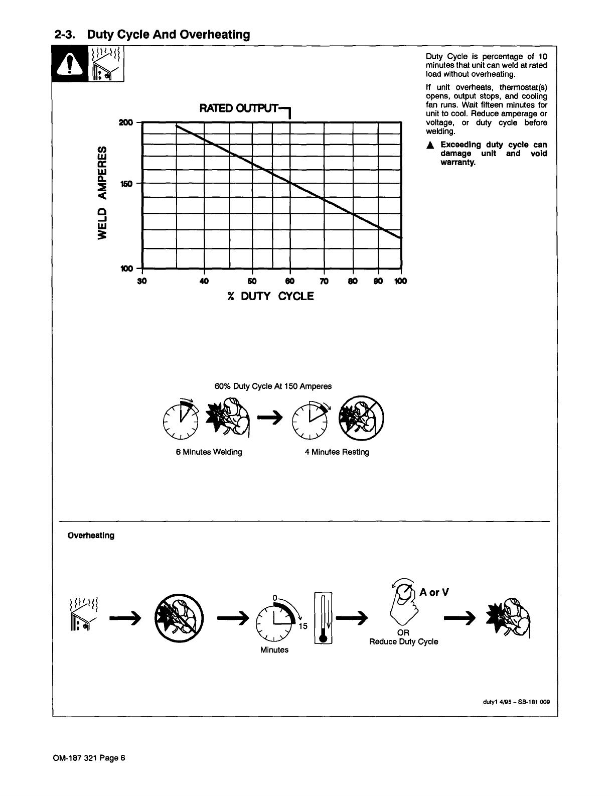
Duty
Cycle
is
percentage
of
10
minutes
that
unit
can
weld
at
rated
load
without
overheating.
If
unit
overheats,
thermostat(s)
opens,
output
stops,
and
cooling
fan
runs.
Wait
fifteen
minutes
for
unit
to
cool.
Reduce
amperage
or
voltage,
or
duty
cycle
before
welding.
A
Exceeding
duty
cycle
can
damage
unit
and
void
warranty.
dutyl
4/95
SB-181
009
200
150
100
30
40
50
60
DUTY
CYCLE
10
8000100
g
6
Minutes
Welding
4
Minutes
Resting
Overheating
Minutes
OR
Reduce
Duty
Cycle
OM-187
321
Page
6

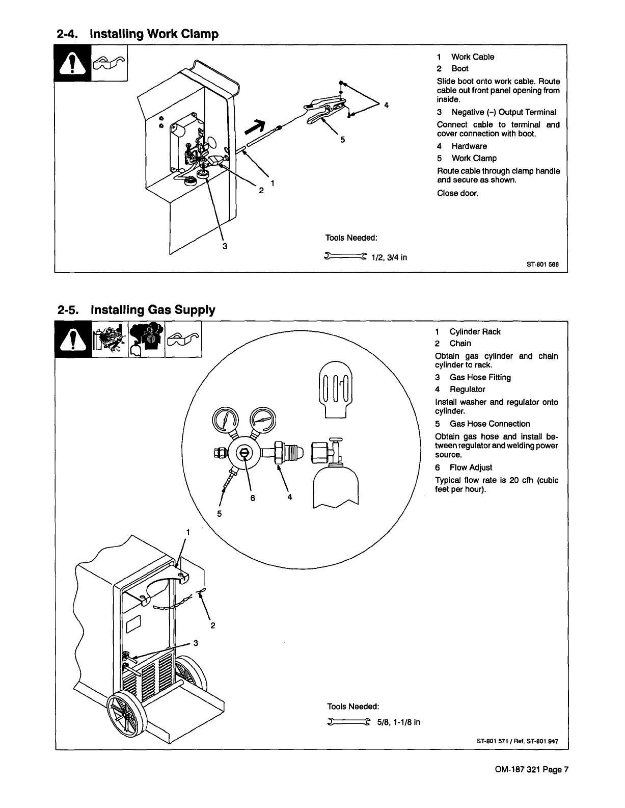
2-4.
Installing
Work
Clamp
2
1
Work
Cable
2
Boot
Slide
boot
onto
work
cable.
Route
cable
out
front
panel
opening
from
inside.
3
Negative
()
Output
Terminal
Connect
cable
to
terminal
and
5
cover
connection
with
boot.
4
Hardware
5
Work
Clamp
Route
cable
through
clamp
handle
and
secure
as
shown.
Close
door.
Tools
Needed:
~
1/23/4in
ST-8O1
588
2-5.
Installing
Gas
Supply
OM-187
321
Page
7

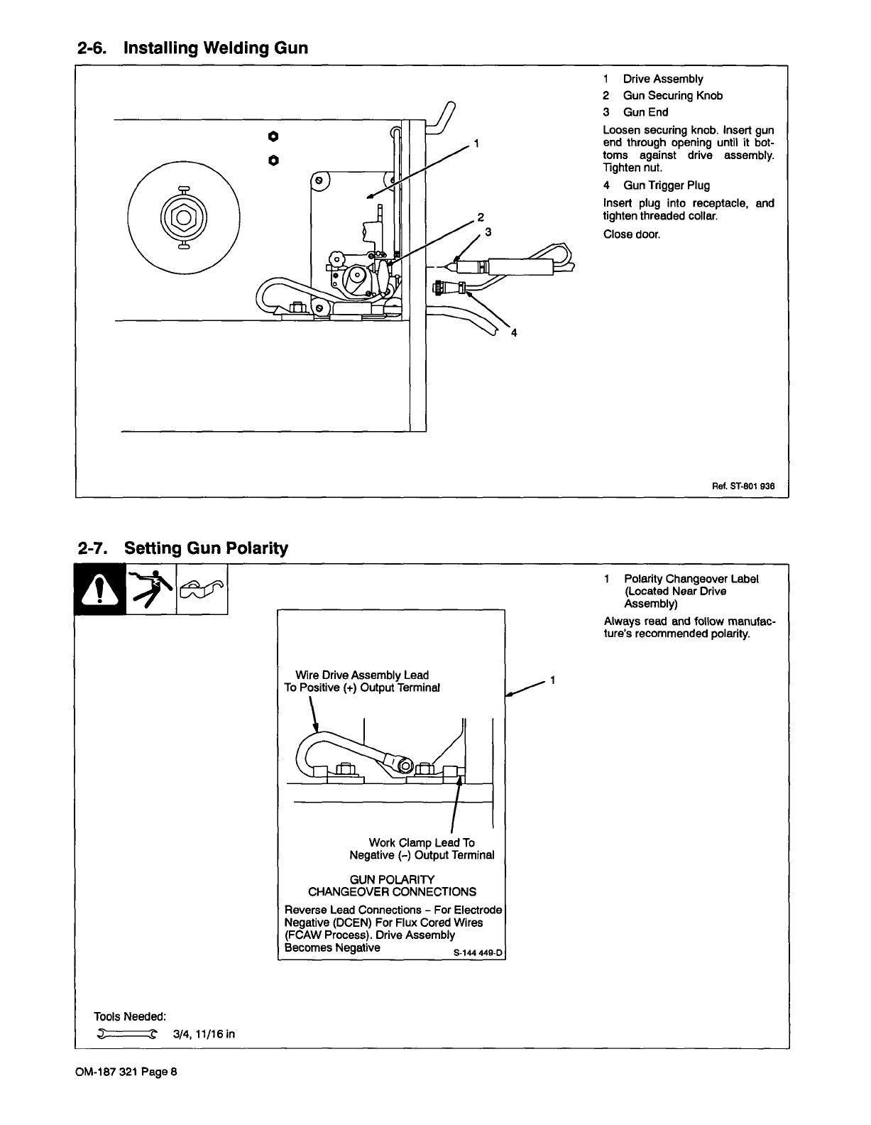
2-6.
Installing
Welding
Gun
2-7.
Setting
Gun
Polarity
Tools
Needed:
~
3/4,11/161n
1
Polarity
Changeover
Label
(Located
Near
Drive
Assembly)
Always
read
and
follow
manufac
tures
recommended
polarity.
2
3
1
Drive
Assembly
2
Gun
Securing
Knob
3
Gun
End
Loosen
securing
knob.
Insert
gun
end
through
opening
until
it
bot
toms
against
drive
assembly.
Tighten
nut.
4
Gun
Trigger
Plug
Insert
plug
into
receptacle,
and
tighten
threaded
collar.
Close
door.
Ref.
ST-801
936
4
Wire
Drive
Assembly
Lead
To
Positive
()
Output
Terminal
Work
Clamp
Lead
To
Negative
()
Output
Terminal
GUN
POLARITY
CHANGEOVER
CONNECTIONS
Reverse
Lead
Connections
For
Electrode
Negative
(DCEN)
For
Flux
Cored
Wires
(FCAW
Process).
Drive
Assembly
Becomes
Negative
~
~-D
OM-1
87
321
Page
8

/