Page is loading ...

PIG00-14673
Rechargeable In-Ground Fence
™
Operating Guide
Please read this entire guide before beginning

1-800-732-26772
Thank you for choosing PetSafe
®
Brand. You and your pet deserve a companionship that includes memorable moments and a shared
understanding. Our products provide you with the tools and technologies to successfully train your pet. If you have any questions about our
products or training your pet, please visit our website at www.petsafe.net or contact our Customer Care Center at 1-800-732-2677. To get
the most protection out of your warranty, please register your product within 30 days at www.petsafe.net. By registering and keeping your
receipt, you will enjoy the product’s full warranty and should you ever need to call the Customer Care Center, we will be able to help you
faster. Most importantly, we will never give or sell your valuable information to anyone. Complete warranty information is available online at
www.petsafe.net.
Hereinafter Radio Systems Corporation, Radio Systems PetSafe Europe Ltd., Radio Systems Australia Pty Ltd. and any other affiliate or brand of
Radio Systems Corporation may be referred to collectively as “We” or “Us.”
Important Safety Information
Explanation of attention words and symbols used in this guide
This is the safety alert symbol. It is used to alert you to potential personal injury hazards. Obey all safety messages that follow this
symbol to avoid possible injury or death.
WARNING indicates a hazardous situation which, if not avoided, could result in death or serious injury.
CAUTION, used with the safety alert symbol, indicates a hazardous situation which, if not avoided, could result in minor
or moderate injury.
CAUTION, used without the safety alert symbol, indicates a hazardous situation which, if not avoided, could result in
harm to your pet.
NOTICE is used to address practices not related to personal injury.
• Not for use with aggressive dogs. Do not use this product if your dog is prone to aggressive behavior. Aggressive
dogs can cause severe injury or death to their owners and others. If you are not sure that this product is right for your
dog, please talk to your veterinarian or a certified trainer.
• Underground cables can carry high voltage. Have all underground cables marked before you dig to bury your wire.
In most areas this is a free service. Avoid these cables when you dig.
• This device contains a Lithium-Ion (Li-Ion) battery; never incinerate, puncture, deform, short-circuit, or charge with an
inappropriate charger. Fire, explosion, property damage, or bodily harm may occur if this warning is not followed.
• The battery should be charged in areas with temperatures ranging from 32°F to 113°F / 0°C to 45°C. Recharging
the battery outside of this temperature range can cause the battery to overheat, explode or catch fire.
• Follow all safety instructions for your power tools. Be sure to always wear your safety goggles.
• Do not install, connect or remove your system during a lightning storm. If the storm is close enough for you to hear
thunder, it is close enough to create hazardous surges.
• Risk of electric shock. Use the fence transmitter and surge protector indoors in dry location only.
• Turn off the power to the outlet before you install or remove your surge protector.
• Risk of electrical shock or fire. Use the surge protector only with a duplex outlet with a center screw. Attach the unit
with the long screw supplied.

www.petsafe.net 3
• Risk of injury. Wire placed on top of the ground may be a trip hazard; use care in how you place your wires.
This PetSafe
®
Rechargeable In-Ground Fence
™
system is not a solid barrier. This system is designed to act as a deterrent
to remind pets, by static correction, to remain in the boundary established. It is important that you reinforce training with
your pet on a regular basis. Proper fit of the receiver collar is important. A receiver collar worn for too long or made
too tight on the pet’s neck may cause skin damage, ranging from redness to pressure ulcers; this condition is commonly
known as bed sores.
• Avoid leaving the receiver collar on the dog for more than 12 hours per day.
• When possible reposition the receiver collar on the pet’s neck every 1 to 2 hours.
• Check the fit to prevent excessive pressure; follow the instructions in this manual.
• When using a separate collar for a leash, do not put pressure on the receiver collar.
• Wash the dog’s neck area and the contact points of the receiver collar weekly with a damp cloth.
• Examine the contact area daily for signs of a rash or a sore.
• If a rash or sore is found, discontinue use of the receiver collar until the skin has healed.
• If the condition persists beyond 48 hours, see your veterinarian.
• For additional information on bed sores and pressure necrosis, please visit our website.
These steps will help keep your pet secure and comfortable. Millions of pets are comfortable while they wear stainless
steel contact points. Some pets are sensitive to contact pressure. You may find after some time that your pet is very
tolerant of the receiver collar. If so, you may relax some of these precautions. It is important to continue daily checks of
the contact area. If redness or sores are found, discontinue use until the skin has fully healed.
You may need to trim the hair in the area of the contact points. Never shave the dog’s neck; this may lead to a rash
or infection.
• The receiver collar should not be on your dog when the system is tested. Your pet may receive an
unintended correction.
• The boundary width of the system must be tested whenever an adjustment is made to the pet area to prevent
unintended corrections to your pet.
• If you use a collar and leash for training, be sure the extra collar does not put pressure on the contact points.
• Always remove your dog’s receiver collar before performing any transmitter testing.
• If possible, DO NOT use an AC circuit protected with a Ground Fault Circuit Interrupter (GFCI) or Residual Current
Device (RCD). In rare cases, nearby lightning strikes may cause the GFCI or RCD to trip. Without power your dog
may be vulnerable to escape. You will have to reset the GFCI or RCD to restore power to the system.
Do not install the surge protector if there is not at least 30 ft. (10 m) or more of wire between the electrical outlet and electrical
service panel.

1-800-732-26774
• Plug the surge protector into a grounded (3-prong) outlet that is within 5 ft. of the fence transmitter. ALWAYS use a
grounded (3-prong) outlet to ensure maximum protection.
• Do not remove the ground prong from the surge protector plug. Do not use a 3-prong plug to 2-prong outlet
converter. Doing so will make the surge protector ineffective against surges or spikes.
• You should expect hundreds of recharge cycles from your battery. However, do not charge your receiver collar every
night. Charging too often can reduce battery life. Charge your receiver collar when the receiver indicator light blinks red.
• Use care when mowing or trimming your grass not to cut the loop wire.
• Verify that the boundary loop and transmitter wires connect to the proper surge protector terminals. Reversed
connections will result in an increased risk of surge related damage.
• For added protection, when unused for long periods of time or prior to thunderstorms, unplug from the wall outlet and
disconnect the loop boundary wires. This will prevent damage to the transmitter due to surges.
• To prevent an unintended correction, after the boundary flags have been placed, be sure to set the static correction
on the receiver collar back to level 1, which is tone only.

www.petsafe.net 5
Table of Contents
Components ........................................................................................................................................................................................................................ 6
Other Items You May Need ...........................................................................................................................................................................................6
How the System Works ....................................................................................................................................................................................................7
Key Definitions ...................................................................................................................................................................................................................7
Operating Guide ........................................................................................................................................................................................................ 8
Step 1: Have Your Utilities Marked .........................................................................................................................................................................8
Step 2: Charge the Receiver Collar ........................................................................................................................................................................8
Step 3: Install the Surge Protector and Transmitter ...............................................................................................................................................8
Step 4: Design Your Boundary Zone ................................................................................................................................................................... 10
Step 5: Position, Twist and Splice the Boundary Wire ......................................................................................................................................13
Step 6: Connect the Wires ..................................................................................................................................................................................... 14
Step 7: Prepare the Receiver Collar ..................................................................................................................................................................... 16
Step 8: Set the Boundary Width and Test the Receiver Collar ...................................................................................................................... 18
Step 9: Bury the Boundary Wire ...........................................................................................................................................................................20
Step 10: Place the Boundary Flags .......................................................................................................................................................................21
Step 11: Fit the Receiver Collar .............................................................................................................................................................................. 22
Training Guide .......................................................................................................................................................................................................... 24
Day 1—Tone-only Training for Boundary Awareness ...................................................................................................................................... 25
Days 2 Through 4—Boundary Awareness with Static Correction ................................................................................................................ 26
Days 5 Through 8—Distraction Phase .................................................................................................................................................................. 26
Days 9 Through 14—Unleashed Supervision .................................................................................................................................................... 27
Days 15 Through 30—Pet Monitoring ................................................................................................................................................................. 28
Taking Your Pet Out of the Pet Area ............................................................................................................................................................................ 28
Accessories ...................................................................................................................................................................................................................... 28
System Test........................................................................................................................................................................................................................ 29
Wire Break Location Test .............................................................................................................................................................................................. 30
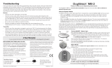
Troubleshooting ....................................................................................................................................................................................................... 32
Terms of Use and Limitation of Liability ..................................................................................................................................................................... 33
Compliance ...................................................................................................................................................................................................................... 34
Customer Care International ........................................................................................................................................................................................ 34
Battery Disposal ..............................................................................................................................................................................................................34
Warranty ......................................................................................................................................................................................................................35

1-800-732-26776
Components
Other Items You May Need
• Additional wire and flags (Part #PIG00-13769)
• Additional wire nuts and gel-filled splice capsules
• Drill and mounting hardware
• Tape measure
• Small Phillips screwdriver
• Pliers
• Staple gun
• Scissors
• Lighter
• Shovel or lawn edger
• Wire stripping pliers
• Waterproofing compound (e.g. silicone caulk)
• PVC pipe or water hose
• Circular saw with masonry blade
• Non-metallic collar and leash
Setup and training help: www.petsafe.net
BATTERY 6V
RFA-67
PIG00-14673
Rechargeable In-Ground Fence
™
Operating Guide
Please read this entire guide before beginning
Test Light
Tool
Gel-filled Capsules
Receiver Collar with
Short Contact Points
Fence Transmitter
Operating and
Training Guide
(50)
Boundary Flags
Power
Adapter
Boundary Wire
Wire Nuts
Mounting
Bracket
Long
Contact Points
Receiver
Charger
Surge Protector
(USA & Canada Only)

www.petsafe.net 7
How the System Works
A radio signal travels from the fence transmitter through a buried wire, marking the boundaries you wish to set for your dog. Your dog wears
a receiver collar that detects the signal at the boundary. As your dog approaches the boundary, the receiver issues a warning tone. If he
proceeds further, he receives a safe but startling static correction. While harmless, the correction will persuade him to stay in the containment
area you have established. Boundary flags are a temporary visual aid for your pet; remove them after training. This PetSafe
®
Rechargeable
In-Ground Fence
™
system has been proven safe, comfortable and effective for pets over 5 pounds.
Key Definitions
Fence Transmitter: Transmits the radio signal through the boundary wire.
Pet Area: The area within the warning zone where your pet can roam freely.
Warning Zone: The outer edge of the pet area where your pet’s receiver collar begins to
beep, warning him not to go into the static correction zone.
Static Correction Zone: The zone beyond the warning zone where your pet’s receiver collar
will emit a static correction, signaling him to return to the pet area.
Boundary Width: The combination of the warning zone and the static correction zone.
Surge Protector: Installed with the fence transmitter to protect it from lightning strikes and
power surges (USA and Canada only).
Receiver Collar: Receives the radio signal from the boundary wire.
Mode Button: Turns the receiver on/off and adjusts the level of static correction that your pet
receives outside the pet area.
Receiver Indicator Light: Indicates the level of correction at which the receiver collar is set.
This light also indicates battery status.
Contact Points: Delivers the safe static correction when your pet moves into the static
correction zone.
Receiver Charger: Charges the batteries inside the receiver collar.
Receiver Charge Jack: The connection point for charging the
receiver battery.
Power Jack: Where the power adapter plugs into the fence transmitter.
Boundary Control Switch: The switch located on the fence transmitter
to adjust according to the length of boundary wire used.
Boundary Wire Terminals: Where the boundary wires connect to the
fence transmitter in order to complete a continuous loop.
Loop Indicator Light: Indicates that the boundary wire makes a
complete loop, enabling the signal to be transmitted.
Boundary Width Control: Adjusts the width of the warning and static
correction zones.
Note: Adjusting the knob does not change the level of static correction
on the receiver collar.
Fence
Transmitter
Static
Correction
Zone
Warning
Zone
Static
Correction
Zone
Warning
Zone
Pet
Area
Boundary
Width
Surge
Protector
with Power
Adapter
Receiver Charge Jack
Contact Points
Mode Button
Receiver
Indicator
Light
Receiver Collar Fence Transmitter
Boundary Control Switch
Boundary Wire
Terminals
Loop Indicator Light
Power Light
Power
Jack
Boundary Width
Control

1-800-732-26778
Operating Guide
Step 1: Have Your Utilities Marked
1. Call your utility company to have your utility lines marked. If you
have neighbors using an in-ground pet containment system, you
will want to ask them where the boundary is located. Trust us, you
really do not want to skip this step.
2. Make a plan for how you will work around any large metal
objects (like sheds) or wires. You can cross utility lines but only at
90° angles (1A).
Note: Large metal objects and wires can amplify and/or modulate
radio signals in unpredictable ways.
Underground cables can carry high voltage. Have all underground cables marked before you dig to bury your wire. In
most areas, this is a free service. Avoid these cables when you dig.
Step 2: Charge the Receiver Collar
The receiver charger has two jacks that allow you to charge two receiver collars at the same time.
To charge the receiver collar, lift the rubber plug to allow access to the charge jack (2A). The
rubber plug needs to remain attached to the receiver collar. Plug one end of the charger into the
outlet and the other into the receiver collar. The jack and charger are keyed to fit one way. Do not
force it in backwards. The collar light is red while charging and green when fully charged. A built
in safety circuit prevents the receiver collar from overcharging. The first charge will take about 2 or 3
hours. Each charge can last up to 3 months depending on the frequency of use.
• The rechargeable Lithium Ion (Li-Ion) battery is not memory sensitive, does not require depletion before charging, and cannot be
over charged.
• The battery comes partially charged from the factory, but will require a full charge before first use.
• When storing the unit for long periods, remember to regularly give the battery a full charge. This should be done once every 3 to 4 months.
• This device contains a Lithium-Ion (Li-Ion) battery. Never incinerate, puncture, deform, short-circuit, or charge with an
inappropriate charger. Fire, explosion, property damage, or bodily harm may occur if this warning is not followed.
• The battery should be charged in areas with temperatures ranging from 32°F to 113°F / 0°C to 45°C. Recharging the
battery outside of this temperature range can cause the battery to overheat, explode or catch fire.
• You should expect hundreds of recharge cycles from your battery. However, do not charge your receiver collar every
night. Frequent charging can have a negative effect on the battery. We recommend that the receiver collar be used
until the receiver indicator light blinks red.
Step 3: Install the Surge Protector and Transmitter
Lightning strikes that occur even several miles away from your installation can create power surges or spikes which may damage an
unprotected system. The surge protector is included to safeguard your Rechargeable In-Ground Fence
™
system against surges or spikes that can
reach it via your AC power connection and/or boundary wire. Find a place to install the surge protector and transmitter. There are a few things
to consider when choosing an outlet for your surge protector and transmitter:
90°
10’
Buried Cable
Boundary Wire
10’
1A
2A

www.petsafe.net 9
• We recommend using an outlet at least 30 ft. from the breaker box.
• Both the surge protector and transmitter should be indoors, in a dry, ventilated and protected area (3A, 3B).
• You will need to run wire from the transmitter to the boundary wire, so it must be near window or a wall that you can drill through (3A). The
wire should not be pinched or cross any utility lines.
• The temperatures in that location should not fall below -10°F or -23°C.
• Both the surge protector and transmitter should be at least 3 ft. from large metal objects or appliances (3C). These items may interfere with
the signal consistency.
• In case your system sounds an alarm, place it where you will be able to hear and access it.
To mount the fence transmitter, screw the mounting bracket onto a stationary surface such as a wall, and slide the fence transmitter onto the
bracket. Once you have mounted the fence transmitter, the boundary wire must exit the building. This can be accomplished via a window or
through a hole drilled through the wall. Ensure the drill path is clear of any utilities. Make sure the boundary wire is not cut off or pinched by a
window, door, or garage door, as this can damage it over time.
To prevent fires and electrical hazards, install the fence transmitter in buildings that are in accordance with state and local electrical codes.
• Do not install, connect or remove your system during a lightning storm. If the storm is close enough for you to hear
thunder, it is close enough to create hazardous surges.
• Risk of electric shock. Use the fence transmitter and surge protector indoors in dry location only.
• Turn off power to the outlet before you install or remove your surge protector.
• Risk of electric shock or fire. Use surge protector only with a duplex outlet with center screw.
• Do not install the surge protector if there is not at least 30 ft. (10 m) or more of wire between the electrical outlet
and electrical service panel.
• If possible, DO NOT use an AC circuit protected with a GFCI (ground fault circuit interrupter). Both the surge
protector and the fence system will function. However, in rare cases, nearby lightning may cause the GFCI to trip.
Without power, your pet may escape. You will have to reset the GFCI to restore power to the system.
• Plug the surge protector into a grounded (3-prong) outlet within 5 ft. of the fence transmitter. ALWAYS use a
grounded (3-prong) outlet to ensure protection.
• Do not remove the ground prong from the surge protector plug. Do not use a 3-prong plug to 2-prong outlet
converter. Doing so will make the surge protector ineffective against surges or spikes.
• For added protection, when unused for long periods of time or prior to thunderstorms, unplug from the wall outlet
and disconnect the loop boundary wires. This will prevent damage to the transmitter due to surges.
3B
3 ft.
3 ft.
3C
3A

1-800-732-267710
Step 4: Design Your Boundary Zone
Basic Planning Tips
• Always design your layout, position the boundary wire and test the system as outlined in this guide before burying the boundary wire. You
do not want to find out after burying the wire that there is a problem with your layout or a loose connection somewhere.
• Sample layouts are provided in this section, and a grid for designing your layout is provided on the back of this guide.
• The boundary wire must start at the fence transmitter and make a continuous loop back (4A).
• Always use gradual turns at the corners with a minimum of 3 ft. radius to produce a more consistent boundary (4B). Do not use sharp turns;
this will cause gaps in your boundary.
• Create areas in your yard that allow your pet to safely cross over the boundary wire without static correction by twisting the boundary wires
together 10 to 12 times per ft. (4C). This cancels the signal and allows your pet to safely cross over that area.
• To properly contain your pet, we recommend setting a boundary width for the warning and static correction zones to approximately
12–20 ft. (6 to 10 ft. on each side of the wire).
• Avoid making passageways too narrow for your pet to move about freely (e.g., along the sides of a house).
• The receiver collar can be activated inside the house if the boundary wire runs along the outside wall of the house. If this occurs,
remove your pet’s receiver collar before bringing him inside, decrease the range using the boundary width control knob or consider an
alternate layout.
4A
4B

www.petsafe.net 11
Single or Double Loop Layout
The containment area can be created by using either a single boundary wire that is placed around the entire property (4C) or by doubling the
boundary wire along the same path (4E).
Single Loop Boundary
• To create a containment area for the entire property
• For exclusion areas around gardens, landscaping or pools
With a single loop layout, the boundary wire starts at the fence transmitter, advances out to the yard, continues all the way around the
perimeter of the property and connects back to the fence transmitter. This forms a boundary zone with a single wire.
Sample 1: Perimeter Loop (4C) The perimeter loop is the most common layout. This
will allow your pet to freely and safely roam your entire property. It can also protect
gardens, pools and landscaping.
Sample 2: Full Perimeter Loop Using Existing Fence (4D) This layout allows you
to include your existing fence as part of your layout and keep your pet from jumping out
or digging under your existing fence. This layout also greatly reduces the installation time
since most of the wire will not need to be buried.
Run the wire from the fence transmitter to point A, then to point B and so on (B to C to D
to E) all the way around the entire property until back to point A again. The wires from
point A will then need to be twisted and connected back to the fence transmitter inside
your home.
Wire
Splices
Place
Transmitter
Inside
Pets Can
Safely Cross
Twisted Wires
Pets Can
Safely Cross
Twisted Wires
10 Twists/ft.
4C
D
E
A
C
B
4D

1-800-732-267712
Double Loop Boundary
• To section off only one boundary area or one section of your yard (e.g., front yard
only, or waterfront property)
• The 2 parallel sections of the double boundary wire must be separated by a
minimum of approximately 5 ft. from each other in order to avoid canceling out
the signal as well as provide an adequate boundary width (4E)
• A double loop layout requires twice as much wire as a single loop layout because it
doubles back along the same path
With a double loop layout, the boundary wire starts at the fence transmitter, advances
out to the yard and continues to form a boundary zone in one section of your property
(e.g., front yard only). Then the wire makes a U-turn back along the same path and
connects back to the fence transmitter. This forms a boundary zone with a double wire.
Sample 3 (4E): Front Yard or Back Yard Only (Double Loop)
From the fence transmitter, run the wire to point A, then to point B and so on (B to C to
D to E to F). Next, make a U-turn and follow your path all the way back to point G,
keeping the wire separated by at least 5 ft. When you get back to the house (G), make
a sharp turn along the side of the house back to point A. Finally, twist the wires from
point A and connect them back to the fence transmitter.
Sample 4 (4F): Front Boundary Only (Double Loop)
From the fence transmitter, run the wire to point A, then to point B. Make a U-turn and
follow your path back to point A, keeping the wire separated by at least 5 ft. Then twist
the wires from point A and connect them back to the fence transmitter.
Sample 5 (4G): Waterfront Property (Double Loop)
From the fence transmitter, run the wire to point A, then to point B. Make a U-turn and
follow your path to C, then to D, then to E. Next, make another U-turn and follow the
same path all the way back to point A, keeping the wire separated by at least 5 ft.
Finally, twist the wires from point A and connect them back to the fence transmitter.
Sample 6 (4H): Wire Loop Attached to Existing Fence (Double Loop)
This layout allows you to include your existing fence as part of your layout and keep
your pet from jumping out or digging under your existing fence. It reduces the amount of
wire which will need to be buried. From the fence transmitter run the wire to point A, then
to point B and so on (B to C to D to E to F). Next, make a U-turn and follow your path
all the way back to point A, keeping the wire separated by at least 5 ft. Finally, twist the
wires from point A back to the fence transmitter.
A
C
D
E
B
5’
A
B
5’
E
F
B
Place Transmitter Inside
A
A
G
G
D
C
5’
A
C
D
E
F
B
5’
4E
4F
4G
4H

www.petsafe.net 13
Step 5: Position, Twist and Splice the Boundary Wire
Once you have designed your layout, the next step is to position the wire along your property. Hold off on burying the wire until you have
tested the system first.
1. Start with one end of the wire at the surge protector, but do not plug it in yet. Run the wire outdoors all the way around your planned
perimeter and back to the surge protector.
2. You will need to twist the 2 wires together for the area running from the transmitter inside your home out to the yard so that your pet can
cross this section without a correction (5A). Twisting both ends of the wire together 10–12 times per ft. cancels the signal. Keep in mind
that crossover areas will only work when set up within the containment area. Straight crossover breaks along the perimeter, such as across
driveways (5B), cannot be created and the signal will not be canceled.
Quick tip: The fastest way to twist 2 wires is to cut 2 pieces a little longer than the length you need, twist them and then “splice” in that section.
Anchor one end of the 2 wires to something secure (or have a partner hold them), and insert the other end into a power drill. Pull the wire taut.
Then use the drill to twist the wire quickly. Go slowly. Follow the splicing guide below to learn how to reconnect this twisted portion back to the
main boundary wire.
Splicing Guide
Although not required, it is recommended that you cut and splice the wire between each twisted section. Your Rechargeable In-Ground Fence
™
system comes with 2 gel-filled splice capsules to ensure that your splices are waterproof. You can give us a call if you would like to purchase more
splice capsules.
a. Strip approximately
3
⁄8 in. of insulation off the ends of the wires to be spliced (5C).
b. Insert the stripped ends into the wire nut and twist the wire nut around the wires. Make sure there is no copper exposed beyond the end
of the wire nut.
c. Tie a knot 3 to 4 in. from the wire nut (5D). Ensure that the wire nut is secure on the wire splice.
d. Once you have securely spliced the wires together, open the lid of the gel-filled splice capsule and insert the wire nut as deeply as
possible into the waterproof gel inside the capsule (5E).
e. Snap the lid of the capsule shut (5F).
5B
5A
1
2
5C 5D 5E 5F

1-800-732-267714
Additional Boundary Wire
Extra spools of boundary wire can be purchased in lengths of
500 ft. per spool where you purchased the kit or through the
Customer Care Center.
Note: When adding boundary wire, it must act as a continuous loop.
The table on the right indicates the approximate length of boundary
wire needed for a square, single loop layout. The length will vary due
to the amount of twisted wire and the layout used.
Step 6: Connect the Wires
Now that the boundary wire has been positioned and spliced, the next
step is to connect the wire from inside to the surge protector, and then to
the transmitter.
1. Strip
3
⁄8 in. of insulation from the 2 ends of the boundary wires in
order to connect them to the surge protector (6A).
2. Insert the stripped ends into the 2 left red connector holes on the
bottom of the surge protector labeled “LOOP” (6B). Make sure the
copper ends do not touch each other at the terminals.
3. Next, connect the surge protector to the fence transmitter with 2
twisted wires. Measure and cut 2 lengths of wire, then strip
3
⁄8 in. of
insulation at both ends from each. Twist the 2 lengths together, with
at least 10–12 twists per ft., so the wires will not send out a signal.
4. Insert the 2 ends of the wires into the 2 black connectors at the
bottom of the surge protector labeled “TRANSMITTER.”
5. Next, insert the opposite ends of the twisted wire into the 2 red tabs
on the fence transmitter.
6. Turn the boundary width control knob to 10. This will set the
boundary width at the maximum width.
7. Plug the fence transmitter adapter into the outlet on the surge
protector. You are now all connected (6C).
8. The power light and loop indicator light should come on. If this does
not happen, check out our troubleshooting section, watch one of
our instructional videos or give us a call.
Boundary
Wire
Transmitter Wires
6C
LOOP TRANSMITTER
BOUCLE ÉMETTEUR
Push Tab
Down to
Insert Wire
6B6A
Acres Feet of Wire Needed Number of Spools Needed
1
⁄4 415 1
1
⁄3 480 1
1
⁄2 590 2
1 835 2
2 118 0 3
5 1870 4
10 2800 6
25 4500 9

www.petsafe.net 15
Verify that the boundary loop and transmitter wires are connected to the proper surge protector terminals. Reversed
connections will result in an increased risk of surge-related damage.
For added protection, when unused for long periods of time or prior to thunderstorms, unplug from the wall outlet and
disconnect the loop boundary wires. This will prevent damage to the transmitter due to surges.
Transmitter Setup
(Australia and New Zealand)
1. Run the boundary wire through a window, under a door, through a crawl space vent or any other appropriate available access. You can
also drill a hole through your wall.
2. Strip
3
⁄
8
inch of insulation from the ends of the boundary wire.
3. Press the red tabs on the fence transmitter and insert the twisted wire into the boundary wire terminals. Make sure wires do not touch each
other at the terminals.
4. Turn the boundary width control knob to 10. This will set the boundary width at the maximum width.
5. Plug the power adapter into the power jack and AC power outlet.
6. The power light and loop indicator light should come on. If this does not happen, check out our troubleshooting section, watch one of our
instructional videos or give us a call.
• Do not install, connect, or remove your system during a lightning storm. If the storm is close enough for you to hear
thunder, it is close enough to create hazardous surges.
• Risk of electric shock. Use the fence transmitter indoors in dry location only.
If possible, DO NOT use an AC circuit protected with a Ground Fault Circuit Interrupter (GFCI) or Residual Current
Device (RCD). In rare cases, nearby lightning strikes may cause the GFCI or RCD to trip. Without power your dog
may be vulnerable to escape. You will have to reset the GFCI or RCD to restore power to the system.
For added protection, when unused for long periods of time or prior to thunderstorms, unplug from the wall outlet and
disconnect the loop boundary wires. This will prevent damage to the transmitter due to surges.

1-800-732-267716
Step 7: Prepare the Receiver Collar
In order to test the system you will need to use the receiver collar. Your receiver collar comes installed with
short contact points. If your pet has long or thick hair, use the long contact points instead. Tighten or switch
the contact points by using the contact point wrench (7A).
Turn the Receiver Collar On
To turn on the receiver collar, press and hold the mode button continuously for 5 seconds (7B). The
receiver indicator light will turn on for 5 seconds to indicate battery status (green, yellow or red), followed
by a series of red flashes which represent the static correction level.
Turn the Receiver Collar Off
To turn off the receiver collar, press and hold the mode button continuously for 5 seconds (7B). The red
receiver indicator light will be on during this time. The red receiver indicator light will then turn off and
all receiver indicator lights will stay off indicating that the unit is turned off. To extend the time between
charging the receiver collar, consider turning off the receiver collar when it is not in use.
Receiver Collar Status Indicators
The receiver collar status indicator light, along with the receiver collar alarm tone, are used to determine
the battery status and the correction type. Refer to the receiver collar status indicator table below to
understand the status lights and tones for the receiver collar.
During normal operation, the receiver collar indicator light will flash every 4–5 seconds to indicate the battery status as shown in the following table.
Receiver Collar Status Indicator Table
Status Light Alarm Tone Condition
While Plugged into the Receiver Charger
Solid red No tone Charge in progress
Solid green No tone Charge complete
No light – Charge failure, contact Customer Care Center
After Removing from the Receiver Charger
Continuous green, yellow or red
(5 seconds duration)
No tone
Battery charge indication. Occurs immediately after
unplugging the charger from the receiver collar
Operating Battery Status
Slow blinking green
(every 4–5 seconds) No tone Collar battery charge 100%–60%
Slow blinking yellow
(every 4–5 seconds) No tone Collar battery charge 60%–20%
Slow blinking red
(every 4–5 seconds) No tone Collar battery charge 20% or less, charge immediately
Receiver Activation Status
Fast pulsating green
(3 flashes per second) Warning tone Warning tone
Fast pulsating red
(3 flashes per second) Tone for duration of static correction Static correction being delivered up to 15 seconds
Continuous green
(10 seconds) No tone Over Correction Protection; collar locked for 10 seconds
Mode Button/
Receiver Indicator Light
7A
7B

www.petsafe.net 17
Set the Static Correction Level
The static correction levels increase in strength from 2 to 5, with level 1 being tone only (no correction), and level 5 being the maximum setting.
Refer to the table below to choose the static correction that best fits your pet.
1. Press and hold the mode button (7B) until the receiver collar illuminates a red light.
2. The receiver collar will then emit a series of red flashes representing the static correction level (e.g., 4 red flashes means level 4). You must
count the number of red flashes to determine the level setting.
3. Increase the static correction level by pressing and holding the mode button for 1 second after each series of flashes.
Note: Once you count 5 red flashes you are at level 5, and an additional hold will cycle the receiver collar back to level 1, which is tone only.
Static Correction Level Table
Indicator Light Static Correction Level Static Correction
1 1 red flash None—tone only
2 2 red flashes Low
3 3 red flashes Medium
4 4 red flashes Medium-high
5 5 red flashes High
Anti-Linger Prevention
The Anti-Linger Prevention feature keeps your dog from staying in the warning zone for long periods of time and draining the receiver collar
battery. Your dog will hear a warning tone when he reaches the warning zone. If your dog does not return to the pet area after 2 seconds, he
will receive a continuous static correction until he returns to the pet area.
Run Through Prevention
This system includes a unique Run Through Prevention feature so that your dog cannot “run through” the pet area without receiving an increased
level of static correction. The receiver collar automatically increases the static correction when your dog continues more than 20% of the way
through the pet fencing boundary width. For example, if the signal is detected 10 ft. from the wire and your dog enters the static correction
zone, this feature is activated when he is approximately 8 ft. from the boundary wire. Your dog will then receive a static correction that is at
an increased level corresponding to the static correction level setting on the receiver collar. The receiver collar is equipped to automatically
increase the level of static correction the longer your pet remains in the static correction zone if the collar is set at level 2 or above. The Run
Through Prevention sound is an intermittent tone.
Over Correction Protection
In the unlikely event that your pet “freezes” in the static correction zone, this feature limits the static correction duration to a maximum of 15
seconds. After 15 seconds, the static correction will stop and the green indicator light will stay on for 10 seconds. The receiver collar remains
locked out until your pet leaves the static correction zone.

1-800-732-267718
Step 8: Set the Boundary Width and Test the Receiver Collar
With the boundary wire in place and properly connected, and the receiver collar fully charged, it is time to set the boundary width and test
the system.
The receiver collar should not be on your dog when the system is tested.
Note: The receiver collar is waterproof, which can make the tone hard to hear.
The flashing test light, when held to the contact points, indicates that the receiver collar is delivering static correction. To best utilize the
automatic Run Through Prevention feature, the containment boundary width should extend at least 6 to 10 ft. on each side of the boundary wire
(total boundary width of 12 to 20 ft.).
1. Apply power to the fence transmitter with the supplied power adapter.
2. Set the boundary width control switch (located on the side of the fence
transmitter)
(8A)
to setting A, B, or C, based on the total length of boundary
wire used.
Setting B is used for most properties.
Refer to the table to the right for
the proper setting for your yard.
3. The boundary width is adjusted by using the transmitter’s boundary width
control knob (8B). Turn the knob counterclockwise until the alarm sounds and the loop indicator light is no longer lit. Turn the knob clockwise
and increase by 2 numbers. The alarm should turn off and the light should turn on.
The receiver collar should not be on your dog when the system is tested. Your pet may receive an unintended correction.
4. To identify the warning and static correction zones make sure the static correction on the receiver collar is set at level 5 (see Step 7).
5. Test the boundary width of the system by selecting a section of straight boundary wire that is at least 50 ft. long. Start inside the center of the
pet area.
6. Place the test light tool contacts against the receiver collar contact points (8C). Hold the receiver collar at your dog’s neck height with the
contact points pointing up. Slowly walk toward the boundary wire until you hear the warning tone (8D). When you hear the warning tone,
you have identified the boundary width distance (static correction zone). Two seconds after the warning tone, the test light will begin to
flash. This flashing light can aid you in identifying the boundary width if you have difficulty hearing the tone.
Setting Amount of Wire Used
A Greater than 2400 ft.
B Up to 1300 ft.
C 1300 to 2400 ft.
Boundary Width
Control Knob
Boundary
Wire
8C
8D
C
B
A
C
B
A
8A
8B

www.petsafe.net 19
7. To prevent the receiver collar from going into Over Correction Protection mode, walk back into the pet area until the toning stops.
If the
receiver collar does not tone at the desired range, adjust the boundary width control knob to obtain the desired range. Turning the boundary
width control knob clockwise increases the boundary width while turning it counterclockwise decreases
it (8E). Repeat this activity as
needed until the receiver collar tones between 6 to 10 ft. from the boundary wire. If using a double loop layout, you may need to increase
the separation of the boundary wire and/or increase the size of the boundary width to achieve the desired range.
8. Test the boundary width in a number of different locations around the pet area until you are satisfied that the system is functioning properly.
9. Next, walk all around the pet area (8F) to ensure there are no areas where the receiver collar may activate from signals coupled onto
buried wires or cables. Test the collar in and around the inside of the house as well. As mentioned, cable and wires from cable TV, electrical
or telephone lines may conduct pet fencing signals inside and outside the house that can activate the dog’s collar accidentally. While rare,
if this occurs, your boundary wire is probably too close to these outside lines and should be moved or modified as shown in figure 1A.
10. To test the Run Through Prevention feature, walk towards the boundary wire. The receiver collar should tone and the test light should flash
brighter as you enter the run through area (8G). If you are satisfied that your system is functioning properly, you are ready to start burying
the boundary wire. If the receiver collar did not tone or the test light did not flash, see the troubleshooting section.
Pet Area
Boundary
Wire
8E
5
2 8
4
10
3
9
1
7
0
6
5
2 8
4
10
3
9
1
7
0
6
8G8F

1-800-732-267720
Step 9: Bury the Boundary Wire
• Underground cables can carry high voltage. Have all underground cables marked before you dig to bury your
wire. In most areas, this is a free service. Avoid these cables when you dig.
• Before you begin installing the boundary wire, turn the fence transmitter off and unplug the adapter from the
surge protector.
Burying the boundary wire is recommended to protect it and prevent
disabling the system.
1. Cut a trench 1–3 inches deep along your planned boundary. It only
needs to be as wide as the wire.
Quick Tip: We have tried lots of tools. Lawn trenchers, which you can often
rent from a local hardware store, work great and make for a quick job. You
can also use a flat shovel, like a trenching shovel.
2. Place the boundary wire into the trench maintaining some slack to allow it
to expand and contract with temperature variations.
3. Use a blunt tool such as a wooden paint stick to push the boundary wire
into the trench. Be careful not to damage the boundary wire insulation.
Utilizing an Existing Fence
The boundary wire can be attached to a chain link fence, split rail fence or
a wooden privacy fence. The boundary wire can be attached as high as
needed. However, make sure the boundary width is set at a high enough
range for your pet to receive the signal. If using a double loop with an
existing fence at least 5 ft. tall, run the boundary wire on top of the fence and
return it on the bottom of the fence to get the 5 ft. separation needed.
• Chain Link Fence (9A):
Weave the boundary wire through the links or use plastic quick ties.
• Wooden Split Rail or Privacy Fence (9A):
Use staples to attach the boundary wire. Avoid puncturing the insulation
of the boundary wire.
• Double Loop with an Existing Fence:
Run the boundary wire on top of the fence and return it on the bottom of
the fence to get the 5 ft. separation needed.
• Gate (Single Loop) (9B):
Bury the boundary wire in the ground across the gate opening.
Note: The signal is still active across the gate. Your pet cannot pass
through an open gate.
• Gate (Double Loop) (9B):
Bury both boundary wires across the gate opening while keeping them
5 ft. apart.
Single Loop
Double Loop
5' 5'
9B
Weave Wire Into Fence
Staple Wire Into Fence
9A
/