Page is loading ...

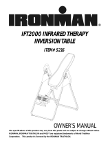
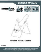
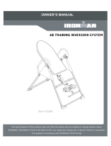
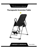
INVERSION TABLE
with Memory Foam
ITEM NO: 75164
OWNER’S MANUAL
IMPORTANT: Read all instructions carefully before using this product. Retain this
owner’s manual for future reference.
The specifications of this product may vary from this photo and are subject to change without
prior notice.

1
TABLE OF CONTENTS
WARRANTY -------------------------------------------------------------------------------- 2
IMPORTANT SAFETY INSTRUCTIONS ------------------------------------------- 3
EXPLODED VIEW ----------------------------------------------------------------------- 5
PARTS LIST ------------------------------------------------------------------------------- 6
HARDWARE AND TOOLS PACK ---------------------------------------------------- 8
ASSEMBLY INSTRUCTIONS --------------------------------------------------------- 9
SAFETY OPERATING INSTRUCTIONS ------------------------------------------- 15
HOW TO USE ----------------------------------------------------------------------------- 16
QUICK RELEASE ANKLE LOCK ----------------------------------------------------- 18
OPERATION ------------------------------------------------------------------------------- 19
WARM UP AND COOL DOWN ROUTINE ----------------------------------------- 21

2
ONE YEAR LIMITED WARRANTY
LifeGear Inc. warrants to the original purchaser that this product is free from defects in
material and workmanship when used for the purpose intended, under the conditions that it
has been installed and operated in accordance with LifeGear's Owner's Manual. LifeGear's
obligation under this warranty is limited to replacing or repairing free of charge, any parts
which may prove to be defective under normal home use. This warranty does not include
any damage caused by improper operation, misuse or commercial application.
From the date of purchase, the frame is warranted to be free from defects for 1 (one) year.
This warranty is offered only to the original owner and is not transferable. Proof of
purchase is required.
When ordering replacement parts please have the following information ready:
1. Owner's Manual
2. Model Number
3. Description of Parts
4. Part Number
5. Date of Purchase

3
IMPORTANT SAFETY INSTRUCTIONS
This inversion table was designed and built for optimum safety. However, certain
precautions apply whenever you operate the exercise equipment. Be sure to read the
entire manual before assembling and operating this equipment. When using an appliance,
basic precautions should always be followed, including the following:
WARNING - To reduce the risk of injury to persons:
1. Consult your physician or other health care professionals before using the inversion
table.
2. Use this appliance only for its intended use as described in this manual. Do not use
attachments not recommended by the manufacturer.
3. Never operate this appliance if it is damaged, if it is not working properly, if it has been
dropped or damaged. Return the appliance to a service center for examination and
repair.
4. Do not use outdoors.
5. Do not exceed the maximum rated weight (load) and maximum rated height of the user.
6. For Household Use Only.
7. Always wear proper exercise apparel when using the equipment.
8. If any time you feel faint, light-headed or dizziness while operating the equipment, stop
exercise immediately. You should also stop exercising if you are experiencing pain or
pressure.
9. Only one person should use the equipment at a time.
10. Make sure your equipment is correctly assembled before you use it. Be sure all
screws, nuts, and bolts are tightened prior to use.
11. Watch your body: come up slowly, dizziness after a session means you came up too
fast. Wait a while after eating before using the inversion table. If you get nauseous,
come up as soon as you feel queasy.
12. Always use this equipment on a clear and level surface. Do not use near water.
13. Close supervision is necessary when this inversion table is used by, on, or near children,
invalids, or disabled persons.
14. Never drop or insert any object into any opening.
15. WARNING: ALWAYS HOLD ON TO THE SAFETY HANDLES AND GO
BACK SLOWLY WHEN INVERTING. FAILURE TO COMPLY COULD RESULT IN
SERIOUS BODILY INJURY.
16. WARNING - To reduce the risk of personal injury, read and understand all
the instructions before using the inversion table.
17. WARNING - Risk of personal injury - Do not allow children to use this
machine.
18. WARNING - Risk of personal injury - Keep children away from machine
while in use.

4
19. WARNING - Risk of personal injury - Keep body parts, hair, loose clothing
and jewelry clear of all moving parts.
NOTE: Maximum user weight for this product is 350 lbs / 160 kgs.
Maximum Rated Height for this product is 200 cm.
WARNING: Before using this equipment you should consult with your
personal physician to see if inversion equipment is appropriate for you. Do not use
this equipment without your physician's approval. Do not use this equipment if you
have any of the following conditions or ailments:
Extreme obesity
Glaucoma, retinal detachment or conjunctivitis
Pregnancy
Spinal injury, Cerebral Sclerosis, or acutely swollen joints
Middle ear infection
High blood pressure, Hypertension, Recent stroke or Transient ischemic attack
Heart or circulatory disorders for which you are being treated
Hiatus hernia or Ventral hernia
Bone weaknesses including Osteoporosis, Unhealed fractures, Modularly pins, or
Surgically implanted orthopedic supports
Use of anti-coagulants including Aspirin in high doses
SAVE THESE INSTRUCTIONS

5
EXPLODED VIEW
4
5
18
30
35
28
26
32
19
41
14
5
46
13
52
53
53
3
7
11
31
31
25
58
15
71
65
16
6
22R
23
24
66
56
60
57
42
59
39
40R
64
41
15
9
25
7
17
61
62
62
40L
62
62
44
69
67
67
68
45
63
16
70
17
62
61
62
22L
1
2
8
20
12
16
13
15
37
29
43
13
13
15
38
13
36
12
16
13
21
33
19
34
49
50
54
48
49
50
27
27
13
15
10
55
51
48
51
51
48
48
54
51
47
72
55
52
73
46
13
54
54
46
13

6
PARTS LIST
No. Description Qty No. Description Qty
001 Front U-Frame 1 033 Loop Strap 1
002 Rear U-Frame 1 034 Strap Lock 1
003 Adjustable Boom 1 035 Foam Bed 1
004 Bed Frame 1 036 Foam Grip 2
005 Pivot Arm 2 037 Protective Cover 2
006 Adjustable Lock Plate 1 038 Hex Head Bolt M8x23 2
007 Steel Heel Holder Bracket 4 039 Front Plastic Cover 1
008 Folding Arm 2 040L Left Plastic Cover 1
009 Rear Rod 1 040R Right Plastic Cover 1
010 Bolt M8x23 2 041 Square End Cap 2
011 Front Rod 1 042 Locking Pin 1
012 Phillips Screw M6x35 4 043 Hex Head Bolt M8x43 2
013 Washer Ø20xØ8.5x1.5 17 044 Height Scale 1
014 Round Plate 1 045 Latch 1
015 Lock Nut M8 12 046 Foam Bed Bolt 5
016 Lock Nut M6 6 047 Lumber Pad 1
017 Blocking Bush Ø28.5xØ23x14 2 048 Bolt M6x20 4
018 Large Spring Knob 1 049 Right Foot Cap 2
019 Safety Hook 2 050 Left Foot Cap 2
020 Rubber Pad 1 051 Bolt M6x25 4
021 Oval End Cap 2 052
End Cap (□25x50 mm)
5
022L Left Adjustable Boom Plate 1 053 Foam Grip 2
022R Right Adjustable Boom Plate 1 054 Washer Ø13xØ6.5x1.0 8
023 In-Step Frame 2 055 Nut Cap Ø27xØ13.5 4
024 In-Step Foot Pad 2 056 Adjustable Handle 1
025 Round End Cap 4 057 Handle Cap 1
026 Lower Bed Frame Bushing 1 Set 058 Handle Spring 1
027 Washer Ø16xØ6.5x1.0 4 059 Button 1
028 Upper Bed Frame Bushing 1 060 Handle Tip 1
029 Handlebar 2 061 Blocking Bush Ø28.5xØ22.5x10 2
030 Knob 1 062 Screw M3x10 10
031 Rubber Heel Holder 4 063 Bolt M6x15 1
032 Nylon Strap 1 064 Carriage Bolt M8x70 2

7
PARTS LIST
No. Description Qty No. Description Qty
065 Bolt M6x30 1 070 Bolt M5x10 2
066 Spacer Ø22x16.8 2 071 Bolt M8x50 4
067 Screw ST4.2x12 8 072 Pivot Arm Ring 2
068 Screw ST4.8x20 1 073 Phillips Screw M4x16 1
069 Shaft Nut Ø8 1

8
Wrench
1 PC
Multi Hex Tool with Phillips Screwdriver
1 PC
(48) Bolt
4 PCS
(51) Bolt
4 PCS
(55) Nut Cap
4 PCS
(54) Washer
8 PCS
(13) Washer
4 PCS
(15) Lock Nut
2 PCS
(43) Hex Head Bolt
2 PCS
(38) Hex Head Bolt
2 PCS
(13) Washer
4 PCS
(15) Lock Nut
2 PCS
HARDWARE AND TOOLS PACK

9
2
1
49
50
54
48
49
50
54
51
48
51
54
48
51
51
48
ASSEMBLY INSTRUCTIONS
Step 1
Stand up the base of the machine by separating the Front and Rear U-Frames (1, 2). Pull
the Front and Rear U-Frames (1, 2) as far apart from each other as possible. Then push
down on the middle of the two Folding Arms (8) until they are fully locked down.
Step 2
Lay the base on its side as shown. Attach the Right and Left Foot Caps (49, 50) to the
Front and Rear U-Frames (1, 2) each with two Bolts (48, 51) and Washers (54). Tighten
8
2
1

10
(48) Bolt
4 PCS
(51) Bolt
4 PCS
(54) Washer
8 PCS
bolts with the Multi Hex Tool with Phillips Screwdriver provided.
Hardware:
-------------------------------------------------------------------------------------------
Step 3
Install two Nut Caps (55) onto Lock Nuts (15). Slide one Protective Cover (37) on to each
side of the base as shown, and pull down on the Protective Covers (37) until the bottom of
the covers are slightly lower than the Folding Arms (8). Use the Velcro straps on the
bottom of the Protective Covers (37) to secure the covers to the Folding Arms (8). When
the covers are assembled correctly, the Folding Arms (8) should be fully covered by the
Protective Covers (37) with the logo on the side.
37
2
1
55
15
55
8
8
(55) Nut Cap
2 PCS

11
Step 4
Slide the bottom of the Pivot Arms (5) into the brackets, located at each side of the Bed
Frame (4), align to the desired hole on the arm with the peg on the bracket. Insert the peg
into the hole to lock the Pivot Arms (5) in place. It is recommended that you use the bottom
hole on the Pivot Arms (5) until you become more familiar with the equipment.
Step 5
Mount the Bed Frame (4) to the Rear U-Frame (2) by inserting the ends of the Pivot Arms (5)
into the channels on the plates. The slotted portion of the rollers on the end of the Pivot
Arms (5) should be inserted into the channels on the plates.
4
5
5
2
5

12
Step 6
Slide two Steel Heel Holder Brackets (7) and two Rubber Heel Holders (31) onto both ends
of the Rear Rod (9) until the lock teeth are wedged into the slots in the Rear Rod (9), as
shown in detailed drawing.
Use the same procedure to attach the other two Steel Heel Holder Brackets (7) and two
Rubber Heel Holders (31) onto the Front Rod (11).
Step 7
Pull out the Large Spring Knob (18), and slide the Adjustable Boom (3) into the square
bracket on the bottom of the Bed Frame (4) as shown. Slide the Adjustable Boom (3)
upward until the desired height on the Height Scale (44) is just below the bracket on the bed
frame. Lock the Adjustable Boom (3) in place by releasing the Large Spring Knob (18) and
sliding the Adjustable Boom (3) up or down slightly until the Large Spring Knob (18) "pops"
down into the locked position. For added safety, secured the Knob (30) into the back side
of the bracket on the Bed Frame (4) as shown.
10
178
11
180
12
183
185
13
14
188
190
15
16
193
17
195
18
198
19
200
20
203
21
205
22
208
23
210
203
24
205
25
4
3
30
18
44
9
7
7
31
31
11
31
3
7
31
7
NOTE: Make sure the lock teeth
are wedged into the slots in the
Rear and Front Rods (11, 9) to
lock the Steel Heel Holder
Brackets (7) and Rubber Heel
Holders (31) in place as shown
in figures A and B before use.

13
(13) Washer
4 PCS
(15) Lock Nut
2 PCS
(43) Hex Head Bolt
2 PCS
(38) Hex Head Bolt
2 PCS
(13) Washer
4 PCS
(15) Lock Nut
2 PCS
Step 8
Attach the top end of Handlebar (29) onto the Rear U-Frame (2) and Pivot Arm Ring (72)
with one Hex Head Bolt (38), one Lock Nut (15), and two Washers (13). Tighten Bolt and
Lock Nut with the Multi Hex Tool with Phillips Screwdriver and Wrench provided.
Attach the bottom end of the Handlebar (29) onto the Rear U-Frame (2) with one Hex Head
Bolt (43), one Lock Nut (15), and two Washers (13). Tighten Bolt and Lock Nut with the
Multi Hex Tool with Phillips Screwdriver and Wrench provided.
Use the same procedure to attach the other Handlebar (29) onto the Rear U-Frame (2) and
Pivot Arm Ring (72).
Install two Nut Caps (55) onto Hex Head Bolts (38).
Hardware:
13
15
29
43
13
13
15
38
13
2
72
55
(55) Nut Cap
2 PCS

14
Step 9
Attach the Nylon and Loop Straps (32, 33) to the inversion table by hooking the Safety Hook
(19) on the end of the Nylon Strap (32) to the loop on the back of the Bed Frame (4) as
shown. Now hook the other Safety Hook (19) on the end of Loop Strap (33) to the loop on
the Front U-Frame (1) as shown.
Step 10
Insert the Velcro strap from the Foam Bed (35) to the underneath of Lumbar Pad (47) and
secure the Lumbar Pad (47) onto the Foam bed (35).
34
32
1
4
19
19
33
35
47
47
35

15
SAFETY OPERATING INSTRUCTIONS
WARNING: Please make sure both pivot arms are in the same hole to
prevent serious injury from occurring.
Make sure the pivot arm is inserted all
the way into the slot. Pivot arm is
aligned correctly when the groove sits
directly on the curved slot and the
pivot arm is able to rotate freely.
Pivot arm is NOT aligned correctly.
The pivot arm is not inserted all
the way into the curved slot.
Correct Incorrect

16
HOW TO USE
Adjusting the Strap
For added safety, a nylon strap has been included to restrict the degree of inversion. This
strap can be adjusted to different lengths to allow for a greater or lesser degree of inversion.
To lengthen the Nylon Strap (32) feed the top end of Nylon Strap (32) into the strap lock, and
pull on the lower end of the strap. To shorten the length feed the bottom end of Nylon Strap
(32) into the strap lock, and pull on the top end.
Set the Adjustable Boom to your height
The Adjustable Boom (3) can be moved to a variety of different positions, in order to
accommodate the height of the person on the inversion table. To adjust the boom loosen
the Knob (30), pull out the Large Spring Knob (18), and slide the Adjustable Boom (3) up or
down until the desired height on the height scale is positioned just below the square bushing.
When the Adjustable Boom (3) is in the desired position, simply release the Large Spring
Knob (18), slide the Adjustable Boom (3) slightly up or down until the Large Spring Knob (18)
locks into place, and tighten the Knob (30).
32
32
SHORTEN LENGTHEN
4
30
3
18

17
Mounting the table
Pull the Adjustable Handle until the heel holders
lock on the feet securely.
Wearing shoes will help ankles stay more secure.
Dismounting the table
1. Pull the Adjustable Handle.
2. Press the Button.
3. Push the Adjustable Handle forward.
1
3

18
QUICK RELEASE ANKLE LOCK
Before mounting the table, press the button on top and pull open. Pull the handle to lock
your feet securely after mounting the table.
When dismounting the table, press the button to release and open. If the button is too tight,
pull the handle toward you first before pressing the button to release.
WARNING: To avoid serious injury, feet must be
secured before inverting. Do not use the table if
the ankle lock system does not function properly.
TROUBLESHOOTING SECTION
In case the Adjustable Handle is too tight
to release Heel Holders, please follow these steps:
1. Pull the Adjustable Handle.
2. Press the Button.
3. Push the Adjustable Handle forward.
1
3

19
OPERATION
PIVOT ARMS
The Pivot Arms (5) can be adjusted to allow for a greater or lesser degree of inversion. To
adjust the Pivot Arms (5) simply pull out on them until the post is out of the hole, slide them
up or down to the desired hole, push in until the post goes through the desired hole. The
bottom hole provides the least amount of inversion, while the top hole provides the greatest
amount. It is recommended that beginners use the bottom hole until they are familiar with
the inversion table.
NOTE: Both Pivot Arms (5) must be adjusted to the same hole. Trying to adjust the
Pivot Arms (5) on two different positions could cause damage to the inversion table,
or injury to the user.
THE HANDLEBARS
For added convenience and safety, a set of Handlebars (29) has been added to the
inversion table. These Handlebars (29) are located at the top of the Rear U-Frame (2).
The Handlebars (29) are there to help you return to the upright position from any degree of
inversion. If you wish to return to the upright position, and the bed is moving too slowly, or
not moving at all, simply grab the Handlebars (29) and pull on them until you return to the
upright position.
NOTE: The inversion table should always return to the upright position when you
move your hands below your waist. If it does not, the inversion table is probably not
adjusted correctly to your height.
* Always hold on to the handlebars and go back slowly. Failure to comply could
result in serious physical injury.
GENERAL PRECAUTIONS
1. Make sure that the Pivot Arms (5) are locks on the lowest hole for the first few attempts.
2. It is recommended that someone be with you while you are using this inversion table for
the first few times.
3. Make sure that the Heel Holders (31) are holding your feet securely.
4. Make sure that the Adjustable Boom (3) is properly set to your height.
5. Make sure that the Adjustable Boom (3) is held securely by both the Large Spring Knob
(18) and the Knob (30).
6. Make sure that there is enough room for the bed to rotate completely.
4
5
/