Page is loading ...

Installation n
1. Locate suitable place for the tempering valve. Valves should
be accessible for service and adjustment, and be as close to
the point of use as possible.
2. Bleed pressure from the system.
3. Route copper tubing or piping to fit valve dimensions.
4. For valves with PEX tailpieces see instructions on the
next page.
5. Remove tailpieces from the valve and make sure union nuts
are over the tubing/piping before connecting to the tailpiece.
6. Flush piping again, install valve using filter gasket on
hot and cold water inlets and fiber gasket on mixed
water outlet.
7. Turn on the cold and hot water. If any leaks are observed,
tighten connections as necessary to stop leak
before proceeding.
HydroGuard
®
Thermostatic Tempering Valves
LFLM495
IS-P-LM495-PEX
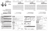
Figure 1.
Typical
ASSE 1069
Application
Cold
Hot
LFLM495
Mixed
LM495-4
COLD WATE
R
SUPPLY
POWERS SERIES LM495 OR
LFLM495 WITH INTEGRAL
CHECKS AND SCREENS
HOT WATER SUPPLY
Figure 2.
Single/Two
Handle Faucet
Application
Advanced
Thermal Activation
WARNING
!
Read this Manual BEFORE using this equipment.
Failure to read and follow all safety and use infor-
mation can result in death, serious personal injury,
property damage, or damage to the equipment.
Keep this Manual for future reference.
FAILURE TO COMPLY WITH PROPER INSTALLATION
AND MAINTENANCE INSTRUCTIONS COULD
CONTRIBUTE TO THE VALVE FAILURE, RESULTING IN
INJURY AND/OR DEATH.
TO ENSURE THE ACCURATE AND RELIABLE OPERATION
OF THIS PRODUCT, IT IS ESSENTIAL TO:
• Properly design the system to minimize pressure and
temperature variations.
• This valve is not factory preset and can be adjusted
to deliver scalding temperatures. Check outlet tem-
perature to ensure it does not exceed 105°F (41°C).
Make sure temperature limit stop is properly re-set to
maximum 105°F (41°C) following valve maintenance or
repair. Tampering with limit stop in any way may result
in scalding temperature causing serious bodily harm
and/or death.
WARNING
!
WARNING
!
Need for Periodic Inspection and Yearly Maintenance:
Periodic inspection and yearly maintenance by a licensed
contractor is required. Corrosive water conditions
and/or unauthorized adjustments or repair could render
the valve ineffective for service intended. Regular checking
and cleaning of the valve’s internal components and check
stops helps assure maximum life and proper product func-
tion. Frequency of cleaning and inspection depends upon
local water conditions.
You are required to consult the local building and plumbing
codes prior to installation. If the information in this manual is
not consistent with local building or plumbing codes, the local
codes should be followed. Inquire with governing authorities for
additional local requirements.
WARNING
!
WARNING
!
Flush all pipes thoroughly before installation. Installation and
field adjustment are the responsibility of the installer.
Installation Instructions

Making a Good CrimpRing
™
Connection n
1. Cut the pipe to length, making sure that you have a good square
cut. A rough, jagged, or uneven cut will result in a weakened
joint.
2. Next slide the correctly sized CrimpRing
™
over the end of the pipe
and down about 2".
3. Then slide the pipe over the fitting until the pipe touches the fit-
ting shoulder.
4. Now slide the CrimpRing
™
over the end of the pipe until it is
1
⁄8"
to
1
⁄4" from the end of the pipe. This positions the ring so that it is
directly over the two ribs closest to the end of the fitting.
5. Now position the tool so that it is at a 90° angle to the pipe, and
its jaws completely cover the ring.
6.Close the jaws completely.
7. Check to see that the “Go” slot of the Go/No-Go gauge slides
across the CrimpRing
™
. If the CrimpRing
™
doesn’t fit through the
“Go” slot then the ring wasn’t compressed sufficiently. Cut out
the joint, calibrate the tool, and make a new connection.
Installer Tip 1. Try a slight squeeze of the CrimpRing
™
with the channel-
lock pliers to keep it in place. Then you use your crimp tool to make the
final connection. You’ll find this especially helpful in vertical installations.
Other ASTM F2098 and F1807 Crimp Ring may be used.
Follow manufacturer's instructions carefully.
1. Check each connection by pushing the crimp gauge onto the
crimped copper ring at the appropriate “Go” slot. If it won’t fit
through, the ring wasn’t compressed enough. If the ring fits
through the “No-Go” slot, the ring was compressed too much.
If your connection fails this test, cut out the bad joint and start
over. Don’t try to run it through the crimp tool a second time. If
the gauge “hangs up” where the tool jaws closed (you’ll see a
small mark there), test the joint at
a different point before you fail the connection and make
the connection over.
2.
You must hold the gauge at a 90° angle to the ring to
perform a good test.
3. Always check to make sure you’re using the right size
opening in the gauge for the size pipe you’re installing.
4.Push the gauge right onto the crimped ring; don’t slide it!
5. Don’t change the gauge opening. It is manufactured to 0.002 tol-
erance to help protect your good reputation.
Buy a new gauge if your old one is damaged.
Bad Crimps Good Crimps
No-Go
Ring
compressed
too small.
Go
No-Go
Go
Ring not
com-
pressed
small
enough.
Will
not
go in
“No-
Go”
slot.
Will fit
in
“Go”
slot.
Illustration of a Good CrimpRing
™
Connection
1
1
3
3
4
2
2
5
No-go
Go Go
Go
No-go
No-go
Crimp Gauge
How to Test a CrimpRing
™
Connection
1. Fitting Shoulder location.
2. Pipe is cut square and stops at the fitting shoulder.
3. CrimpRing
™
is positioned
1
⁄8"–
1
⁄4" from end of the pipe,
directly over two end ribs of fitting.
4. CrimpRing
™
is evenly compressed over the pipe, and shows no
evidence of uneven distortion.
5. The WaterPEX
®
material is uniformly compressed between the
brass ribs, resulting in a leak-free, quality joint.
Using a CrimpRing
™
Gauge n
Using the CrimpRing
™
Gauge (Go/No-Go gauge) helps ensure a
quality joint. It has six openings, two for each size of pipe it ts.
These are for
3
⁄8",
1
⁄2", and
3
⁄4" (10, 15, 20mm) pipe sizes. See the fol-
lowing illustrations for guidance on how to use this important tool.
Always check every joint you make.
Making a Good Cinch Clamp Connection n
Place PEX cinch clamp nub between tool jaws and ratchet the
clamp until the PEX Cinch Clamp Tool auto-releases. This action
will assure that the PEX cinch clamp is fully clamped.
10
Watts Radiant reserves the right to change pricing and/or increase package quantities without notice.
All orders are FOB shipping point.
These connections are a cinch to make.
Our new CinchClamp boldly goes where those other fittings can’t — mainly
into tight, hard-to-reach spaces. With a unique “tab” design, there is no need
to get a tool around the entire fitting. Simply press the tab closed with the
CinchTool
™
and the connection is complete.
This design offers a positive mechanical connection, ensuring the PEX is
uniformly compressed against the fitting. The ratcheting CinchTool only releases
when proper assembly is complete. No guess work is needed to determine if the
connection has been properly made.
The unique CinchClamp design makes the new CinchTool dramatically
simpler and easier to use. One tool installs all sizes from 3/8" to 1".
The CinchClamp connection
system needs only one tool
for all clamp sizes.
CinchTool measures 11"L x 3"W x 3/4"H
Why it’s a cinch:
• Ratcheting tool provides easy one-tool assembly.
• Connections can be dry-fit.
• Connections can be made with wet tubing.
•Final connections take only seconds.
• CinchTool only releases when connection is
complete, ensuring a perfect connection.
• No calibration required on the CinchTool.
• Can visually verify whether connection
is completed – tab of clamp is
“pinched”.
• Connection rated to 160 psi
@73°F; 100 psi @ 180°F.
•Clamp is an interlocking ring,
forming a complete 360°
uniform, watertight seal.
• Corrosion resistant,
annealed stainless steel.
• Uses ASTM F1807 brass or ASTM F2159 plastic insert fittings (plastic for
potable systems only).
•
Warning: To ensure a perfect seal, the PEX pipe must be 32°F or warmer when
the CinchClamp is applied.
EST. SHIP
DESCRIPTION QTY. MODEL NUMBER ORDER NUMBER WT. (LBS.) LIST PRICE
3/8" CinchClamps 10 PCCC2X-10 81004993 1 $3.80
3/8" CinchClamps 100 PCCC2X-100 81004994 1 $38.00
1/2" CinchClamps 10 PCCC3X-10 81004995 1 $3.80
1/2" CinchClamps 100 PCCC3X-100 81004996 1 $38.00
5/8" CinchClamps 10 PCCC6X-10 81005114 2 $5.20
5/8" CinchClamps 100 PCCC6X-100 81005115 3 $52.00
3/4" CinchClamps 10 PCCC4X-10 81004997 2 $4.80
3/4" CinchClamps 100 PCCC4X-100 81004998 3 $48.00
1" CinchClamps 10 PCCC5X-10 81005001 2 $5.90
1" CinchClamps 100 PCCC5X-100 81005002 3 $59.00
CinchTool 1 PCCCT5 81004999 3 $187.00
Introducing the New CinchClamp
™
Radiant PEX

Tu rn
Hotter
Hex Wrench
Colder
Unscrew, Lift Cap
to Adjust
Figure 3.
1. Let the water flow for at least two minutes to allow supply tem-
perature to stabilize.
2. Place a thermometer in the outlet water stream.
3. Loosen handle screw with hex wrench.
4. Handle must be lifted
1
⁄4” to adjust temperature. Rotate handle
clockwise to decrease temperature and counter-clockwise to
increase the temperature.
5. Lower handle and tighten screw.
6. Check for outlet temperature.
NOTICE
Pressure Differential between Hot & Cold Water Supplies must be
less then 25%.
NOTICE
It is recommended that shutoff valve(s) be installed on the inlet(s) to
facilitate service of the LFLM495 valve.
Model Part # Description
LFLM495 495 100 Plunger/Motor Assembly
WARNING
!
For valves with CPVC or PEX end connections, do not exceed
the tubing manufacturers pressure and temperature ratings.
Refer to the tubing manufacturers product specications for that
information.
Repair Kit n
Troubleshooting n
Fluctuating or erratic hot water temperature at fixture:
Unbalanced pressure. Install balancing or throttling valve at the
hot and cold water supplies and adjust accordingly for demand.
Hot water backing up into cold water line:
Hot water pressure is higher than cold water pressure.
Examine check valves for dirt & debris, clean as necessary.
Cannot adjust water temperature to desired temperature:
Install balancing or throttling valve at the hot and cold water sup-
plies and adjust accordingly for demand.
High pressure drop through the tempering valve:
Valve undersized. Install larger thermostatic tempering valve.
Insufficient hot water during peak demand:
Check flow requirement during peak demand period. Use larger
thermostatic tempering valve.
To Adjust Temperature (Figure 3) n

USA: Tel: (800) 669-5430 • Fax: (847) 229-0526 • www.powerscontrols.com
Canada: Tel: (888) 208-8927 • Fax: (888) 479-2887 • www.powerscontrols.ca
Latin America: Tel: (52) 81-1001-8600 • watts.com
IS-P-LM495-PEX 1423 EDP# 2915168 © 2014 Powers
Warranty n
The Seller warrants that the equipment manufactured by it and covered by this order or contract is free from defects in material and workmanship and, without
charge, equipment found to be defective in material or workmanship will be repaired, or at Seller’s option replaced F.O.B. original point of shipment, if written
notice of failure is received by Seller within one (1) year after date of shipment (unless specifically noted elsewhere), provided said equipment has been properly
installed, operated in accordance with the Seller’s instructions, and provided such defects are not due to abuse or decomposition by chemical or galvanic action.
THIS EXPRESS WARRANTY IS IN LIEU OF AND EXCLUDES ALL OTHER WARRANTIES, GUARANTEES, OR REPRESENTATIONS, EXPRESS OF IMPLIED. THERE ARE
NO IMPLIED WARRANTIES OF MERCHANTABILITY OR OF FITNESS FOR A PARTICULAR PURPOSE. The Seller assumes no responsibility for repairs made on the
Seller’s equipment unless done by the Seller’s authorized personnel, or by written authority from the Seller. The Seller makes no guarantee with respect to material
not manufactured by it.
A Watts Water Technologies Company
WARNING: This product contains chemicals known to the
State of California to cause cancer and birth defects or
other reproductive harm.
For more information: www.watts.com/prop65
/