Page is loading ...


www.uponor-usa.com • www.uponor.ca
2
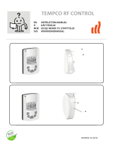
Uponor Climate Co˘ntrol
Zoning System Installation Guide
Published by Uponor, Inc.
5925 148th Street West
Apple Valley, MN 55124 USA
Phone: (800) 321-4739
Fax: (952) 891-2008
www.uponor-usa.com
© 2010 Uponor
All Rights Reserved.
First Edition
First Printing May 2008
Printed in the United States of America

Uponor Climate Co˘ntrol™ Zoning System Installation Guide i
Note: This equipment has been tested and found
to comply with the limits for a Class B digital device,
pursuant to part 15 of the FCC Rules. These limits are
designed to provide reasonable protection against
harmful interference in a residential installation.
This equipment generates, uses and can radiate radio
frequency energy and, if not installed and used in
accordance with the instructions, may cause harmful
interference to radio communications. However, there
is no guarantee that interference will not occur in a
particular installation. If this equipment does cause
harmful interference to radio or television reception,
which can be determined by turning the equipment
off and on, the user is encouraged to try to correct the
interference by one or more of the following measures:
• Reorient or relocate the receiving antenna
• Increase the separation between the equipment
and receiver
• Connect the equipment into an outlet on a
circuit different from that to which the receiver is
connected
• Consult the dealer or an experienced radio/TV
technician for help
Operation is subject to the following two conditions:
(1) this device may not cause interference, and (2)
this device must accept any interference, including
interference that may cause undesired operation of
the device.


Uponor Climate Co˘ntrol™ Zoning System Installation Guide iii
Table of Contents
The Uponor Climate Co˘ntrol Zoning
System Installation Guide
Section 1: General Recommendations . . . . . . . . . . . . . . 1
Safety Measures . . . . . . . . . . . . . . . . . . . . . . . . . . .1
Symbols Used in This Manual . . . . . . . . . . . . . . . . . . . . . . 1
Power Supply . . . . . . . . . . . . . . . . . . . . . . . . . . . . 1
Limitations for Radio Waves . . . . . . . . . . . . . . . . . . . . . . 1
Technical Constraints . . . . . . . . . . . . . . . . . . . . . . . . .1
Section 2: The Uponor Climate Co
˘ntrol Zoning
System Overview. . . . . . . . . . . . . . . . . . . . . . . . . . . . . . . 3
Thermostat Display T-75 . . . . . . . . . . . . . . . . . . . . . . . . 3
Base Unit With Antenna and Actuators . . . . . . . . . . . . . . . . . .3
Interface I-75 . . . . . . . . . . . . . . . . . . . . . . . . . . . .3
Uponor Climate Co˘ntrol Zoning System Components . . . . . . . . . . . . .4
Section 3: Base Unit Installation . . . . . . . . . . . . . . . . . . 5
Base Unit Diagram . . . . . . . . . . . . . . . . . . . . . . . . . .5
Preparation Before Installation . . . . . . . . . . . . . . . . . . . . . 5
Components Installation . . . . . . . . . . . . . . . . . . . . . . . . 6
Section 4: Thermostat Installation ................11
Label the Room Thermostats . . . . . . . . . . . . . . . . . . . . . 11
Register Room Thermostats . . . . . . . . . . . . . . . . . . . . . 12
Determining the Thermostat Location. . . . . . . . . . . . . . . . . . 13
Mounting the Thermostat . . . . . . . . . . . . . . . . . . . . . . 13
Section 5: Thermostat and Base Unit Testing . . . . . . . 15
Testing the Communication Between Thermostats and Base Unit . . . . . . . 15
Testing the Base Unit Actuator . . . . . . . . . . . . . . . . . . . . 16
Final Inspection . . . . . . . . . . . . . . . . . . . . . . . . . . 16
Section 6: Interface with Base Unit Installation .....17
Example of an Installation . . . . . . . . . . . . . . . . . . . . . . 17
Interface Bracket Installation . . . . . . . . . . . . . . . . . . . . . 18
Wiring and Programming the Interface . . . . . . . . . . . . . . . . . 19
Connections . . . . . . . . . . . . . . . . . . . . . . . . . . . 20
Time and Date Setup . . . . . . . . . . . . . . . . . . . . . . . . 22
Attaching the Interface to Bracket . . . . . . . . . . . . . . . . . . . 23
Interface Setup . . . . . . . . . . . . . . . . . . . . . . . . . . 23
Installation Inspection. . . . . . . . . . . . . . . . . . . . . . . . 24
Alarms. . . . . . . . . . . . . . . . . . . . . . . . . . . . . . 24
Resetting the Interface . . . . . . . . . . . . . . . . . . . . . . . 24

www.uponor-usa.com • www.uponor.ca
iiii
Table of Contents (continued)
Section 7: Thermostat Operation .................25
Thermostat T-75 Display . . . . . . . . . . . . . . . . . . . . . . . 25
Changing the Temperature Format . . . . . . . . . . . . . . . . . . . 25
Changing the Temperature Setpoint . . . . . . . . . . . . . . . . . . 25
Setting the Minimum and Maximum Temperatures. . . . . . . . . . . . . 26
Thermostat Battery Replacement . . . . . . . . . . . . . . . . . . . 26
Section 8: Interface Operation ...................27
Interface Screens. . . . . . . . . . . . . . . . . . . . . . . . . . 28
Access Level . . . . . . . . . . . . . . . . . . . . . . . . . . . 28
Information Menu . . . . . . . . . . . . . . . . . . . . . . . . . 29
Room Temperature . . . . . . . . . . . . . . . . . . . . . . . . . 29
ECO (Economy) . . . . . . . . . . . . . . . . . . . . . . . . . . 29
Battery and Communication Status. . . . . . . . . . . . . . . . . . . 29
Thermostat and Actuator Status . . . . . . . . . . . . . . . . . . . . 29
Actuator Status . . . . . . . . . . . . . . . . . . . . . . . . . . 29
Settings menu. . . . . . . . . . . . . . . . . . . . . . . . . . . 30
Information Menu: System Information . . . . . . . . . . . . . . . . . 30
ECO Mode . . . . . . . . . . . . . . . . . . . . . . . . . . . . 30
Steps to Follow . . . . . . . . . . . . . . . . . . . . . . . . . . 30
Heating . . . . . . . . . . . . . . . . . . . . . . . . . . . . . 30
Editing the ECO Proles . . . . . . . . . . . . . . . . . . . . . . . 31
Apply ECO Prole . . . . . . . . . . . . . . . . . . . . . . . . . 31
Setting Time and Date . . . . . . . . . . . . . . . . . . . . . . . 31
Exercise Actuators and Pumps . . . . . . . . . . . . . . . . . . . . 32
Temperature Unit . . . . . . . . . . . . . . . . . . . . . . . . . 32
Backlight. . . . . . . . . . . . . . . . . . . . . . . . . . . . . 32
Installer Level . . . . . . . . . . . . . . . . . . . . . . . . . . . 32
Vacation Mode . . . . . . . . . . . . . . . . . . . . . . . . . . 32
Section 9: Technical Data . . . . . . . . . . . . . . . . . . . . . . . 33
Base Unit Connection Diagrams . . . . . . . . . . . . . . . . . . . . 34
Section 10: T-54 Installation and Operation . . . . . . . . 37
Section 11: System Maintenance .................41
Section 12: Troubleshooting .....................43
Normal System Operating Conditions . . . . . . . . . . . . . . . . . . 43
Identifying and Resolving Alarms and Errors . . . . . . . . . . . . . . . 43
Contacting an Installer . . . . . . . . . . . . . . . . . . . . . . . 44
Contacting Uponor . . . . . . . . . . . . . . . . . . . . . . . . . 44
Troubleshooting Solutions . . . . . . . . . . . . . . . . . . . . . . 45
Section 13: Installation Report . . . . . . . . . . . . . . . . . . 51

Uponor Climate Co˘ntrol™ Zoning System Installation Guide 1
Section 1
General
Recommendations
Safety Measures
• Read and follow the instructions in this guide.
• Installation must be performed by a qualied person
according to local code.
• It is prohibited to make changes or modications not
specied in this guide.
• Power must be switched off when wiring.
• Uponor is not responsible for damages and
breakdowns that may result from not following the
instructions in this guide.
Symbols Used in This Manual
Warning: Risk of bodily injuries.
Nonobservance may harm health or cause
damage to product components.
Caution: Important note on functionality
Information: Important operating advice
and information
See another document.
99
See another page in the manual.
Extended function with the interface
�
Result of an action
>
Press button
LED off
LED on
LED blinks
LED ickers
Power Supply
• The Uponor Climate Co˘ntrol™ Zoning System
uses a 110VAC/60Hz power supply.
• In case of emergency, immediately disconnect
the plug from the power.
• Do not use water to clean the Zoning System.
• Switch off power when wiring.
• Do not expose the Zoning System to ammable
vapors or gases.
Limitations for Radio Waves
The Zoning System uses radio waves. The frequency
used is reserved for similar applications, and the
chances of interference from other radio sources is
very low. However, in some rare special cases, it may
not be possible to establish a perfect communication.
The transmission range is sufcient for most
applications, but each building has different
obstacles affecting communication and maximum
transmission distance. If communication trouble exists,
Uponor can support the system with accessories, such
as repeaters, for solving the exceptional issues.
Technical Constraints
• Keep installation and data cables away from power
cables greater than 50VAC to avoid interference.
• The electrical circuits of the boiler and the pump
must be protected by a maximum 10A circuit breaker.


Uponor Climate Co˘ntrol™ Zoning System Installation Guide 3
Section 2
The Uponor Climate
Co
˘ntrol Zoning System
Overview
The Uponor Climate Co˘ntrol Zoning System is a
wireless zoning control for radiant oor systems.
Comfort, user-friendliness and temperature control
for each room can be combined through the different
components.
The control system consists of:
• Thermostat T-75
• Base Unit C-55 with antenna and actuators
• Interface I-75 (optional)
The Uponor Zoning System is controlled by wireless
thermostats. The thermostats communicate with base
units via radio waves.
Thermostat Display T-75
The thermostat displays the temperature
on its screen. The thermostat is affected
by the temperature of surrounding
surfaces as well as the ambient air
temperature. A thermostat calls for heat
by sending a signal to the base unit. The
base unit then activates the channels
linked to that thermostat, powering the actuators
mounted on the manifold.
Base Unit With Antenna
and Actuators
The base unit controls the actuators based
on the requirements from each zone
thermostat. Each base unit is capable of
controlling up to 12 thermostats and
14 actuators. The base unit is typically
located near the manifolds.
Interface I-75
The interface allows viewing of important
zone information and setting of vacation/
setback schedules from a remote location.
The interface also can display alarms such
as low battery, no connection, etc.

www.uponor-usa.com • www.uponor.ca
4
Uponor Climate Co˘ntrol Zoning System
Components
Thermostat
DisplayT-75
Base Unit C-55
Antenna for
Base Unit C-55
Base Unit C-55
Base Unit C-55
Antenna
Installation guide
Fastening screws
Adhesive strip
Connection cable
for antenna (1 ft.)
Connection cable
for antenna (10 ft.)
Connection cable
for interface
Interface
Language data stick
Interface bracket
Thermostat display T-75
Batteries
Table stand
Wall bracket
Adhesive strip
Fastening screws
Thermostat
Display T-75
Thermostat
Mounting Kit
forT-75

Uponor Climate Co˘ntrol™ Zoning System Installation Guide 5
Section 3
Base Unit Installation
Base Unit Diagram
Preparation Before Installation
Review the wiring diagram located inside the base
unit cover.
Verify Contents
• Cordless electric drill
• 6mm (1¼") drill bit
• Small athead screwdriver
• Phillips screwdriver
Review Drawings
Review the drawings of the radiant oor heating system.
If the locations of the base units and thermostats are not
specied, determine the best positions.
• Install base unit with antenna close to each manifold.
• A 110VAC standard power receptacle is required for
the connection of the base unit.
• Protect the mounting locations for the Zoning System
from moisture.
• Use one thermostat for every zone with radiant
oor heating.
Terminal block for connection
of antenna and extensions
for additional I-75 interface
Interface RJ 9
connector for I-75
Push button and LED from
01 to 12 for channel registration
Test button with LED
Quick connectors for
the actuators
Socket for the connection
of the data stick
Power LED
110v/60Hz Compartment – Heat-demand Relay
110V
0201
110V
A3601012 C-55
IP30
T55
Made in France

www.uponor-usa.com • www.uponor.ca
6
Components Installation
Mounting the Base Unit Antenna
Decide if the antenna should be mounted on the back of
the base unit or on the wall.
Caution: If the base unit is installed inside a
metal manifold cabinet, place the end or the
entire antenna outside the cabinet.
Clip the Antenna Into the Back of the Base Unit
1. Use a one-foot antenna cable.
2. Connect the RJ 9 connector into the antenna.
3. Clip the antenna into the base unit.
4. Insert the cable of the antenna into the hole of the
base unit.
�
Connect to terminals 9 and 10.
#09
#10

Uponor Climate Co˘ntrol™ Zoning System Installation Guide 7
Fastening the Antenna to the Wall with Screws
1. Connect the RJ 9 connector into the antenna.
2. Using a drill bit, drill the wall.
3. Fix anchor and screw to the wall. Let the screw
protrude from the wall.
4. Fasten the antenna on the screw.
Fastening the Antenna to the Wall with Adhesive
1. Connect the RJ 9 connector into the antenna.
2. Use the double-sided adhesive strip to attach the
antenna to a smooth wall, such as glazed ceramic tiles.
10 feet
10 feet

www.uponor-usa.com • www.uponor.ca
8
Mounting the Base Unit
• Position the base unit just above the manifold.
Ensure the power receptacle is within reach of
the base unit's power supply cord.
• Check that the base units cover can be
removed easily.
• Check that the connectors and switches are
easily accessible.
Caution: Mount the base unit horizontally.
There is a risk for overheating if the base unit is
mounted vertically or on a at surface.
1. Hold base unit to wall; mark mounting hole locations
on the wall with a pencil.
2. Drill the wall.
3. Press the anchor into the hole.
4. Attach the base unit to the wall with screws.
Information: Each thermostat can control any
number of channels. Installation and
maintenance are simplied if actuators
controlled by the same thermostat are wired to
channels in sequence.

Uponor Climate Co˘ntrol™ Zoning System Installation Guide 9
Resetting the Base Unit
Resetting the base unit will cancel all channel
registrations, allowing the user to change all
the registrations.
1. Press the Test button for 10 seconds.
2. The Test LED ashes for at least two seconds,
then all LEDs will turn off (except the power LED).
All parameters are erased.
3. New installation and registration after reset
is necessary.
Installation Example
• Thermostat/Zone #01 controls two actuators
connected to channels 1a and 1b.
• Channel 2a and 2b are not used in this diagram.
• Thermostat/Zone #02 controls two actuators
connected to channels 3 and 4.
• Thermostat/Zone #03 controls one actuator
connected to channel 5.
• Thermostat/Zone #04 controls one actuator
connected to channel 6.
• Thermostat/Zone #10 controls three actuators
connected to channels 10, 11 and 12.
Warning: Disconnect the power before
installing or changing the device wiring.
Powering the Base Unit
• Check the actuators and antenna to
ensure that the wiring is complete.
• Check that the power compartment
lid is closed.
• Connect the power
supply plug into the
electrical outlet.
Zones
Channels


Uponor Climate Co˘ntrol™ Zoning System Installation Guide 11
Section 4
Thermostat Installation
The Zoning System is controlled by the
Thermostat Display T-75.
Label the Room Thermostats
• Install two alkaline AAA 1.5V batteries in each
thermostat (see page 26).
• Label the thermostats with the channel numbers they
are to control, e.g., 02, 03, etc. For a system with an
interface and several base units, an identication for
the base unit should be added, e.g., 1.02, 1.03, 2.02,
2.03, etc.
Thermostat
Display T-75
T-75

www.uponor-usa.com • www.uponor.ca
12
Register Room Thermostats
An example of registering a thermostat: one thermostat
controls two actuators that connect channels 02 and 03.
1. Push the Test button.
�
The Test button LED lights up .
2. Push channel button 02.
3. Push channel button 03.
�
The LEDs of channels 02 and 03 will ash .
4. Using a small pointed tip, press the thermostat’s
registration button, located on the bottom of the
thermostat, for at least ve seconds.
For Thermostat Display T-75:
• The thermostat displays two lines.
• Release the button when the temperature reappears.
5. LED will ash and turn solid, indicating a
successful link.
Repeat the same sequence for all thermostats.
�
The Test LED switches off .
LED LED Status
LED on
LED ash
LED off
Cancelling the Registration of a Channel
1. Press the Test button.
�
The Test and channel LEDs with registered
thermostats light up .
2. To cancel, press the channel button for 10 seconds.
�
The LED of the cancelled channel ashes for two
seconds, then switches off .
3. Press the Test button to exit registration mode.
�
The Test LED switches off .
Caution: To register a different thermostat
to a channel, cancel the registration of the
existing thermostat prior to linking to new
thermostats. Then repeat the steps as outlined
in the Register Room Thermostats section
on this page.
5 seconds
5
5 seconds
5

Uponor Climate Co˘ntrol™ Zoning System Installation Guide 13
Determining the Thermostat Location
• On an indoor wall
• 5' from the oor
• Away from any source of moisture
• Away from any source of heat
• Away from direct sunlight
Mounting the Thermostat
There are two ways to mount a thermostat:
• Direct mounting (using screws or adhesive strips)
• Thermostat mounting kit (includes table stand,
wall bracket, adhesive strips, screws and batteries)
Mounting Using Screws or Brackets
1. Screws should protrude from the wall.
2. Hang the thermostat on the screws.
3. When using the mounting kit bracket, mount
bracket to the wall, then hang thermostat
on bracket.
Mounting Using Adhesive Strips
1. Use the double-sided adhesive strip to x the
thermostat on a smooth wall, such as glazed
ceramic tiles.
5 feet
Mounting Directly to the Wall Mounting to the Bracket

/