
NOTE: Detailed information on the PIKO SmartDecoder XP 5.1 Sound is available as a PDF le on our
Webshop on the page of the respective item number. The le contains a full description of all functions
and operating possibilities for the new SmartDecoder XP 5.1 Sound.
Description
The state-of-the-art PIKO SmartDecoder XP 5.1 Sound Next18 inside in this PIKO locomotive is a compact yet powerful
multi-protocol PluX22 sound decoder. It features high delity, 12 bit 8-channel sound with 2.5 watts of output that
ensures distortion-free sound at all levels. It complies with the current RCN standards in all areas and can be used
in DCC- and Motorola® digital systems. The decoder can be used on DCC, mfx®, and Motorola® digital systems as
well as traditional DC or AC analog layouts. It automatically senses what operating mode is used on your layout and is
RailCom®/RailCom Plus® compatible. The PIKO SmartDecoder XP 5.1 Sound features several programmable braking
distance functions in addition to numerous other programmable functions.
The PIKO SmartDecoder XP5.1 Sound is load-regulated and features auto-adaptive motor control that works with of
a fundamentally newly developed traditional DC motors for a silky smooth ride as well as 1.2 Amp coreless motors.
The decoder will also tolerate a temporary current draw up to 1,5 Amps. The motor speed table can be set using the
minimum, median, and maximum motor speed (simple curve), or by the user-programable 28-speed step extended
curve. The decoder features two directional lighting outputs and four (of which two logic) additional special function
outputs that can be activated using function keys up to F68 (DCC). The switching (shunting) gear, with extended slow
speed range, the three possible starting and braking delays, as well as the many vehicle sounds are also switchable
via function keys. The sound part can control specied function outputs as well as the motor output of the decoder.
For example, the lighting of a diesel locomotive ickers when the engine is started. The PIKO SmartDecoder XP 5.1 is
supported by the further developed power management in case of short-term voltage loss.
Installing the PIKO SmartDecoder XP 5.1 Sound
Remove the jumper plug from your model’s PluX22 interface. Insert the new sound decoder into the interface socket.
The plug-in direction is usually marked on the interface socket marked. Note that PIN 11 is missing on the new decoder.
Please install the loudspeaker as shown in the graphic of the "Spare parts list". Check for crossed wires and short circuits
before and after reinstalling the shell. Place the model on your programming track with programming mode activated on
your DCC system. During programming or when reading the model’s DCC address, a small amount of current will ow
through the model, which does not affect the decoder; even in the event of a short circuit.
Special function outputs A1 to A4
The decoder’s special function outputs A1 to A4 can only be activated if the desired functions are already connected to
the model’s Next18 interface or if solder pads are available for the special function outputs on the main circuit board.
Outputs A3 & A4 provide logic levels and must be wired accordingly on the main board be connected.
First-time use of the decoder (state of delivery)
Enter address 3 on your digital control system. Depending on the data format used to address the sound decoder,
the locomotive runs in DCC mode with 28 speed steps or in Motorola® mode. When using a RailCom Plus® capable
digital control center the decoder is detected automatically and can be operated immediately. If the decoder is used
on a conventional analog layout, it can be controlled with a DC or AC power pack. The decoder will automatically
detect the layout’s operating mode.
NOTE: In DC mode, your vehicle will not start until the voltage is higher (speed control turned up further) than you
may have been used to when operating with analog vehicles.
Function outputs in analog mode
It is possible to program the decoder so that function keys F0 - F12 (as they are assigned in the function
mapping) can also be activated in analog mode. To do this, CVs 13 & 14 must rst be programmed with a DCC
central control unit. The corresponding values can be found in the CV table of the detailed operating instructions.
The light function F0 and the engine noise F1 are switched on at the factory.
#46553 PIKO SmartDecoder XP 5.1 Sound Next18
for Electric locomotives BR S 499.02
È
SD TT
multiprotocol
46553-90-7001_2023
Function assignments
PIKO Spielwaren GmbH
Lutherstr. 30
96515 Sonneberg
GERMANY
A short circuit in the motor, lighting, pick-up wiper, or wheelsets can destroy the
decoder as well as the electronics of the model!
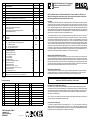
CV Description Area Value*
1Locomotive address
DCC: 1 - 127
Mot: 1 - 80
3
2Minimum speed (the speed from 0 until the locomotive is running at speed step 1) 0 - 255 1
3Acceleration delay 0 - 255 30
4Braking delay 0 - 255 40
5Maximum speed (must be greater than CV 2) 0 - 255 212
6Average speed (must be greater than CV 2 and less than CV 5) 0 - 255 70
7Firmware version (The processor can be updated) - differently
8Manufacturer's ID Decoderreset CV8 = 8
different
162
12
Decoder operating mode
Bit 0=1 DC (analog operation; direct current) on
Bit 2=1 DCC data format on
Bit 4=1 AC (analog 3-rail operation; alternating current) on
Bit 5=1 Motorola® data format on
Value
*1
*4
*16
*32
0 - 117
53
17
18
Long locomotive address
17 = high Byte
18 = low Byte
1 - 10239
192 - 231
0 - 255
1000
195
232
27
Brake signal settings (automatic stop)
Bit 0 = 1 -> ABC (Automatic Brake Control) right rail positive
Bit 1 = 1 -> ABC left rail positive
Bit 4 = 1 -> DC; opposite direction of travel
Bit 5 = 1 -> DC; same direction of travel
Value
1
2
16
32
0 - 51 0
29
DCC standard conguration
Bit 0=0 Normal direction of travel
Bit 0=1 Opposite direction of travel
Bit 1=0 14 speed steps
Bit 1=1 28 speed steps
Bit 2=0 Digital mode only
Bit 2=1 Automatic analog/digital recognition
Bit 3=0 RailCom® turned off
Bit 3=1 RailCom® turned on
Bit 4=0 Speed steps over CV 2, 5, and 6
Bit 4=1 Use the characteristic curve from CV 67 - 94
Bit 5=0 Short address (CV1)
Bit 5=1 Long address (CV 17/18)
Value
*0
1
0
*2
0
*4
0
*8
*0
16
*0
32
0 - 63 14
30 Error codes for the motor, thermal overload, and function outputs:
1 = motor error, 2 = thermal overload error, 4 = function output error 0 - 7 0
* set ex works
F0 Light F10 Whistle F20 Auxiliary Air Compressor
F1 Traveling Sound F11 Fan F21 Compressor
F2 Horn F12 Curve Squeal F22 Main Switch
F3 Cab Light F13 Clickety-Clack F23 Pantograph
F4 Engine Room Lights F14 Volume Regulator F24 Cab Window
F5 High Beam * F15 Station Announcement F25 Cab Door
F6 Signal light * F16 Radio Chatter 1 F26 Engine Room Door
F7 Switching Gear F17 Radio Chatter 2 F27 Sanding
F8 Train Lighting: Engine pulling F18 Coupling F28 -
F9 Train Lighting: Engine pushing F19 Tunnel mode
* version-dependent

Motorola®
The decoder utilizes 4 Motorola® addresses to access functions F1 - F 16, when using a Motorola—based
command station. The three sequence addresses for the functions F5 - F16 are ascending to the decoder address
and can be activated in CV61 as required by the values 1 (F5 - F8), 2 (F5 - F12), or 3 (F5 - F16).
Conguration of CVs
CVs 12 and 29 control the operating mode and conguration CVs, respectively. As a rule, an indexed CV contains
various basic settings of a decoder, such as reversing the direction of travel. CV calculation examples can be found
in the detailed operating instructions.
RailCom®, RailCom Plus®
In the sound decoder, CV29 (RailCom®) can be turned on or off via bit 3. The decoder is automatically recognized
by RailCom Plus® - equipped command stations (like PIKO SmartControl) if the RailCom Plus® option is activated
in CV 28. The decoder name, locomotive symbol, and special function symbols will appear automatically on your
control device’s screen. With RailCom Plus® technology, no locomotive data has to be stored in the DCC central
control unit and no locomotive addresses have to be programmed into the decoder.
Braking
The sound decoder understands the following braking methods:
Märklin® braking section (brakes with analog DC voltage)
DCC braking function
ABC (Automatic Brake Control) braking section
The decoder’s adjustable braking distance can bring the train to a stop within a centimeter of a signal. More
information on "braking behavior" can be found in the detailed operating instructions for
PIKO SmartDecoder XP 5.1 Sound.
Function outputs
A comprehensive description of all options related to the function outputs can be found in the detailed operating instructions.
Simple and extended function mapping
Easy-to-use function mapping allows you to assign functions like lighting and other outputs to any key between
F0 – F12. Acceleration, braking delay, and switching (shunting) mode can be assigned to any function keys using
CVs 156 and 157.
Smoke generator control
A smoke generator can be connected to the outputs A1 to A2, which is load-dependent (factory setting) and reacts
to the speed dependency of the model. Function key assignment is done using extended function mapping.
Extended function mapping
Due to its complex nature, extended function mapping cannot easily be set by programming individual CVs. To
work with extended function mapping, you will need the PIKO SmartProgrammer device (#56415) and, if desired,
the PIKO SmartTester (#56416). Detailed information on extended function mapping is available in the instruction
manual.
Servo control
The sound decoder enables the control of servo motors via the function outputs A1 and A2. The assignment to the function
keys is done exclusively via the extended function mapping.
The use of a servo with the decoder requires electronics expertise.
Further information can be found in the detailed operating instructions.
ATTENTION: Soldering on the decoder should only be carried out by experienced specialists with the appropriate tools.
Decoders damaged by improper handling will not be covered by the warranty.
Sound settings
To change the overall sound volume of the SmartDecoder XP 5.1 Sound, rst program CV31 to a value of 16 and
CV32 to a value of 0.
This will take you to the programming area for setting the total volume. You can now set this as you wish in CV257 in the
value range 0 - 255.
NOTE: In order to play a PIKO sound on the sound decoder, the test and programming device requires PIKO
SmartProgrammer (#56415) and (optional) the PIKO SmartTester (#56416).
All further information about the sound section of the PIKO SmartDecoder XP 5.1 Sound as well as the available
For setting options, please refer to the detailed operating instructions.
Factory reset
To restore the sound decoder to its factory settings, program CV8 to a value of 8.
Programming
Conguration variables (CVs) form the basis of all the decoder’s settings. This decoder can be used with the PIKO
SmartControllight DCC system, the PIKO SmartControl DCC system, or any other Motorola-based system.
For more information on programming options, please refer to the instruction manual.
Märklin® is a registered trademark of Gebr. Märklin & Cie. GmbH, Göppingen
Motorola® is a registered trademark of Motorola Inc. Tempe, (Phoenix) Arizona / USA
RailCom® and RailComPlus® are registered trademarks of Lenz Elektronik GmbH, 35398 Gießen
NOTE: This product is not a toy and is not suitable for children under the age of 14. Any liability for damage of any
kind caused by improper use or failure to observe these instructions is excluded.
Service:
Internet: www.piko.de
E-Mail:[email protected]
Hotline: Di + Do 16-18 Uhr
In the event of a defective decoder, please return the decoder module to PIKO along with proof of purchase, the decoder
address, and a short description of the problem.
Warranty Statement
Each decoder module is fully tested before shipment. Nevertheless, should a malfunction occur within the 2-year warranty
period, we will repair the module free of charge on presentation of the proof of purchase. This warranty is voided if the unit
has been damaged by improper use. Please note that, according to the German Electromagnetic Compatibility Law (EMV-
Gesetz), the decoder module may only be used inside models bearing the CE mark.
Product subject to changes. All rights reserved. Printed 10/2023.
Copy and duplication of this text are permissible only with the permission of the publisher.
-
 1
1
-
 2
2

