Page is loading ...

IMPORTANT
READ ALL OF THE FOLLOWING WARNINGS AND
STATEMENTS BEFORE READING THE
INSTALLATION INSTRUCTIONS
WARNING
LIQUEFIED PETROLEUM (L.P.)
PROPANE GAS-FIRED BOILERS
Installation location ONLY as permitted in paragraph
entitled "LIQUEFIED PETROLEUM (L.P.) PROPANE
GAS-FIRED BOILER LOCATION" on page 4 of this
instruction book.
The above warning does not apply to NATURAL gas
fired boilers.
The installation must conform to the requirements of the
authority having jurisdiction or, in the absence of such
requirements, to the National Fuel Gas Code, ANSI Z223.1-
latest edition or CSA B149.1-00 for natural gas and
propane. The installation must also conform to the
additional requirements in this Slant/Fin Instruction Book.
In addition, where required by the authority having juris dic -
tion, the installation must conform to American Society of
Mechanical Engineers Safety Code for Controls and Safety
Devices for Automatically Fired Boilers, No. CSD-1 or CSA
B149.1-00 for natural gas and propane. If there is any
conflict in the above requirements, then the more stringent
requirement will apply.
WARNING
This boiler, gas piping and accessories must be
installed, connected, serviced and repaired by a
trained, experienced service technician, familiar with
all precautions required for gas-fired equipment and
licensed or otherwise qualified, in compliance with
the authority having jurisdiction.
WARNING
The venting system of this boiler is under positive
pressure. Leakage from this system can be hazardous
and if not avoided can result in death or serious injury. In
addition to the recommendations within this manual and
the User’s Information Manual, the venting system, from
the flue collector to the outdoor discharge, must be
carefully checked annually by a qualified service agency.
This manual must be left
with owner and should be
hung on or adjacent to the
boiler for reference.
LYNX
INSTALLATION AND OPERATING INSTRUCTIONS
Printed in Canada 0210 Part No. 84-5736 Publication No. LXA-40
Heating Contractor
Address
Phone Number
Boiler Model Number
Boiler Serial Number
Installation Date
DIRECT-VENT SEALED COMBUSTION CONDENSING BOILER
HOT WATER MODEL LX-85A
GAS-FIRED BOILER FOR NATURAL AND L.P. PROPANE GASES
TABLE OF CONTENTS
Dimensions, Rating and Orifice Sizes.................................................2
Identification of Parts ...........................................................................3
Installation Requirements....................................................................4
Contamination Prevention...................................................................5
Venting Application..............................................................................5
Boiler Room Air Supply and Ventilation ..............................................5
Flue gas Venting Requirements ..........................................................6
Vent Material .......................................................................................6
Air Intake Material ...............................................................................6
Vent and Air Intake Restrictions...........................................................7
Non-Direct Vent Installation .................................................................8
Sidewall Venting, Non-Direct Vent.......................................................8
Vent Termination Location and Clearance ..........................................8
Non-Direct Vent Vertical Venting .........................................................8
Direct Vent Installation .........................................................................8
Sidewall Venting, Direct Vent...............................................................8
Alternate Sidewall venting for direct or non-direct venting.........14
Vent/Air Intake Termination Installation .............................................15
Direct Vent, Venting and Air Intake through a Roof ..........................16
Venting and Air Intake Regular Inspection........................................17
Condensate Removal System...........................................................17
Gas Piping .........................................................................................17
Electrical Wiring .................................................................................18
Wiring Diagram..................................................................................19
Multi Zoning .......................................................................................21
Water Piping ......................................................................................24
Operating Instructions .......................................................................30
Boiler Control Display........................................................................30
Boiler Control.....................................................................................30
Sequence of Operation .....................................................................36
Gas Input Rate Adjustment ...............................................................37
Safety Check .....................................................................................38
Care and Maintenance ......................................................................41
General Troubleshooting Guide........................................................42
Appendix A&B ...................................................................................44
C

Lynx Model LX-85A
2
14 3/4
34 3/4
32 3/4
2 7/8
18
3 1/2
5
6 1/2
LEFT SIDE FRONT RIGHT SIDE
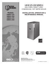
RATINGS AND DIMENSIONS
Figure 1. Dimensions data
Lynx Boiler
SPECIFICATIONS: LX-85A Boiler
Fuel Rate Input: 24,900W (85,000 BTUH) max
7300W (25,000 BTUH) min
Boiler Water Volume: 2.84L (2.85kg) [.75 gallon (6.25 lbs)]
Water Piping
Connections: 25mm (1”) NPT (male)
Gas Piping Connection: 13mm (1/2”) NPT (female)
Gas orifice size:
Natural Gas - No orifice used*
Propane - 5mm (.2025”) inside diameter **
Weight of Boiler
(uncrated) 35kg (78 lbs.)
Vent Connection:
76mm (3”) nominal I.D. Certified PVC or CPVC Venting
certified to the standard for type BH gas venting
systems ULCS636, or stainless steel
Air Intake Connection: 76mm (3”) nominal I.D. pipe
(PVC, CPVC or stainless steel)
*Note: No orifice changes are required for high altitude installations.
**See page 43 for conversion procedure to propane.
73mm (2-7/8)
863mm (34-3/4)
832mm
(32-3/4)
457mm
(18)
375mm
(14-3/4)
89mm
(3-1/2)
127mm (5)
165mm (6-1/2)
WARNING:
1) Primary/Secondary pumping must be used, see
pages 26/27/28.
2) A mandatory part of the set up of the Lynx is to
check combustion and fuel input rate.

Lynx Model LX-85A 3
TOP
(SHOWN WITH TOP PANEL REMOVED)
TOP
(SHOWN WITH TOP PANEL IN PLACE)
RIGHT SIDE
FRONT
JACKET TOP
PANEL
TURN BLACK SCREW
1/4 TURN,THEN LIFT
TOP PANEL, TO
REMOVE
AIR INTAKE
VENT
FIELD WIRING
TERMINALS
BOILER
CONTROL
GAS SUPPLY
VALVE
HEAT
EXCHANGER
COMBUSTION
BLOWER
CONDANSATE
DRAIN
GAS
VALVE
WATER
HIGH
LIMIT
BOILER
DRAIN
VALVE
WATER OUTLET
(SUPPLY)
WATER INLET
(RETURN)
WATER
OUTLET
SENSOR
WATER
INLET
SENSOR
CONDENSATE
TRAP
FLUE
COLLECTOR
AIR INTAKE
HOSE
SPARK
ELECTRODES
(IGNITOR)
PRESSURE
GAUGE
POWER
SWITCH
TEMPERATURE
DISPLAY
MODE
DISPLAY
LOCATION AND IDENTIFICATION OF PARTS
Figure 2. Location and identification of parts (model LX-85A is shown)

Lynx Model LX-85A
4
The installation must conform to the requirements of the
authority having jurisdiction or, in the absence of such
requirements, to the National Fuel Gas Code, ANSI Z223.1-
latest edition or CSA B149.1-00 for natural gas and propane.
This installation must also conform to the additional
requirements in this Slant/Fin Instruction Book.
BOILER LOCATION
Provide a level, solid foundation or vertical wall for the boiler.
Location should be as near as possible to chimney or outside
wall so that the flue pipe from boiler is short and direct. (See
paragraph heading “Vent Termination Location and
Clearance” on page 8.) The location should also be such that
all boiler components are protected from water (dripping,
spraying, rain, etc.) during appliance operation and service
(circulator replacement, control replacement, etc.).
BOILER FOUNDATION
A. Provide a solid, level foundation or vertical wall capable of
supporting the weight of the boiler filled with water, and
extending at least 2" past the jacket on all sides. See
dimensions of boilers, page 2. See also figure 4a & 4b for
mounting the boiler on the wall.
B. Boiler can be installed on both combustible and non-
combustible floors, but must NOT be installed on or above
carpeting.
C. If boiler is to be located over buried conduit containing
electric wires or telephone cables, consult local codes or
the National Board of Fire Underwriters or Canadian
equivalent for specific requirements.
MINIMUM CLEARANCES FROM COMBUSTIBLE
CONSTRUCTIONS
A. Minimum clearances to the exterior surfaces of the boiler
shall be as follows:
MINIMUM ALCOVE AND CLOSET CLEARANCE
B. Provide accessibility clearance of 203mm (8") on sides
requiring servicing and 457mm (18") on sides used for
passage.
C. All minimum clearances shown above must be met. This
may result in increased values of some minimum clear -
ances in order to maintain the minimum clearances of
others.
D. Clearance from hot water pipes shall be 25mm (1 inch)**.
** At points where hot water pipes emerge from a floor, wall
or ceiling, the clearance at the opening through the fin-
ished floor boards or wall or ceiling boards may be not less
than 1/2 inch. Each such opening shall be covered with a
plate of non-combustible material.
Surface For Combustible
Construction
Recommended
for Service
Front 152mm (6") 457mm (18")
Rear 0mm (0") 0mm (0")
Left Side 0mm (0") 203mm (8")
Right Side 0mm (0") 203mm (8")
Top 127mm (5") 457mm (18")
Flue Connector:
Enclosed — 51mm (2") 152mm (6")
Uninclosed — 25mm (1") 152mm (6")
SAFETY
KEEP THE BOILER AREA CLEAR AND FREE FROM
COMBUSTIBLE MATERIALS, GASOLINE AND
OTHER FLAMMABLE VAPORS AND LIQUIDS.
Figure 3. Lynx boiler min. clearances for combustible
construction.
INSTALLATION REQUIREMENTS
WARNING
LIQUEFIED PETROLEUM (L.P.) PROPANE GAS-FIRED
BOILER LOCATION
REQUIRES SPECIAL ATTENTION
Liquefied Petroleum (L.P.) propane gas is heavier than air.
Therefore, propane boilers, piping, valves should NOT be
installed in locations where propane leaking from defective
equipment and piping will "pool" in a basement or other
space below the leak.
A spark or flame from the boiler or other source may ignite
the accumulated propane gas causing an explosion or fire.
Provide a level, solid foundation for the boiler. Location
should be as near the chimney as possible so that the flue
pipe from boiler to chimney is short and direct.
The UNIFORM MECHANICAL CODE may be in effect in
your geographic area.
The following precautions are cited by the 1994 UNIFORM
MECHANICAL CODE, section 304.6 or CSA B149.1-00 for
natural gas and propane:
"LPG Appliances. Liquefied petroleum gas-burning
appliances shall not be installed in a pit, basement or sim-
ilar location where heavier-than-air-gas might collect.
Appliances so fueled shall not be installed in an above-
grade under-floor space or basement unless such loca-
tion is provided with an approved means for removal of
unburned gas."
Consult Chapter 5 of the 1994 UNIFORM MECHANICAL
CODE or CSA B149.1-00 for natural gas and propane for
design criteria of the "approved" means for removal of
unburned gas.
25mm (1")*
127mm (5")
*51mm (2") FOR ENCLOSED
152mm
(6")

CONTAMINATION PREVENTION
The combustion air supply must not be susceptible to
contamination sources, whether the combustion air comes
from the interior or exterior of the building. Contaminated air
can cause corrosion or other damage to the heat exchanger
and components of the boiler, causing failure of these parts
or unsafe operation.
Below is a list of products and areas which may cause
contaminated combustion air:
PRODUCTS TO AVOID
• Spray cans containing chloro/fluorocarbons
• Permanent wave solutions
• Chlorinated waxes/cleaners
• Chlorine-based swimming pool chemicals
• Calcium chloride used for thawing
• Sodium chloride used for water softening
• Refrigerant leaks
• Paint or varnish removers
• Hydrochloric acid/muriatic acid
• Cements and glues
• Antistatic fabric softeners used in clothes dryers
• Chlorine-type bleaches, detergents, and cleaning
solvents found in household laundry rooms
• Adhesives used to fasten building products and other
similar products
AREAS LIKELY TO HAVE CONTAMINANTS
• Dry cleaning/laundry areas and establishments
• Swimming pools
• Metal fabrication plants
• Beauty shops
• Refrigeration repair shops
• Photo processing plants
• Auto body shops
• Plastic manufacturing plants
• Furniture refinishing areas and establishments
• New building construction
• Remodeling areas
• Garages with workshops
Lynx Model LX-85A 5
VENTING APPLICATION
The Lynx LX85A must be vented by an approved 29-4C
stainless steel venting system or by a Certified PVC or CPVC
Venting system that is certified to the standard for Type BH
Gas Venting Systems, ULC S636. The venting system
material and the system components can not be inter -
changed with other venting system or unlisted pipe/fittings.
Additionally the specific plastic components, primers and
glues for the certified system must be from the system
manufacturer.
See the Lynx LX-85A Parts List
BOILER ROOM AIR SUPPLY AND VENTILATION
An ample supply of air is required for combustion and
ventilation. When buildings are insulated, caulked and
weather-stripped, now or later on, direct openings to outside
may be required and should be provided. If the boiler is not
near an outside wall, air may be ducted to it from outside wall
openings.Provisions for combustion and ventilation air must
be made in accordance with section 5.3, Air for Combustion
and Ventilation, of the National Fuel Gas Code, ANSI Z223.1-
latest edition or CSA B149.1-00 for natural gas and propane,
or applicable provisions of the local building codes. The
following recommendation applies to buildings of energy-
saving construction, fully caulked and weatherstripped.
INSTALLATION IN ENCLOSED BOILER ROOM REQUIRES
TWO UNOBSTRUCTED OPENINGS FOR PASSAGE OF AIR
INTO THE BOILER ROOM:
A. NON-DIRECT VENT INSTALLATION
1. Air drawn horizontally from outdoors DIRECTLY through an
outside wall; one louvered opening near the floor and one
WARNING: Venting Systems, or total vent runs if less
than 900 mm (3 ft.), that employ Certified PVC or CPVC
Venting shall be installed such that the first 900 mm (3
ft.) from the appliance flue outlet is readily accessible
for visual inspection.
914mm (3ft) LONG
127mm(1/2”) INSIDE
DIAMETER STEEL
PIPE CAN BE SLID
THROUGH THE
HOLES IN THE SIDES
OF THE BOILER REAR
PANEL TO AID IN
MOVING AND LIFTING
THE BOILER.

louvered opening near the ceiling, each opening with a
minimum FREE air passage area of 550 mm2per kW (1
square inch per 4000 BTUH) of total appliances’ input.
2. Air drawn horizontally through HORIZONTAL DUCTS; one
opening near the floor and one opening near the ceiling,
each opening with a minimum FREE air passage area of
1100 mm2per kW (1 square inch per 2000 BTUH) of total
appliances’ input.
3. Air drawn VERTICALLY from outdoors; one opening at the
floor and one opening at the ceiling, each opening with a
minimum FREE air passage area of 550 mm2per kW (1
square inch per 4000 BTUH) of total appliances’ input.
4. Air drawn from inside the building; one opening near the
floor and one opening near the ceiling, each opening with
a minimum FREE air passage area of 2200 mm2per kW
(1 square inch per 1000 BTUH) of total appliances’ input.
IF BOILERS ARE INSTALLED ADJACENT TO OTHER FUEL
BURNING EQUIPMENT, THE AREA OF FREE OPENINGS
MUST BE APPROPRIATELY INCREASED TO ACCOM MO -
DATE THE ADDITIONAL LOAD.
B. DIRECT VENT INSTALLATION
Adequate air supply should be provided to prevent over -
heating of the boiler controls and boiler room. Openings for
passage of air into the boiler room for direct-vent installation
must be at least 1/2 of the openings required for the non-
direct vent as mentioned above.
If additional non-direct vent appliances are installed in the
same space and adequate air openings are provided for
them, there are no additional air openings required for the
Lynx LX-85.
For both direct and non-direct installation, the following must
be considered:
- Openings must never be reduced or closed. If doors or
windows are used for air supply, they must be locked
open.
- Protect against closure of openings by snow and debris.
Inspect frequently.
- No mechanical draft exhaust or supply fans are to be used
in or near the boiler area.
- Boiler area must never be under negative pressure. The
flow of combustion and ventilating air to the boiler must
not be obstructed.
FLUE GAS VENTING REQUIREMENTS
The Lynx LX-85 series boiler is a high efficiency, mechanically
forced draft boiler and, therefore, requires different venting
arrangements than natural draft, lower efficiency boilers.
THE FOLLOWING INSTRUCTIONS MUST BE CAREFULLY
READ AND FOLLOWED IN ORDER TO AVOID ANY
HAZARDOUS CONDITIONS DUE TO IMPROPER
INSTALLATION OF THE AIR INTAKE AND FLUE GAS
VENTING SYSTEM.
The vent piping installation MUST be in accordance with
these instructions and with ANSI Z223.1-latest edition, and
CSA B149.1-00. Other local codes may also apply and must
be followed. Where there is a conflict between these
requirements, the more stringent case shall apply. The use of
a vent damper is NOT permitted on this boiler series.
VENT AND AIR INTAKE MATERIALS
The vent piping for direct or non-direct vent installation must
be 76mm (3") diameter Certified PVC or CPVC Venting, or UL
listed single wall 76mm (3") diameter AL29-4C* stainless steel
material. The air intake piping for direct vent installation must
be 76mm (3") diameter PVC/CPVC schedule 40 pipe. The
following manufacturers’ systems are approved for use within
a specified minimum and maximum equivalent vent length in
this manual.
When joining the various components of the listed stainless
steel vent systems or Certified PVC or CPVC Venting
Systems, the manufacturers’ instructions should be closely
followed to insure proper sealing. Use sealant specified by
vent system manufacturer for sealing of pipe and fittings, if
required. When joining the Certified PVC or CPVC Venting
pipe and fittings (for air intake only), follow the instructions
provided in this manual. All connections must be liquid and
pressure tight.
The integral adapters on the boiler are designed to accommo-
date either PVC/CPVC Schedule 40 pipe or the listed stainless
steel vent systems. These adapters have built-in sealing rings,
so no additional sealant is required. Make sure the pipes are
round and burr-free, and push down into the appropriate step
of the adapter, until snug. (See Figure 5). Apply liquid soap to
the outer end of the vent pipe and air intake pipe for easy
insertion.
FOR AIR INTAKE ONLY:
PVC/CPVC PIPE GENERAL ASSEMBLY METHOD
The following are the recommended methods for cutting,
cleaning and connecting PVC and CPVC pipe, for the air
intake piping system:
Lynx Model LX-85A
6
Figure 5. Vent and Air Intake Pipe installation into Boiler
vent and air intake connections.
Manufacturer Type/System Sealant
Heat-Fab. Inc. Saf-T Vent EZ Seal Not Required
ProTech System, Inc. FasNSeal Not Required
Flex-L International, Inc. StaR-34 GE-IS806
Z-Flex, Inc. Z-Vent GE, RTV 106
Certified PVC or CPVC Venting Systems Certifed to ULC
S636

Lynx Model LX-85A 7
1. When laying out the piping system, work from the boiler
vent and air intake adapter to the point of outside
termination.
2. Cut the PVC/CPVC pipe to the required lengths, and pre-
assemble the entire system, before sealing. Disassembly
after sealing, to make any corrections, will not be
possible.
3. Once the pre-assembled PVC/CPVC pipe vent and air
intake system is verified to be of the proper length pipe
and fitting orientation, begin disassembling and preparing
the pipes and fittings for the sealing process. This can be
done section by section, or the complete vent and air
intake system can be disassembled. It is recommended
to mark the various parts, before complete disassembly,
to eliminate the possibility of errors during re-assembly.
4. De-burr the inside and outside of every PVC/CPVC pipe, to
ensure that they engage fully into the fittings, and flow is
not compromised. A small chamfer on the outside of each
pipe can particularly aid in the final assembly process.
5. Wipe or knock out any debris from inside the PVC or
CPVC pipe, which may have accumulated there from the
cutting process or storage. Debris can cause operational
problems with the boiler combustion components.
6. Thoroughly clean the outside ends of each pipe, and the
inside of each fitting. The surfaces must be dry for the
sealing agents to work properly. Handle the prepared
pipe lengths away from the cleaned ends, and handle the
cleaned fittings, from the outside, to avoid contamination.
7. Re-assembly of the PVC or CPVC pipe should be done in
sections, to avoid the primer and cement drying before
the parts are engaged.
8. For each joint, first apply a coat of primer to the outside
sealing surface of the pipe and the inside sealing surface
of each fitting. Use only the primer type that is specified
for either the PVC or CPVC pipe that is being utilized.
9. Before the primer dries, apply a coat of cement over it. A
second coat of cement can be applied, if necessary, but
must be done quickly and in a manner that avoids
unnecessary build-up that would cause obstruction inside
the system. Use only the cement type that is specified for
either the PVC or CPVC pipe that is being utilized.
10. Before the cement dries, insert the pipe into the fitting. A
slight twisting motion while pushing the pipe into the
fitting will aid in distributing the cement evenly and
ensuring the parts fully engage.
11. Quickly wipe the excess cement from the outside areas of
the joint. Discard any rags used to avoid later getting the
cement on hands, clothes and equipment.
VENT AND AIR INTAKE RESTRICTIONS
1. Maximum allowed equivalent vent and air intake length for
all of the approved vent and air intake materials is 30.5m
equivalent (100 equivalent feet.)
2. Equivalent of vent or air intake length is sum of the
straight pipe lengths and equivalent length of elbows as
shown in the table on this page.
3. The vent termination is in addition to the allowed
equivalent lengths.
4. Minimum vent length is 610mm (2 feet) of straight pipe,
plus the one 90° elbow that is required.
5. Vent length restriction is for both direct and non-direct
vent installations.
EXAMPLE: Boiler model LX-85A is to be installed. The
combustion air is provided by air intake piping directly to the
boiler (direct-vent installation). The vent piping will be
Certified PVC or CPVC Venting and installation location will
require the use of 4 elbows for the vent to run the termination.
The air intake piping will be PVC, and also will require the use
of 4 elbows.
In this case, the maximum straight pipe vent length that can
be utilized with the 4 elbows would be: 30.5m - (4 x 1.83m) =
23.2m [100' - (4 x 6') = 76']. Since the air intake pipe also is
PVC and requires the use of 4 elbows, the maximum straight
pipe air intake length that can be utilized is also 24.4m (80
feet.)
If the air for combustion were taken from the boiler room
(non-direct vent installation), still the maximum straight vent
length would be 24.4m (80 feet.)
Figure 6. Air Intake Only
Manufacturer Type/System Equivalent
Length m(Ft)
Heat-Fab, Inc. Saf-T Standard
elbow 0.9 (3)
Heat-Fab, Inc. Saf-T, tight radius
elbow 1.83 (6)
ProTech System,
Inc. FasNseal 1.83 (6)
Z-Flex, Inc. Z-Vent 1.83 (6)
PVC OR CPVC
FITTING
APPLY A COAT OF THE
APPROPRIATE PRIMER, THEN
CEMENT, TO THE FIRST 38mm
(1-1/2") OF THE INNER WALL OF
THE PVC OR CPVC FITTING
AND OUTER WALL OF THE PVC
OR CPVC PIPE.
Equivalent Length of Various 90-Degree Elbows
PVC OR CPVC
PIPE
REFER TO Certified PVC or CPVC Venting SYSTEMS
MANUFACTURERS FOR MANUFACTURER EQUIVALENT
LENGTH OF ELBOWS.
When using Certified PVC or CPVC Plastic Venting,
Slant/Fin recommends CPVC instead of PVC for
installations where RETURN WATER temperatures are
expected to periodically exceed 76 deg. C (170 deg. F).

Lynx Model LX-85A
8
6. The LX-85A boiler is equipped with a built-in condensation
drain and trap. The trap must be filled with water. DO NOT
operate the boiler without filling the trap with water to
prevent flue gas discharge into space. The drain must
dispose of possibly large quantities of condensate, which
may require a neutralizing system. Refer to the
“Condensate Removal System” section of this manual.
No additional condensation drain and trap is required on
the vent piping system itself.
7. The horizontal vent pipe must be sloped upward from the
boiler at a pitch of at least 20mm/m (1/4" per 1 foot) of
run, so that the condensate from the vent system runs to
the boiler vent adapter pipe, then out the built-in
condensation drain and trap.
8. The horizontal vent and air intake pipes must be
supported with pipe straps. For PVC&CPVC ( for air intake
only) intervals should be no greater than 1.5m (5 ft). This
support spacing applies to stainless steel and Certified
PVC or CPVC Venting unless manufacturers permit
otherwise. The vertical vent and air intake pipes also must
be supported, wherever the building construction
provides allowance for it, such as ceiling or roof passage
openings where a firestop and support or braces can be
affixed.
9. Minimum clearances of vent pipes from combustible
constructions must be maintained (see Page 4). No
clearance is required between the vent and air intake
pipes of this boiler.
10. Common venting with other appliances or another Lynx
boiler is not allowed.
11. DO NOT install a vent damper or similar devices in vent
system or on the boiler.
12. DO NOT insulate venting system.
VENTING INSTALLATION
Only the approved Certified PVC or CPVC Venting and
stainless steel materials listed on page 6 may be used for the
venting system installation. Follow the manufacturer’s
instructions, in conjunction with these instructions.
I. NON-DIRECT VENT INSTALLATION
The air for combustion is taken from the ambient air
surrounding the boiler; therefore, ample supply of air is
required for combustion and ventilation (see page 6.)
DO NOT use this installation method if the surrounding of the
boiler is contaminated. See page 5 for the list of harmful
contaminants and their sources, to avoid.
A. NON-DIRECT VENT SIDEWALL VENTING
Figures 7 and 8 show typical horizontal sidewall venting. For
combustible wall passage of vent piping, a UL listed thimble
or flashing and sealing boot must be used, providing the wall
thickness is from 76mm (3") minimum up to 305mm (12")
maximum. The vent piping must terminate with a screened tee
or elbow termination facing down.
CAUTION: Flue gasses exiting from the vent terminal will
condense. Building materials in the area of the vent terminal
should be protected from discoloration and degradation.
VENT TERMINATION LOCATION AND CLEARANCES
1. The venting system shall terminate at least 0.91m (3 feet)
above any forced air inlet located within 3.05m (10 feet.)
2. The venting system shall terminate at least 1.22m (4 feet)
below, 1.22m (4 feet) horizontally from, or 0.305m (1 foot)
above any door, window or gravity air inlet into any
building. The bottom of the vent terminal or air intake
terminal shall be at least 305mm (12 inches) above grade
or the normal snow level whichever is greater.
3. Through-the-wall vents shall not terminate over public
walkways or over areas where condensate or vapor could
create a nuisance or hazard or could be detrimental to the
operation of regulators, relief valves or other equipment.
Minimum clearance of 1.22m (4 feet) horizontal distance
is maintained, from electric meters, gas meters, regulators
and relief equipment.
4. Vent termination must not be located in any confined
space (i.e. window wells, alcoves, narrow alleys) or under
any overhang or deck. Vent termination should not allow
flue gas discharge towards neighbor’s windows or where
personal injury or property damages can occur.
B. NON-DIRECT VENT - VERTICAL VENTING
Figure 9 shows typical venting through the roof. The vent
pipe must pass through the ceiling, floor and the roof ver ti -
cally through a 152mm (6") minimum diameter cutout. A fire
stop is required for each ceiling and floor penetration. For
roof passage, an appropriate UL listed roof flashing must be
used.
An existing chimney (see Figure 10) may be used as a chase
for vertical venting. Other appliances CANNOT be vented into
the same chimney or vent pipe within the chimney.
The vertical vent piping must terminate with a screened tee,
combination of 45° elbow and a 90° screened elbow
termination or a rain cap termination.
II. Direct Vent Installation
Air intake piping from outside to the boiler air intake
connector provides the air for combustion. The boiler
surrounding may be contaminated (See page 5). Piping the
air intake to the outside can prevent contaminants from the
boilers surrounding from entering the combustion air supply.
A. SIDEWALL DIRECT VENTING
Figures 11 and 12 show typical sidewall direct venting, using
a Slant/Fin vent/air intake termination. There are 2 different
models of vent/air intake termination available. One is
designed specifically for Certified PVC or CPVC Venting and
the other is designed specifically for stainless steel venting
systems. Only these 2 models of vent/air intake termination
are approved for this method of installation. Refer to the
Slant/Fin Lynx LX-85A Parts List for the appropriate model for
the vent material to be used.
CAUTION: Flue gasses exiting from the vent terminal will
condense. Building materials in the area of the terminal should
be protected from discoloration and degradation, in addition to
the requirements of the vent termination location and
clearances stated in this manual.

Lynx Model LX-85A 9
LYNX MODEL LX-85A NON-DIRECT VENT, SIDEWALL VENTING
ALL JOINTS MUST BE LIQUID AND PRESSURE TIGHT. USE 76 mm (3”) DIA. PVC/CPVC SCHEDULE 40 PIPE FOR AIR
INTAKE OR U/L LISTED SINGLE WALL 76 mm (3”) DIA. AL129-4C STAINLESS STEEL VENTING MATERIAL (see page 6) OR
CERTIFIED PVC OR CPVC VENTING CERTIFIED TO THE STANDARD FOR TYPE BH GAS VENTING SYSTEMS, ULC S636.
Figure 7. Non-direct vent, side wall venting - utilizing Certified PVC or CPVC Venting pipe for venting.
Figure 8. Non-direct vent, side wall venting - utilizing stainless steel vent materials for venting.
* AL 29-4C IS A REGISTERED TRADEMARK OF ALLEGHENY LUDLUM CORP.
** Definition of Snow Line: Knowledge of local conditions will reveal the maximum height that repeated snowfalls accumulate to.
The height should be used as the SNOW LINE.
SLOPE UP 20mm/m
(1/4" PER FOOT) MIN. FROM
BOILER TO VENT
TERMINATION
152mm (6") MIN.
229mm (9") MAX.
TERMINATION 90° ELBOW
WITH SCREEN
305mm (12") MIN.
76mm (3") DIA.
CERTIFIED PVC OR
CPVC VENTING PIPE
FOR VENT
SLOPE UP 20mm/m
(1/4" PER FOOT) MIN. FROM
BOILER TO VENT
TERMINATION
152mm (6") MIN.
229mm (9") MAX.
305mm
(12") MIN.
A U/L LISTED WALL THIMBLE
MUST BE USED ON
COMBUSIBLE WALLS. S/F
P/N 440695 (ADJUSTIBLE
127mm TO 203mm [5" TO 8"])
MAY BE USED. ABOVE
THIMBLE MUST BE USED
WITH HEAT-FAB SLIP JOINT
CONNECTOR
76mm (3") DIA.
AL29-4C STAINLESS
STEEL MATERIAL
STANDARD 90°
ELBOW

Lynx Model LX-85A
10
LYNX MODEL LX-85A NON-DIRECT VENT, VENTING THROUGH A ROOF
ALL JOINTS MUST BE LIQUID AND PRESSURE TIGHT. USE 76 mm (3”) DIA. PVC/CPVC SCHEDULE 40 PIPE FOR AIR INTAKE OR U/L LISTED
SINGLE WALL 76 mm (3”) DIA. AL129-4C STAINLESS STEEL VENTING MATERIAL (see page 6) OR CERTIFIED PVC OR CPVC VENTING
CERTIFIED TO THE STANDARD FOR TYPE BH GAS VENTING SYSTEMS, ULC S636.
Figure 9. Lynx model LX-85A - non-direct vent, venting through the roof
* AL 29-4C IS A REGISTERED TRADEMARK OF ALLEGHENY LUDLUM CORP.
3.05m (10') MIN
305mm (1') MIN
51mm (2") MIN
SLOPE UP 20mm/m
(1/4 in/ft) MIN
76mm (3") DIA. CERTIFIED PVC
OR CPVC VENTING PIPE OR
STAINLESS STEEL VENTING
MATERIAL FOR VENT
76mm (3") DIA. CERTIFIED PVC
OR CPVC VENTING PIPE OR
STAINLESS STEEL VENTING
MATERIAL FOR VENT

Lynx Model LX-85A 11
LYNX MODEL LX-85A NON - DIRECT VENT, UTILIZING AN EXISTING
CHIMNEY AS A CHASE
ALL JOINTS MUST BE LIQUID AND PRESSURE TIGHT. USE 76 mm (3”) DIA. PVC/CPVC SCHEDULE 40 PIPE FOR AIR INTAKE. FOR VENTING
USE OR U/L LISTED SINGLE WALL 76 mm (3”) DIA. AL129-4C STAINLESS STEEL VENTING MATERIAL (see page 6) OR CERTIFIED PVC OR
CPVC VENTING CERTIFIED TO THE STANDARD FOR TYPE BH GAS VENTING SYSTEMS, ULC S636.
Figure 10. Lynx model LX-85 - non-direct vent, utilizing an existing chimney as a chase.
* AL 29-4C IS A REGISTERED TRADEMARK OF ALLEGHENY LUDLUM CORP.
3.05m (10') MIN
0.305m (1') MIN
SLOPE UP 20mm/m
(1/4In/ft) MIN
76mm (3’) DIA. CERTIFIED PVC
OR CPVC VENTING PIPE OR
STAINLESS STEEL VENTING
MATERIAL FOR VENT
76mm (3’) DIA. CERTIFIED PVC
OR CPVC VENTING PIPE OR
STAINLESS STEEL VENTING
MATERIAL FOR VENT

Lynx Model LX-85A
12
Figure 13a. Vent/Air intake termination; utilizing Certified PVC or CPVC Venting pipe for venting.
Figure 13b. Vent/Air intake termination; utilizing stainless steel venting materials
* Consult Certified PVC or CPVC Venting Manufacturer's instructions for minimum wall thickness.
76mm (3") DIA. CERTIFIED PVC OR CPVC
VENTING PIPE FOR VENT
76mm (3") DIA. AL29-4C S.S. VENT PIPE
(SLIP JOINT CONNECTOR)
76mm (3") DIA.
CERTIFIED PVC OR
CPVC VENTING
PIPE FOR VENT
76mm (3") DIA. AL29-4C
S.S. VENT PIPE (SLIP
JOINT CONNECTOR)
76mm (3") DIA. PVC/CPVC
PIPE FOR AIR INTAKE
76mm (3") DIA. PVC/CPVC
PIPE FOR AIR INTAKE
SCREW
76mm (3") DIA. PVC/CPVC
PIPE FOR AIR INTAKE
76mm (3") DIA. PVC/CPVC
PIPE FOR AIR INTAKE
76mm (3") DIA. PVC/CPVC COUPLING
WITH SCREEN
WALL*
76mm–305mm
(3"–12") THICK
WALL*
76mm–305mm
(3"–12") THICK
WALL
76mm–305mm
(3"–12") THICK
WALL
76mm–305mm
(3"–12") THICK
102mm (4") GALV.
PIPE (WALL
THIMBLE - FOR
COMBUSTIBLE
WALLS ONLY)

Lynx Model LX-85A 13
LYNX MODEL LX-85A - DIRECT VENT, SIDEWALL VENTING
ALL JOINTS MUST BE LIQUID AND PRESSURE TIGHT. USE 76 mm (3”) DIA. PVC/CPVC SCHEDULE 40 PIPE FOR AIR INTAKE OR U/L LISTED
SINGLE WALL 76 mm (3”) DIA. AL129-4C STAINLESS STEEL VENTING MATERIAL (see pagE 6) OR CERTIFIED PVC OR CPVC VENTING
CERTIFIED TO THE STANDARD FOR TYPE BH GAS VENTING SYSTEMS, ULC S636.s (See page 6).
Figure 11. Direct vent, sidewall venting illustration; utilizing Certified PVC or CPVC Venting pipe for venting
Figure 12. Direct vent, sidewall venting illustration; utilizing stainless steel vent materials for venting.
* AL 29-4C IS A REGISTERED TRADEMARK OF ALLEGHENY LUDLUM CORP.
** Definition of Snow Line: Knowledge of local conditions will reveal the maximum height that repeated snowfalls accumulate to. The height
should be used as the SNOW LINE.
76mm (3") DIA.
PVC/CPVC PIPE
FOR AIR INTAKE
305mm
(12") MIN.
SLOPE UP 20mm/m (1/4” PER
FOOT) MIN. FROM BOILER TO
VENT TERMINATION
76mm (3") DIA. CERTIFIED PVC
OR CPVC VENTING PIPE FOR
VENT
76–305mm (3–12")
THICK WALL
76mm (3") DIA.
CERTIFIED PVC OR
CPVC VENTING
COUPLING WITH
SCREEN
76–305mm (3–12")
THICK WALL
305mm (12") MIN.
76mm (3") DIA.
PVC OR CPVC
PIPE FOR AIR
INTAKE
SLOPE UP 20mm/m (1/4”
PER FOOT) MIN. FROM
BOILER TO VENT
TERMINATION
76mm (3") DIA. AL29-4C
STAINLESS STEEL VENTING
MATERIAL FOR VENT
76mm (3") DIA. HEAT-FAB SLIP
JOINT CONNECTION

Lynx Model LX-85A
14
Alternate Sidewall venting for direct or non-direct venting:
Vent and/or air intake piping may be installed per figure 12a
in order to provide enough clearance from snow line.
Maximum allowed equivalent vent and air intake length for all
of the approved vent and air intake materials is 30.48 m
(100 ft.).
Figure12a: Sidewall venting and air intake piping
305 MM (12") MIN.
406 MM (16") MAX.
305 MM (12") MIN. 508 MM (20") MAX.

Lynx Model LX-85A
15
VENT/AIR INTAKE TERMINATION FOR Certified PVC or
CPVC Venting AND EXHAUST FAN INSTALLATION
This termination is designed specifically for 76mm (3")
diameter Certified PVC or CPVC Venting to be used as the
vent and air intake piping material, only. It can be used on a
combustible wall, provided the 25mm (1") minimum
clearance of the vent pipe to any combustible surface is
maintained.
1. Termination must be installed horizontally.
2. Refer to Figure 13a for installation details.
3. Wall thickness should be 76mm – 305mm (3" to 12")
thick.
4. Follow instruction for “vent termination location and
clearances” explained on page 8.
5. Cut a rectangular opening with the following dimensions
in the wall.
Height: 133mm (5-1/4")
Width: 324mm (12-3/4")
6. From outside of the wall, install outside termination plate
using 4 screws. Make sure the louvers are at left side.
Seal the plate perimeter with silicon.
7. Apply a bead of silicon around the outer surface of the
outside termination plate air intake collar, about 13mm
(1/2") from the edge. This will seal the air intake pipe to
the air intake collar, in step #9.
8. From inside, install the inside termination plate, using 4
screws. Make sure that the holes for the vent and air
intake pipe visually line up with the vent passage hole
and air intake collar on the outside termination plate.
9. Cut the PVC or CPVC air intake pipe to the proper
dimension to fit onto the air intake collar of the terminal.
Slide the air intake pipe through the inside termination
plate and onto the air intake collar, where the sealant was
pre-applied in Step #7.
10. Cut the Certified PVC or CPVC Venting vent pipe so that it
will extend out past the outer surface of the outside
termination plate by 51mm (2").
11. Cement a 76mm (3") diameter Certified PVC or CPVC
Venting coupling onto the Certified PVC or CPVC Venting
pipe, and install the stainless steel screen (supplied with
the boiler) into the coupling.
12. From outside the wall, insert the bare end of the Certified
PVC or CPVC Venting pipe through the outside and inside
terminal plates, until the coupling is flush with the outside
wall plate.
13. From inside, proceed with the air intake and vent pipe
installation. Follow the proper assembly practices
specified on page 6 and venting system restrictions
specified on page 7 of this manual, and manufacturer’s
instructions.
AIR INTAKE TERMINATION FOR STAINLESS STEEL
VENTING INSTALLATION
This termination is designed specifically for the 76mm (3")
diameter stainless steel venting systems approved to be
used as the vent, and 76mm (3") diameter PVC or CPVC
schedule 40 pipe to be used as the air intake piping material,
only. It can be used on a combustible wall, provided a length
of 102mm (4") diameter galvanized pipe is installed as a
thimble around the vent pipe, for the wall passage.
1. Termination must be installed horizontally.
2. Refer to Figure 13b for installation details.
3. Wall thickness should be 76–305mm (3–12”) thick.
4. Follow instruction for “vent termination location and
clearances” explained on page 8.
5. Cut a rectangular opening with the following dimensions
in the wall.
Height: 133mm (5-1/4")
Width: 324mm (12-3/4")
6. From outside of the wall, install outside termination plate
using 4 screws. Make sure the louvers are at left side.
Seal the plate perimeter with silicon.
7. Apply a bead of silicon around the outer surface of the
outside termination plate air intake collar, about 13mm
(1/2") from the edge. This will seal the air intake pipe to
the air intake collar, in step #11.
8. For combustible wall a 102mm (4") galvanized pipe must
be used as a wall thimble.The length of the 102mm (4")
galvanized pipe should be approximately 25mm (1")
shorter than the wall thickness.
9. From inside the building, fit galvanized pipe over 102mm
(4") collar of the outside plate.
10. From inside, install inside termination plate using 4
screws. Make sure the 102mm (4") collar on the plate,
penetrates into the galvanized pipe.
11. Cut the PVC or CPVC air intake pipe to the proper
dimension to fit onto the air intake collar of the terminal.
Slide the air intake pipe through the inside termination
plate and onto the air intake collar, where the sealant was
pre-applied in Step #7.
12. Assemble and seal straight screened termination to the
slip joint connector.
13. From outside of the building, insert vent pipe (slip joint
connector and termination assembly) through the 76mm
(3") holes of the outside and inside termination plate.
14. From inside, proceed with air intake and vent pipe
installation. Follow vent manufacturer’s instructions and
restrictions specified on page 7 of this manual.

Lynx Model LX-85A 16
B. DIRECT VENT - VENTING AND AIR INTAKE
THROUGH A ROOF
Figure 14 shows typical vertical venting. The vent pipe must
pass through the ceiling, floor and the roof vertically through
a 152mm (6") minimum diameter cutout. A fire stop is
required for each ceiling and floor penetration. For roof
passage an appropriate UL listed roof flashing must be used.
The vertical vent piping must terminate with a screened
straight termination. The air intake termination should be a
screened 180° elbow facing down. The air intake opening
must be at least 0.3m (1 foot) below the vent opening.
For air intake pipe, follow the proper assembly practices
specified on page 6. For certified ULC S636 Certified PVC or
CPVC Venting and stainless steel follow restriction on page 7
and manufacturer’s instructions.
LYNX MODEL LX-85A - DIRECT VENT, VENTING AND AIR INTAKE
THROUGH A ROOF
ALL JOINTS MUST BE LIQUID AND PRESSURE TIGHT. USE 76 mm (3”) DIA. PVC/CPVC SCHEDULE 40 PIPE FOR AIR INTAKE ONLY. FOR
VENTING USE U/L LISTED SINGLE WALL 76 mm (3”) DIA. AL129-4C STAINLESS STEEL VENTING MATERIAL (SEE PAGE 6) OR CERTIFIED
PVC OR CPVC VENTING CERTIFIED TO THE STANDARD FOR TYPE BH GAS VENTING SYSTEMS, ULC S636.
Figure 14. Direct vent, venting and air intake through a roof.
* AL 29-4C IS A REGISTERED TRADEMARK OF ALLEGHENY LUDLUM CORP.
** Definition of Snow Line: Knowledge of local conditions will reveal the maximum height that repeated snowfalls accumulate to.
The height should be used as the SNOW LINE.
305mm
(1 ft. MIN.)
305mm (1 ft. MIN.)
0.305m (1 ft. MIN.)
51mm (2") MIN.
SLOPE UP 20mm/m
(1/4" PER FOOT) MIN.
76mm (3") DIA.
PVC/CPVC PIPE
FOR AIR INTAKE 76mm (3") DIA.
CERTIFIED PVC
OR CPVC
VENTING OR
STAINLESS
STEEL VENTING
MATERIAL FOR
VENT
3.05m
(10 ft.) MIN.

Lynx Model LX-85A
17
VENTING AND AIR INTAKE SYSTEM REGULAR
INSPECTION
A. Inspect the system regularly for condensation, corrosion,
sagging and/or physical damage. A qualified professional
should service the boiler annually and include such an
inspection at that time. The homeowner should look over
the system monthly for damage, water stains, any signs of
rust, other corrosions or separation of the vent and air
intake piping (if direct-vent).
B. Should an inspection turn up signs of condensation,
corrosion, sagging or damage, the boiler should be shut
down immediately and the condition should be corrected
by a qualified professional.
CONDENSATE REMOVAL SYSTEM
The Lynx LX-85A is equipped with a built-in condensation
drain and trap. The trap must be filled with water. DO NOT
operate the boiler without filling the trap with water to prevent
flue gas discharge into space. If the trap is disassembled for
inspection, it must be reassembled and filled with water as
before.
A 19mm (3/4") PVC tee, located on the left rear of the boiler
jacket, is provided to run the condensate liquid from the
boiler. Connect the plastic tubing that will be run to the drain
to the bottom take-off of the tee. Leave the top take-off of the
tee open, to act as a vacuum breaker. If the building drain is
above the bottom portion of the tee, a condensate removal
pump will be required. This pump must have an overflow
switch, and be compatible with the acidic condensate liquid,
as must all fittings and the tubing used in this condensate
removal system. (See Figure 15).
No part of the condensate removal system can be exposed
to freezing temperatures, or any other conditions that could
cause blockage. DO NOT run drain tubing to the outside of
the building.
In addition, certain jurisdictions or drain pipe materials may
require a neutralization unit to be installed in the condensate
removal system. Any piping other than plastic types will be
subject to corrosion or deterioration from the acidic
condensate, which may have a pH level as low as 3.0. A
condensate filter containing lime, marble, or phosphate chips
can neutralize the condensate to a pH level above 6.5, which is
safe for all drain piping materials. (See Figure 15). The
neutralizing filter medium will require periodic changing, to
ensure it’s affectiveness. Replacing the medium on an annual
basis is recommended, or refer to the manufacturer’s
instructions for systems that are available for neutralizing
condensate.
GAS PIPING
A. Local installation codes apply. The pipe joint compound
used on threads must be resistant to the action of
liquefied petroleum gases.
B. The gas supply line to the boiler should run directly from
the meter for natural gas or from the fuel tank for L.P.
propane gas. A manual gas supply shut-off valve is
provided on the boiler’s gas supply pipe. (See Figure 3,
on page 3). Local codes may specify a manual main gas
supply shut-off valve to be 1.52m (5') above the floor, and
a disconnection union at the gas piping entrance to the
boiler. In this case, unless the boiler is wall mounted at the
right height, the gas supply shut-off valve must be
relocated to the specified location. If the gas supply pipe
must be upsized for flow considerations, then the same
size main gas supply shut-off valve must be used.
Selecting pipe size for natural gas:
1. Measure or estimate the length of piping from the
meter to the installation site.
2. Consult gas supplier for heating value of gas in W/m3
(Btu/cu. ft.).
3. Divide boiler rated input by heating value to find gas
flow in piping m3/hr (cu. ft. per hour).
4. Use table below to select proper pipe size.
EXAMPLE: Boiler model LX-85A is to be installed.
Distance from gas meter to the boilers is 9.1m (30 ft.)
Heating value of natural gas is 10557 W/m3(1020
Btu/cu. Ft.) Select proper pipe size.
Gas flow = 24914 W ×3600 s/h = 2,36 m3/h
38 000 000 J/m3
(85 000 BTU/h) = (83 cu.ft./h)
(1 020 BTU/cu.ft. )
Figure 15. Condensate disposal system

Lynx Model LX-85A 18
At 9.1m (30 ft.) length of pipe, match required
capacity from table on this page (choose higher
capacity, in this case is 4.3m3/hr. [152 cu. ft. per hr]).
Required pipe size is 19mm (3/4".)
Improper gas pipe sizing will result in flame outages,
insufficient heat and other installation difficulties. For
more information and also if other appliances are to
be attached to the piping system, see Appendix C of
National Fuel Gas Code ANSI Z223.1-latest edition.
C. The boiler and its gas connection must be leak tested
before placing the boiler in operation. Use liquid soap
solution for all gas leak testing. DO NOT use open flame.
This boiler and it’s individual shutoff valve must be
disconnected from the gas supply piping system during
pressure testing of that system at test pressures in excess
of 3.5 kPa (1/2 PSIG). This boiler must be isolated from
the gas supply piping system by closing its individual
manual shutoff valve during any pressure testing of the
gas supply piping system at test pressures equal to or
less than 3.5 kPa (1/2 PSIG).
D. All gas piping used should be inspected thoroughly for
cleanliness before makeup. A sediment trap is integrally
provided, as illustrated on page 3.
E. The minimum and maximum gas supply pressure (at the
inlet of gas valve) is shown on the boiler rating plate for
the type of gas used. Gas supply pressure should never
be less than minimum or more than maximum pressure
when the boiler or any other appliance is turned on or off.
ELECTRICAL WIRING
All field wiring to the boiler is connected to the 2 sets of
terminal strips, located in a junction box behind the jacket top
panel. (See Figure 3, on page 3)
1. Power Supply
A separately fused circuit is recommended. Use standard
15 Amp. fuse or breaker and 14 gage conductors in BX
cable or conduit.
Provide disconnect means and overload protection as
required. See boiler wiring diagram (Figure 16a) boiler
control (Figure16b) and ladder diagram (Figure 16c).
Boiler must be electrically grounded in accordance with
the requirements of the authority having jurisdiction, or, in
the absence of such requirements, with the Canadian
Electrical Code, CSA-C22-1 part 1-latest edition.
Proper polarity is critical for the power supply connec -
tions. Reversed polarity will cause system lockout. Proper
grounding is critical for boiler operation, connect the
ground wire to the green ground screw next to the line
voltage terminal strip.
2. Circulator(s)
A set of terminals is provided for the boiler loop
circulator. Do not wire any other circulators to these
terminals. Additional circulators for the space heating loop
or domestic water tank require a separate power source
and may require the use of relays.
For multiple zoning, either zone valves or circulators may
be used.
For zone valve system (See Figure 17a).
For pump zoning system (See Figure 17b, c, d, e).
DO NOT use boiler transformer to power external
accessories like zone valves and relays, overload and/or
burned out transformer and boiler malfunction can result.
Use a separate transformer to power such components.
A second set of terminals is provided for the domestic hot
water tank circulator (if used). The boiler loop circulator is
always de-energized when the DHW tank circulator is
energized, or vice-versa, depending on the priority feature
selected.
3. SPACE HEATING THERMOSTAT(S)
Install thermostat on an inside wall and away from any
heat sources, sunshine and drafts. A set of terminals is
provided for connection of 24 volt style thermostats,
relays or zone valve end switches (isolated contacts).
(See wiring diagrams Figure 16a,17a, 17 b, 17c, 17d,
17e).
Thermostat heat anticipator: For a non-zoned system set
thermostat heat anticipator to 0.1 Amps, for a zoned
system set to match power requirements of zone valves
or relays. Refer to manufacturer’s instructions and
specifications. Also see instructions with thermostat.
4. DOMESTIC HOT WATER TANK THERMOSTAT
A set of terminals is provided for connection of the DHW
tank thermostat (if used). (See wiring diagram Figure
16a).
5. OUTDOOR AIR SENSOR
A set of terminals is provided for connection of an outdoor
air sensor (if this method is used). (See wiring diagram
Figure 16a).
The outdoor air sensor that is supplied with the boiler is a
12k ohm type. Mount on an outside wall, shielded from
direct sunlight or flow of heat or cooling from other
sources. See instructions provided with sensor.
DANGER: Before wiring always turn off electric power
supply. Otherwise, shock or death can result.
13mm (1/2") 19mm (3/4") 25mm (1") 32mm (1-1/4") 38mm (1-1/2")
mft
m3/hr cu. ft./hr. m3/hr cu.ft./hr. m3/hr cu. ft./hr. m3/hr cu.ft./hr. m3/hr cu. ft./hr.
3.0 10 3.7 132 7.9 278 14.7 520 29.7 1050 45.3 1600
6.1 20 2.6 92 5.4 190 9.9 350 20.7 730 31.1 1100
9.1 30 2.1 73 4.3 152 8.1 285 16.7 590 25.2 890
12.2 40 1.8 63 3.7 130 6.9 245 14.2 500 21.5 760
15.2 50 1.6 56 3.3 115 6.1 215 12.5 440 19.0 670
18.3 60 1.4 50 3.0 105 5.5 195 11.3 400 17.3 610
21.3 70 1.3 46 2.7 96 5.1 180 10.5 370 15.9 560
24.3 80 1.2 43 2.5 90 4.8 170 9.9 350 15.0 530
27.4 90 1.1 40 2.4 84 4.5 160 9.1 320 13.9 490
30.5 100 1.1 38 2.2 79 4.2 150 8.6 305 13.0 460
Length
of Pipe
Gas Flow In Piping
Pressure drop = 8mm (0.3") water column, 0.60 specific
gravity gas.
Iron Pipe Size (Ips)—inches
At pressure drop of 8mm (0.3") water column, 0.60 specific gravity gas.


/