Page is loading ...

www.HobartWelders.com
Description
OM-254957C 2018−04
File: Accessory
Accessory
Processes
Oxy-Fuel Welding and Cutting
Portable Tote Oxy-Acetylene
Cutting and Welding Outfit
770500

TABLE OF CONTENTS
SECTION 1 − SAFETY PRECAUTIONS - READ BEFORE USING 1.................................
1-1. Symbol Usage 1.......................................................................
1-2. Welding, Cutting, Brazing, And Heating Hazards 1...........................................
1-3. California Proposition 65 Warnings 3......................................................
1-4. Principal Safety Standards 3.............................................................
SECTION 2 − INTRODUCTION 4...............................................................
SECTION 3 − HAZARDOUS EVENTS 4.........................................................
SECTION 4 − ASSOCIATED HAZARDS OF RECOMPRESSING PURE OXYGEN 4...................
SECTION 5 − SPECIFICATIONS 5..............................................................
5-1. Equipment Included With The Kit 5........................................................
5-2. Specifications 5........................................................................
5-3. Welding (Brazing) Tip And Gas Pressure Guide 6...........................................
5-4. Cutting Tip And Gas Pressure Guide 6....................................................
5-5. Victor-Compatible Components 6.........................................................
SECTION 6 − INSTALLATION 7................................................................
6-1. Installing Cylinders 7...................................................................
6-2. Installing Regulators On Cylinders 8......................................................
6-3. Installing Hoses On Regulators 9.........................................................
6-4. Attaching Hoses To Torch Check Valves 10.................................................
6-5. Attaching Cutting Attachment To Torch Handle 10............................................
6-6. Installing Cutting Tip On Cutting Attachment 11..............................................
6-7. Attaching Welding/Brazing Tip To Torch Handle 11............................................
6-8. Testing The System For Leaks 12.........................................................
SECTION 7 − OPERATION 13...................................................................
7-1. Purging Oxygen From The System And Adjusting Oxygen Pressure 13..........................
7-2. Purging Fuel From The System And Adjusting Fuel Pressure 14................................
7-3. Lighting, Operating, And Shutting Down The Cutting Torch 15..................................
7-4. Lighting And Using The Brazing Tip 16.....................................................
WARRANTY

OM-254957 Page 1
SECTION 1 − SAFETY PRECAUTIONS - READ BEFORE USING
OXY FUEL 2018−01
Protect yourself and others from injury — read, follow, and save these important safety precautions and operating instructions.
1-1. Symbol Usage
DANGER! − Indicates a hazardous situation which, if
not avoided, will result in death or serious injury. The
possible hazards are shown in the adjoining symbols
or explained in the text.
Indicates a hazardous situation which, if not avoided,
could result in death or serious injury. The possible
hazards are shown in the adjoining symbols or ex-
plained in the text.
NOTICE − Indicates statements not related to personal injury.
. Indicates special instructions.
This group of symbols means Warning! Watch Out! ELECTRIC
SHOCK, MOVING PARTS, and HOT PARTS hazards. Consult sym-
bols and related instructions below for necessary actions to avoid the
hazards.
1-2. Welding, Cutting, Brazing, And Heating Hazards
The symbols shown in this section are used throughout this
manual to call attention to and identify possible hazards.
When you see the symbol, watch out, and follow the related
instructions to avoid the hazard. The safety information given
below is only a summary of the more complete safety in-
formation found in the Safety Standards listed in Section 1-4.
Read and follow all Safety Standards.
Only qualified persons should install, operate, maintain, and
repair this equipment. A qualified person is defined as one
who, by possession of a recognized degree, certificate, or
professional standing, or who by extensive knowledge, train-
ing and experience, has successfully demonstrated ability to
solve or resolve problems relating to the subject matter, the
work, or the project and has received safety training to recog-
nize and avoid the hazards involved.
During operation, keep everybody, especially children, away.
Do not use this equipment unless you are trained in its proper
use or are under competent supervision. Follow the proced-
ures described in this booklet every time you use the equip-
ment. Failure to follow these instructions can cause fire, ex-
plosion, asphyxiation, property damage, or personal injury.
This equipment must be used in accordance with all Federal,
State, and local regulations as well as DOT (Department of
Transportation) and CGA (Compressed Gas Association)
regulations. Contact your gas supplier for more information
on the proper use of compressed gases.
. In this document, the phrase “welding and cutting” also refers to oth-
er oxy-fuel operations like brazing and heating.
READ INSTRUCTIONS.
D Read and follow all labels and the Owner’s
Manual carefully before installing, operating, or
servicing equipment. Read the safety informa-
tion at the beginning of the manual and in each
section.
D Use only genuine replacement parts from the manufacturer.
D Perform installation, maintenance, and service according to the
Owner’s Manuals, industry standards, and national, state, and
local codes.
HOT PARTS can burn.
D Do not touch hot parts bare handed.
D Allow cooling period before working on equip-
ment.
D To handle hot parts, use proper tools and/or wear heavy, insu-
lated welding gloves and clothing to prevent burns.
Welding and cutting produces fumes and gases.
Breathing these fumes and gases can be hazardous
to your health.
FUMES AND GASES can be hazardous.
D Keep your head out of the fumes. Do not breathe the fumes.
D Ventilate the work area and/or use local forced ventilation at the flame
to remove welding and cutting fumes and gases. Some gases (natural
gas and acetylene) are lighter than air and will collect in high areas.
Other gases (propane and butane) are heavier than air and will collect
in low areas. Heavier-than-air gases are more difficult to diffuse and
are more likely to accumulate. The recommended way to determine
adequate ventilation is to sample for the composition and quantity of
fumes and gases to which personnel are exposed.
D If ventilation is poor, wear an approved air-supplied respirator.
D Read and understand the Safety Data Sheets (SDSs) and the
manufacturer’s instructions for adhesives, coatings, cleaners,
consumables, coolants, degreasers, fluxes, and metals.
D Work in a confined space only if it is well ventilated, or while
wearing an air-supplied respirator. Always have a trained watch-
person nearby. Welding and cutting fumes and gases can displace
air and lower the oxygen level, causing injury or death. Be sure the
breathing air is safe. Test atmospheres in confined spaces for ex-
plosive and toxic gases before using oxy-fuel equipment.
D Do not weld or cut in locations near degreasing, cleaning, or spray-
ing operations. The heat from welding or cutting flame can react
with vapors to form highly toxic and irritating gases.
D Do not weld or cut on coated metals, such as galvanized, lead, or
cadmium-plated steel unless the coating is removed from the af-
fected area, the area is well ventilated, and while wearing an air-
supplied respirator. The coatings and any metals containing these
elements can give off toxic fumes if welded or cut.
D Do not weld or cut on sealed air conditioning or refrigeration systems
unless all refrigerants have been removed from the system.
Light rays from the welding and cutting process
produce intense visible and invisible (ultraviolet and
infrared) rays that can burn eyes and skin. Sparks fly
off from the weld.
LIGHT RAYS can burn eyes and skin.
D Wear approved face protection fitted with a proper shade of filter
lenses to protect your face and eyes from light rays and sparks when
welding, cutting, or watching (see ANSI Z49.1 and Z87.1 listed in Safe-
ty Standards).
D Wear welding goggles, or wear welding helmet /welding faceshield
over approved goggles/safety glasses with side shields.
D Use protective screens or barriers to protect others from flash, glare
and sparks; warn others not to watch the welding or cutting.
D Wear body protection made from durable, flame-resistant material
(leather, heavy cotton, wool). Body protection includes oil-free clothing
such as leather gloves, heavy shirt, cuffless trousers, high shoes, and
a cap.

OM-254957 Page 2
Welding and cutting on closed containers, such as
tanks, drums, or pipes, can cause them to blow up.
Sparks can fly off from the welding or cutting
operations. The torch flame, flying sparks, hot
workpiece, and hot equipment can cause fires and burns. Check and
be sure the area is safe before doing any welding or cutting.
WELDING AND CUTTING can cause
fire or explosion.
D Do not use this welding and cutting equipment with gases and
pressures other than those for which it is intended. Oxygen is not
flammable; however, the presence of pure oxygen will drastically
increase the speed and force with which burning takes place. Oxy-
gen must never be allowed to contact grease, oil, or other petro-
leum-based substances; therefore, be sure there is no oil or
grease on the regulator, cylinder, valves, or equipment. Do not use
petroleum-based pipe sealants. Do not use or store near excess-
ive heat (above 125 F/51.5 C) or open flame. Do not refer to oxy-
gen as air and do not use oxygen as a substitute for compressed
air. Do not use oxygen to clean clothes or work area, for ventilation,
or to operate pneumatic tools. Open oxygen cylinder valves slow-
ly. Be sure regulator adjusting handle is in the full out (off) position
before opening oxygen cylinder valve.
D Inspect all equipment before use. Do not use damaged, defective,
or improperly adjusted welding and cutting equipment. Make sure
levers and valves work properly, threads on equipment are clean
(no grease or oil) and not deformed, gauges are intact and easy to
read, regulator is clean and free of oil or dirt, and fittings are prop-
erly sized for the cylinder. Make sure hoses are clean (no grease or
oil) and ferrules are properly installed so the fitting does not slip in-
side the hose. Be sure all connections are tight.
D It is recommended that a reverse-flow check valve or a flashback
arrestor be installed between the torch handle and the regulator.
Check valves do not prevent the propagation of a flame upstream
(flashback) but are designed to prevent the unintentional backflow
of gases into the cutting attachment, torch, hoses, or regulator
which could cause an explosion or fire. A flashback arrestor can
be installed on the torch handle instead of a check valve. Miller
flashback arrestor have a reverse flow check valve and prevent
the propagation of a flame upstream. If a flashback arrestor is in-
stalled, a check valve is not necessary. Using a flashback arrestor
and a check valve can reduce gas flow and affect torch operation.
To help prevent the reverse flow of gases, be sure the cylinders
contain enough gas to complete the work.
D Perform work only in an area with a fireproof floor (concrete). Do
not heat concrete because it can expand and explode violently.
D Perform work on a fireproof surface. Use heat resistant shields to
protect nearby walls and flooring.
D Do not use if grease or oil is present on equipment or if equipment is
damaged. Have equipment cleaned/repaired by a qualified person.
D Do not open a cylinder valve quickly or the regulator can be dam-
aged and cause a fire.
D Do not open acetylene cylinder valve more than 3/4 turn. (For all
gases except acetylene, open cylinder valve fully to backseal the
cylinder valve.) Keep cylinder wrench on the cylinder for quick
shut-off.
D Do not slightly open or “crack” fuel cylinder valve to blow debris
from the valve outlet. Remove the debris using nitrogen, air, or a
clean, oil-free rag.
D Always purge gas from the system before lighting torch. Purge gas
in a well-ventilated area and away from flame or sparks.
D Keep torch flame or sparks away from cylinder, regulator, and gas
hose.
D Use only the gases recommended by the manufacturer of the
oxy-fuel equipment being used.
D Never light a torch with matches or a lighter. Always use a striker.
D Do not use acetylene above 15 psi (103 kPa) flowing. It is accept-
able to use acetylene regulators that indicate a static pressure up
to 22 psi (151 kPa).
D Do not withdraw acetylene from a cylinder at a rate exceeding 1/7
of the cylinder capacity per hour.
D Do not use torch if you smell gas. Check oxy-fuel system for leaks
with an approved leak detection solution or leak detector. Never
test for gas leaks with a flame.
D Remove all flammables within 35 ft (10.7 m) of the welding or cut-
ting operation. If this is not possible, tightly cover them with ap-
proved covers.
D Do not weld or cut where flying sparks can strike flammable
material.
D Protect yourself and others from flying sparks and hot metal.
D Be alert that welding and cutting sparks and hot materials from
welding and cutting can easily go through small cracks and open-
ings to adjacent areas.
D Watch for fire, and keep a fire extinguisher nearby.
D Be aware that welding or cutting on a ceiling, floor, bulkhead, or
partition can cause fire on the hidden side.
D Do not cut or weld on tire rims or wheels. Tires can explode if heat-
ed. Repaired rims and wheels can fail. See OSHA 29 CFR
1910.177 listed in Safety Standards.
D Do not weld or cut on containers that have held combustibles, or on
closed containers such as tanks, drums, or pipes unless they are
properly prepared according to AWS F4.1 and AWS A6.0 (see
Safety Standards).
D Do not weld or cut where the atmosphere can contain flammable
dust, gas, or liquid vapors (such as gasoline).
D Wear body protection made from durable, flame-resistant material
(leather, heavy cotton, wool). Body protection includes oil-free
clothing such as leather gloves, heavy shirt, cuffless trousers, high
shoes, and a cap.
D Do not use fuel gases to clean clothes or work area.
D Remove any combustibles, such as a butane lighter or matches,
from your person before doing any welding or cutting.
D After completion of work, inspect area to ensure it is free of sparks,
glowing embers, and flames.
D Follow requirements in OSHA 1910.252 (a) (2) (iv) and NFPA 51B
for hot work and have a fire watcher and extinguisher nearby.
BUILDUP OF GAS can injure or kill.
D Shut off compressed gas supply when not in
use.
D Always ventilate confined spaces or use
approved air-supplied respirator.
Compressed gas cylinders contain gas under high
pressure. If damaged, a cylinder can explode. Since
gas cylinders are normally part of the welding or
cutting process, be sure to treat them carefully.
CYLINDERS can explode if damaged.
D Protect compressed gas cylinders from excessive heat, mechani-
cal shocks, physical damage, slag, open flames, and sparks.
D Install cylinders in an upright position by securing to a stationary
support or cylinder rack to prevent falling or tipping. Do not lay
acetylene cylinders on their sides or acetone will flow out of the cyl-
inder and damage the equipment.
D Keep cylinders away from any arc welding, cutting, or other electri-
cal circuits.
D Never drape a welding or cutting torch over a gas cylinder.
D Never weld or cut on a pressurized cylinder − explosion will result.
D Use only correct compressed gas cylinders, regulators, hoses,
and fittings designed for the specific application; maintain them
and associated parts in good condition. Do not use compressed
gas cylinder unless an approved gas regulator is attached to the
gas valve.
D Turn face away from valve outlet when opening cylinder valve. Do
not stand in front of or behind the regulator when opening the valve.
D Keep protective cap in place over valve except when cylinder is in
use or connected for use.
D Use the proper equipment, correct procedures, and sufficient
number of persons to lift, move, and transport cylinders.
D Store compressed gas and oxygen cylinders in separate loca-
tions.
D Store empty cylinders with valves closed and caps in place.
D Do not modify or repair cylinders or valves. Store leaking acet-
ylene cylinders outdoors in a safe area. Identify leaking cylinders
and return them to the supplier.
D Dispose of used disposable cylinders according to the manufac-
turer’s recommendations. Do not throw cylinders in fire.
D Follow instructions provided by the gas supplier and on com-
pressed gas cylinders, associated equipment, and in Compressed
Gas Association (CGA) publication P-1 listed in Safety Standards.

OM-254957 Page 3
FLYING METAL or DIRT can injure eyes.
D Welding, cutting, chipping, wire brushing, and
grinding cause sparks and flying metal.
D Wear welding goggles, or wear welding helmet
/welding faceshield over approved goggles/
safety glasses with side shields.
1-3. California Proposition 65 Warnings
WARNING: This product can expose you to chemicals in-
cluding lead, which are known to the state of California to
cause cancer and birth defects or other reproductive
harm.
For more information, go to www.P65Warnings.ca.gov.
1-4. Principal Safety Standards
Safety in Welding, Cutting, and Allied Processes, ANSI Standard Z49.1,
is available as a free download from the American Welding Society at
http://www.aws.org or purchased from Global Engineering Documents
(phone: 1-877-413-5184, website: www.global.ihs.com).
Safe Practices for the Preparation of Containers and Piping for Welding
and Cutting, American Welding Society Standard AWS F4.1, from Glob-
al Engineering Documents (phone: 1-877-413-5184,
website: www.global.ihs.com).
Safe Practices for Welding and Cutting Containers that have Held Com-
bustibles, American Welding Society Standard AWS A6.0, from Global
Engineering Documents (phone: 1-877-413-5184,
website: www.global.ihs.com).
Safe Handling of Compressed Gases in Cylinders, CGA Pamphlet P-1,
from Compressed Gas Association, 14501 George Carter Way, Suite
103, Chantilly, VA 20151 (phone: 703-788-2700,
website:www.cganet.com).
Acetylene, CGA Pamphlet G-1, from Compressed Gas Association,
14501 George Carter Way, Suite 103, Chantilly, VA 20151 (phone:
703-788-2700, website:www.cganet.com).
Safety in Welding, Cutting, and Allied Processes, CSA Standard
W117.2, from Canadian Standards Association, Standards Sales, 5060
Spectrum Way, Suite 100, Mississauga, Ontario, Canada L4W 5NS
(phone: 800-463-6727, website: www.csagroup.org).
Safe Practice For Occupational And Educational Eye And Face Protec-
tion, ANSI Standard Z87.1, from American National Standards Institute,
25 West 43rd Street, New York, NY 10036 (phone: 212-642-4900,
website: www.ansi.org).
Standard for Fire Prevention During Welding, Cutting, and Other Hot
Work, NFPA Standard 51B, from National Fire Protection Association,
Quincy, MA 02169 (phone: 1-800-344-3555, website: www.nfpa.org.)
OSHA, Occupational Safety and Health Standards for General Indus-
try, Title 29, Code of Federal Regulations (CFR), Part 1910.177 Subpart
N, Part 1910 Subpart Q, and Part 1926, Subpart J, from U.S. Govern-
ment Printing Office, Superintendent of Documents, P.O. Box 371954,
Pittsburgh, PA 15250-7954 (phone: 1-866-512-1800) (there are 10 OS-
HA Regional Offices—phone for Region 5, Chicago, is 312-353-2220,
website: www.osha.gov).
Applications Manual for the Revised NIOSH Lifting Equation, The Na-
tional Institute for Occupational Safety and Health (NIOSH), 1600
Clifton Rd, Atlanta, GA 30329-4027 (phone: 1-800-232-4636,
website: www.cdc.gov/NIOSH).
Recommended Practices for Safe Oxyfuel Gas Cutting Torch Opera-
tion C4.2/C4.2M, and Recommended Practices for Safe Oxyfuel Gas
Heating Torch Operation C4.3/C4.3M from Global Engineering Docu-
ments (phone: 1-877-413-5184, website: www.global.ihs.com).

OM-254957 Page 4
SECTION 2 − INTRODUCTION
! Inspect all equipment before use. Do not use damaged, defective, or improperly adjusted welding and cutting equipment. Make sure
levers and valves work properly, threads on equipment are clean (no grease or oil) and not deformed, gauges are intact and easy
to read, regulator is clean and free of oil or dirt, and fittings are properly sized for the cylinder. Make sure hoses are clean (no grease
or oil) and ferrules are properly installed so the fitting does not slip inside the hose. Be sure all connections are tight and there are
no leaks in the system.
This booklet offers basic information regarding the Medium Duty Oxy-Acetylene Cutting and Welding Outfit. Given reasonable care, this equipment
will provide trouble-free use for many years.
SECTION 3 − HAZARDOUS EVENTS
The following events are very hazardous and can occur in any oxy-fuel system. It is important to understand these hazards and know how to
prevent them.
Backfire: The return of the flame into the torch, usually accompanied by a popping sound. The flame may be extinguished or it may re-appear at the
tip end.
Sustained Backfire: The return of the flame into the torch that continues to burn inside the torch with a hissing or squealing sound.
Flashback: The return of a flame into and through the torch or into the hose. In some instances it can reach the regulator and even enter the cylinder. This
is generally caused by the mixing of the oxygen and fuel gas in the system. This is a very dangerous situation that can cause an explosion anywhere in the
system. This is why purging is so important (see Sections 7-1 and 7-2 ).
SECTION 4 − ASSOCIATED HAZARDS OF
RECOMPRESSING PURE OXYGEN
! Open oxygen cylinder valves slowly. Opening an oxygen cylinder valve quickly can cause a fire or explosion. Be sure regulator
adjusting handle is in the full out (off) position before opening an oxygen cylinder valve.
Recompressing high pressure oxygen in a low pressure cavity may create heat, resulting in combustion. For combustion to occur, oxygen, fuel, and
kindling temperatures must be present. All of these components may be present when oxygen is recompressed by opening the tank valve too
quickly.
Oxygen: High purity oxygen accelerates the rate of combustion, increases heat output, and lowers the combustible point at which various materi-
als will burn.
Fuel: The fuel for combustion may be the regulator itself if enough heat is produced to reach the kindling temperature of the regulator’s components.
Kindling Temperatures: Enough heat may be generated to ignite the regulator components by the friction created when recompressing
high-pressure oxygen. This heat is known as the heat of recompression.
! If an internal fire or flashback occurs (indicated by a whistling sound or inverted flame), do the following:
D Turn off the torch oxygen valve immediately.
D Turn off the torch fuel valve.
D Turn off the oxygen cylinder valve.
D Turn off the fuel gas cylinder valve.
Do not relight the torch until the equipment has cooled to the touch and the flashback cause has been determined and corrected.

OM-254957 Page 5
SECTION 5 − SPECIFICATIONS
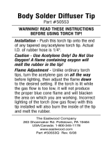
5-1. Equipment Included With The Kit
! Use only acetylene or propane gas
and oxygen with this equipment.
! Check valves are factory installed
on the torch handle. Do not remove
these components.
! The empty (unlabeled) cylinders
supplied with this kit must be ex-
changed for full cylinders through
your local welding gas distributor.
Filled cylinders will be properly
labeled. DOT regulations prohibit
the transportation of unlabeled cyl-
inders that contain hazardous sub-
stances. Follow the cylinder trans-
portation instructions supplied by
the gas distributor.
1 Grade T Oxy-Fuel Hose
2 MC Acetylene Cylinder (Empty)
3 Carrier
4 R Oxygen Cylinder (Empty)
5 Regulator − Oxygen (Green)
6 Cutting Tip
7 Cutting Attachment
8 Torch Handle
9 Check Valves
10 Welding/Brazing Tip
11 T-Handle (Two)
12 Tip Cleaner
13 Spark Lighter
14 Cylinder Key Wrench
15 Welding Goggles
16 Regulator − Fuel (Red)
1
2
3
4
5
7
891011121314
15
16
6
161-042
5-2. Specifications
Description
Fuel Gas
Cutting Capacity
Welding
Capacity
Eye Protection Hoses Cylinders
Warranty
Medium Duty
Oxy-Fuel
Cutting and
Welding
Equipment
Acetylene
Propane
(with Optional
Propane Tips)
Cuts Materials to
1/2 in. (12 mm)
Thickness with
Supplied Tips
Cuts Materials to
1-1/2 in. (38 cm)
Thickness with
Optional Tips
Welds Materials to
3/32 in. (2.4 mm)
Thickness with
Supplied Tips
Welds Materials to
3/16 in. (5 mm)
Thickness with
Optional Tips
Oxy-Fuel
Goggle
Flip Front
No. 5 Shade
2 x 4-1/4 in.
(51 x 108 mm)
Grade T
3/16 in. ID x
12.5 ft
(4.8 mm x
3.8 m)
20 ft
3
(566 L)
Type R
Oxygen
Cylinder
10 ft
3
(283 L)
Type MC
Acetylene
Cylinder
Two-Year
Limited

OM-254957 Page 6
5-3. Welding (Brazing) Tip And Gas Pressure Guide
Welding (Brazing) Tip Selection Guide
Hobart No. Victor No. Tip Size Material Thickness Fuel Gas Pressure Oxygen Pressure
−− Type 13 000 28 − 22 Gauge 3 − 5 psi (21 − 34 kPa) 3 − 5 psi (21 − 34 kPa)
−− Type 13 00 22 − 16 Gauge 3 − 5 psi (21 − 34 kPa) 3 − 5 psi (21 − 34 kPa)
−− Type 13 0 16 − 14 Gauge 3 − 5 psi (21 − 34 kPa) 3 − 5 psi (21 − 34 kPa)
5-4. Cutting Tip And Gas Pressure Guide
Cutting Tip Selection Guide
Hobart No. Victor No. Tip Size Material Thickness Fuel Gas Pressure Oxygen Pressure
−− 00-3-101 00 1/8 in. (3 mm) 2 psi (13 kPa) 25 psi (172 kPa)
770153 0-3-101 0 1/4 in. (6 mm) 2 psi (13 kPa) 25 psi (172 kPa)
770154 1-3-101 1 3/8 in. (10mm) 3 psi (21 kPa) 25 psi (172 kPa)
5-5. Victor-Compatible Components
Acetylene Regulators And Gauges
. All Gauges Feature Dual Scales (psi/kPa)
Hobart No. Description
770127 LP/Acetylene Low Pressure Gauge
770125 LP/Acetylene High Pressure Gauge
770622 Acetylene Regulator w/CGA-200 Connection
Oxygen Regulators And Gauges
. All Gauges Feature Dual Scales (psi/kPa)
Hobart No. Description
770503 Oxygen Regulator CGA-540
770128 Oxygen Low Pressure Gauge
770126 Oxygen High Pressure Gauge
Oxy-Acetylene Gas Welding Hose
. R-grade hose is for acetylene gas. T-grade hose is for all gases, including propane.
Hobart No. Description Grade Length Diameter
770130
Twin Welding Hose
R 25 ft (7.6 m) 3/16 in. (5 mm)
770132 R 25 ft (7.6 m) 1/4 in. (6 mm)
770133 R 50 ft (15.2 m) 1/4 in. (6 mm)
770131 T 25 ft (7.6 m) 1/4 in. (6 mm)
770515 R 100 ft (30.5 m) 1/4 in. (6 mm)
Acetylene Cutting Tips − 3-101
Hobart No. Size
770153 No. 0 − 3/8 in. (10 mm)
770154 No. 1 − 3/4 in. (19 mm)
Victor-Compatible Cutting Attachment
Hobart No. Description
770201 Medium Duty
Victor-Compatible Torch Handle
Hobart No. Description
770200 Medium Duty

OM-254957 Page 7
SECTION 6 − INSTALLATION
6-1. Installing Cylinders
! Install cylinders in an upright
position by securing to a
stationary support or cylinder
rack to prevent falling or tip-
ping. Maintain a clear path
from the cylinders to the work
area.
! Inspect equipment before
use. Do not use if grease or oil
is present on equipment or if
equipment is damaged. Have
equipment cleaned/repaired
by a qualified person.
! Do not slightly open or
“crack” fuel cylinder valve to
blow debris from the valve
outlet. Remove the debris us-
ing nitrogen, air, or a clean,
oil-free rag.
Remove the protective cap from the
cylinder valve.
Use nitrogen, air, or a clean oil-free
rag to remove dust or debris from
valve outlet. These particles can
damage regulators or cause a fire or
explosion.
161-019
Secure cylinders
to prevent falling
or tipping.
Notes

OM-254957 Page 8
6-2. Installing Regulators On Cylinders
! Use only acetylene or propane
gas and oxygen with this
equipment.
! Do not slightly open or
“crack” fuel cylinder valve to
blow debris from the valve
outlet. Remove the debris us-
ing nitrogen, air, or a clean
oil-free rag.
! Do not use pipe sealants on
metal to metal fittings, such as
hose and torch connections
and CGA cylinder con-
nections.
! Do not handle oxygen regulat-
ors with oily hands and never
apply oil to any part of an oxy-
gen regulator.
NOTICE − Do not use cylinder ad-
aptors to connect regulators to cylin-
ders. Regulators have CGA con-
nections (manufactured to stan-
dards of the Compressed Gas As-
sociation) which allow the regula-
tor to only be installed on the appro-
priate cylinder valve for the inten-
ded gas.
1 Oxygen Regulator
(Green Label)
2 Fuel Regulator
(Red Label)
Install the two-piece fitting of the
oxygen regulator (green) on the cor-
responding fitting on the oxygen
cylinder. The oxygen cylinder has
right-hand (clockwise) threads. Use
wrench to tighten hex nut.
Install the two-piece fitting of the fuel
regulator (red) on the fuel cylinder
(acetylene or propane only). The fuel
cylinder has right-hand (clockwise)
threads. Use wrench to tighten hex
nut.
. Contact the gas supplier if the
regulator fittings do not match
the cylinder fittings.
3 Working Pressure Gauge
4 Cylinder Pressure Gauge
Each regulator has two gauges. The
gauge closest to the cylinder shows
the pressure in the cylinder. The
other gauge shows the outlet pres-
sure going to the torch handle.
Tools Needed:
1
2
3
4
1 in.
161-028 / 044

OM-254957 Page 9
! Use only industrial grade hose.
Grade T hose (supplied with
kit) is acceptable for all fuel
gases including acetylene.
Grade R hose is for acetylene
only.
! Replace hoses at the first sign
of any defects, flaws, or dam-
age. The hoses should other-
wise be replaced every four
years. Inspect hoses for dam-
age or leaks before each opera-
tion. Do not allow hoses to
come in contact with hot metal,
molten solder, or corrosive
chemicals. Do not expose
hoses to fluxing agents as
these agents will deteriorate
the hose materials and cause
them to leak.
! Do not splice or use damaged
hoses.
! Do not use pipe sealants on
metal to metal fittings, such as
hose and torch connections
and CGA cylinder connections.
1 Regulator
2 Hose
3 Flow Adjustment Handle
Connect green hose to the regulator
on the oxygen cylinder. Connect red
hose to the regulator on the fuel gas
cylinder.
. The fuel fittings have left-handed
threads.
Use wrench to tighten fittings.
NOTICE − Before opening the cylin-
der valves, turn regulator adjusting
screws all the way out to release pres-
sure on the regulator diaphragm.
Pressure may damage the regulators.
Stand with the oxygen cylinder valve
between you and the regulator. Slowly
open the oxygen cylinder valve 1/4
turn until the tank pressure stabilizes,
then fully open the oxygen valve to
seat it in the open position.
Tighten the adjustment handle (on the
regulator adjustment screw) to bring
the pressure up to 5 psi (34 kPa). Al-
low oxygen to flow through hose for
about 10 seconds. Stop oxygen flow
by turning adjustment handle counter-
clockwise.
Stand with the fuel cylinder valve
between you and the regulator. Using
the supplied key wrench, slowly open
the fuel cylinder valve 1/4 turn until the
tank pressure stabilizes, then open
the fuel valve to a maximum of one full
turn (acetylene) or fully open (all other
fuel gases). Leave wrench on cylinder
so cylinder can be shut off quickly.
Tighten the adjustment handle (on the
regulator adjustment screw) to bring
the pressure up to 5 psi (34 kPa). Al-
low fuel gas to flow through hose for
about 10 seconds. Stop fuel gas flow
by turning adjustment handle counter-
clockwise.
Tools Needed:
6-3. Installing Hoses On Regulators
11/16 in.
1
2
3
161-030

OM-254957 Page 10
6-4. Attaching Hoses To Torch Check Valves
! Check valves are factory in-
stalled on the torch handle. Do
not remove these components.
! Do not use pipe sealants on
metal to metal fittings, such as
hose and torch connections
and CGA cylinder con-
nections.
. The hex nut on the fuel hose has
notches on the corners. The hex
nut corners are smooth on the
oxygen hose.
1 Torch Handle
2 Fuel Hose (Red)
3 Oxygen Hose (Green)
4 Check Valves
Attach fuel hose (red) to fuel inlet
fitting on torch flashback arrestor. The
nut on the fuel hose has left-hand
threads.
Attach oxygen hose (green) to oxy-
gen inlet fitting on torch flashback
arrestor. The nut on the oxygen hose
has right hand threads.
Use supplied wrench to tighten
connections.
Tools Needed:
11/16 in.
1
2
3
4
161-031
6-5. Attaching Cutting Attachment To Torch Handle
! Do not use cutting attach-
ment if the o-rings are miss-
ing or damaged.
! Do not use pipe sealants on
metal to metal fittings, such
as hose and torch connec-
tions and CGA cylinder con-
nections.
. See Section 6-7 for attaching
brazing tip to torch handle.
1 Cutting Attachment
2 Torch Handle
The cutting attachment uses two
o-rings to seal the connection to the
torch handle. If replacing the cutting
attachment, be sure the o-rings are
properly installed.
Attach cutting attachment to torch
handle.
Use wrench to tighten connections.
Tools Needed:
3/4 in.
1
2
161-032

OM-254957 Page 11
6-6. Installing Cutting Tip On Cutting Attachment
! Do not use pipe sealants on
metal to metal fittings, such
as hose and torch connec-
tions and CGA cylinder con-
nections.
NOTICE − Do not drop or mis-
handle the cutting tip or the seating
surface may be damaged.
Cutting tips are available in differ-
ent sizes to accommodate various
metal thicknesses. Use the table in
Section 5-4 to select the correct tip,
and to determine the correct fuel
and oxygen pressures.
Inspect cutting tips for damage and
to ensure that the cutting orifice and
preheat holes are not blocked with
dirt or slag.
. A No. 0 cutting tip is already in-
stalled in the cutting attach-
ment.
1 Cutting Tip
2 Cutting Attachment
Install correct cutting tip in cutting
attachment.
Use wrench to tighten connections.
Tools Needed:
1 2
1 in.
161-033
6-7. Attaching Welding/Brazing Tip To Torch Handle
! Do not use pipe sealants on
metal to metal fittings, such
as hose and torch connec-
tions and CGA cylinder con-
nections.
Welding/brazing tips are available
in different sizes to accommodate
various metal thicknesses. Use the
table in Section 5-4 to select the
correct tip, and to determine the
correct fuel and oxygen pressures.
. A No. 0 welding/brazing tip with
mixer is supplied with the kit.
1 Welding/Brazing Tip With
Mixer
2 Torch Handle
Attach welding/brazing tip to torch
handle.
Use wrench to tighten connections.
Tools Needed:
1
2
3/4 in.
161-034

OM-254957 Page 12
6-8. Testing The System For Leaks
! Leak test the system before
lighting the torch. Repeat
this procedure every time
the equipment is set up or a
cylinder is changed.
! Use an approved oil-free leak
detection fluid or leak detec-
tor to locate possible leaks.
! Do not stand in front of or be-
hind the regulator when
opening the cylinder valve.
Never open a cylinder valve
suddenly as this can damage
a regulator or cause an oxy-
gen regulator fire.
1 Fuel Regulator Adjustment
Handle
2 Oxygen Regulator Adjustment
Handle
3 Torch Handle Fuel Valve
4 Torch Handle Oxygen Valve
5 Oxygen Cylinder Valve
6 Acetylene Cylinder Valve
Turn the fuel and oxygen regulator
adjustment handles to the Off posi-
tion (counterclockwise).
Close the fuel and oxygen valves
on the torch handle.
Slowly open the oxygen cylinder
valve one turn and adjust pressure
to 20 psi (138 kPa) by turning
oxygen regulator adjustment
handle clockwise.
Using the supplied key wrench,
slowly open the fuel cylinder valve.
Adjust pressure to 10 psi (69 kPa)
by turning fuel regulator adjustment
handle clockwise.
Check every connection and joint
from the cylinder valve to the torch
tip with an approved oil−free leak
detection fluid or leak detector. If
leaks are detected, eliminate them
before proceeding. If leaks cannot
be eliminated, do not put the equip-
ment into service until it has been
repaired or replaced.
Close cylinder valves.
Tools Needed:
61
2
5
11/16, 3/4, 1 in.
43
. Check all fittings
and connections
for leaks.
161-013 / 031 / 036

OM-254957 Page 13
SECTION 7 − OPERATION
7-1. Purging Oxygen From The System And Adjusting Oxygen Pressure
! Inspect all equipment before
use. Do not use damaged,
defective, or improperly ad-
justed welding and cutting
equipment. Make sure levers
and valves work properly,
threads on equipment are
clean (no grease or oil) and
not deformed, gauges are in-
tact and easy to read, regu-
lator is clean and free of oil or
dirt, and fittings are properly
sized for the cylinder. Make
sure hoses are clean (no
grease or oil). Be sure all
connections are tight and
there are no leaks in the sys-
tem.
! Always purge gas from the
system before lighting torch
to prevent a possible
mixed-gas explosion. Purge
gas in a well ventilated area
and away from flame or
sparks.
. See Sections 5-4 and 5-3 for
oxygen and fuel pressure re-
commendations.
. Purge fuel from the system ac-
cording to Section 7-2.
Purging Oxygen And Setting
Pressure
1 Oxygen Cylinder Valve
2 Torch Handle Oxygen Valve
3 Preheat Oxygen Valve
4 Oxygen Regulator Adjustment
Handle
Slowly open the oxygen cylinder
valve until valve is fully open.
Open oxygen valve on torch 1/4
turn for five to ten seconds. (If using
welding attachment, also open pre-
heat oxygen valve.) While the oxy-
gen is flowing, turn the adjustment
handle on the oxygen regulator to
achieve the desired working pres-
sure.
Close the oxygen valve and the
preheat oxygen valve on the torch
handle.
Purge fuel from the system and
adjust fuel pressure according to
Section 7-2.
Tools Needed:
1
4
2
3
161−032 / 036

OM-254957 Page 14
7-2. Purging Fuel From The System And Adjusting Fuel Pressure
! Inspect all equipment before
use. Do not use damaged,
defective, or improperly ad-
justed welding and cutting
equipment. Make sure levers
and valves work properly,
threads on equipment are
clean (no grease or oil) and
not deformed, gauges are in-
tact and easy to read, regu-
lator is clean and free of oil or
dirt, and fittings are properly
sized for the cylinder. Make
sure hoses are clean (no
grease or oil). Be sure all
connections are tight and
there are no leaks in the sys-
tem.
! Always purge gas from the
system before lighting torch
to prevent a possible
mixed-gas explosion. Purge
gas in a well ventilated area
and away from flame or
sparks.
! Do not use acetylene above
15 psi (103 kPa) flowing.
. See Sections 5-3 and 5-4 for
oxygen and fuel pressure re-
commendations.
. Purge oxygen from the system
according to Section 7-1.
Purging Fuel Gas And Setting
Fuel Pressure
1 Fuel Cylinder Valve
2 Torch Handle Fuel Valve
3 Preheat Oxygen Valve
4 Fuel Regulator Adjustment
Handle
Using the supplied key wrench,
slowly open the fuel cylinder valve
one turn maximum (for acetylene).
Fully open fuel cylinder valve for all
other fuel gases.
Open fuel valve on torch 1/4 turn for
five to ten seconds. (If using weld-
ing attachment, also open preheat
oxygen valve.) While the fuel is
flowing, turn the adjustment handle
on the fuel regulator to achieve the
desired working pressure.
Close the fuel valve and the preheat
oxygen valve on the torch handle.
Tools Needed:
4
1
2
3
161-032 / 043

OM-254957 Page 15
7-3. Lighting, Operating, And Shutting Down The Cutting Torch
Tools Needed:
1
! Always purge gas from the system
before lighting torch to prevent a
possible mixed-gas explosion.
Purge gas in a well ventilated area
and away from flame or sparks. See
Sections 7-1 and 7-2.
! Do not use matches or a cigarette
lighter to ignite the gas.
. See Sections 5-4 and 5-3 for oxygen
and fuel pressure recommendations.
. See Sections 7-1 and 7-2 for informa-
tion on adjusting oxygen and fuel pres-
sure.
1 Spark Lighter
2 Oxygen Valve
3 Preheat Oxygen Valve
4 Fuel Valve
5 Cutting Lever
Lighting The Torch
Hold the spark lighter near the torch tip.
Slowly open the fuel valve on the torch
handle 1/4 turn and quickly squeeze the
spark lighter to light the flame.
Slowly open the oxygen valve on the torch
to the desired pressure.
Continue to open the fuel valve until the
black sooty smoke disappears and the
flame begins to move away from the tip.
! Failure to force a sufficient amount
of fuel gas through the tip will cause
the tip to overheat and may cause a
flashback or backfire.
Slowly open the preheat oxygen valve on
the cutting attachment; a white-hot feather
(flame) appears.
Slowly add oxygen until the feather begins
to disappear into the bright cone at the end
of the tip. This produces a neutral flame
(ratio of fuel to oxygen is 1:1).
Operating The Cutting Torch
Hold the torch tip about 1/4 in. (6 mm) from
the metal to be cut.
Heat the metal until it is bright red (about
1550 F or 843 C).
Slowly depress the cutting lever on the
cutting attachment. Let the oxygen stream
burn through the metal, then completely
depress the lever to begin the cutting
process.
When Finished Cutting
NOTICE − Shut down the torch in the cor-
rect sequence or the torch may be dam-
aged. Oxygen must be released from the
system first or residual fuel in the handle or
fuel hose may burn. Fuel cannot burn
without oxygen.
When finished cutting, release the cutting
lever. Close the oxygen preheat valve on
the torch handle first and then close the fuel
valve on the torch handle.
Turn valves at fuel and oxygen cylinders
clockwise to the closed position.
Open the fuel valve on the torch handle to
relieve pressure; both gauges on the fuel
regulator should indicate zero (0) pressure.
Close the fuel valve on the torch handle.
Turn fuel regulator adjustment handle coun-
terclockwise until there is no pressure on
the regulator diaphragm.
Open the preheat oxygen valve on the torch
handle to relieve pressure; both gauges on
the oxygen regulator should indicate zero
(0) pressure. Close the preheat oxygen
valve and oxygen valve on the torch
handle.
Turn oxygen regulator adjustment handle
counterclockwise until there is no pressure
on the regulator diaphragm.
Neutral Flame
Even mixture of fuel and oxygen
2
3 45
161-037 / 038

OM-254957 Page 16
7-4. Lighting And Using The Brazing Tip
! Always purge gas from the system
before lighting torch to prevent a
possible mixed-gas explosion.
Purge gas in a well ventilated area
and away from flame or sparks. See
Sections 7-1 and 7-2.
! Do not use matches or a cigarette
lighter to ignite the gas.
! Do not allow the flame to touch the
brazing tip or allow the brazing tip to
overheat.
. See Sections 5-3 and 5-4 for oxygen
and fuel pressure recommendations.
. See Sections 7-1 and 7-2 for informa-
tion on adjusting oxygen and fuel pres-
sure.
1 Spark Lighter
2 Oxygen Valve
3 Fuel Valve
Lighting The Torch
Hold the spark lighter near the torch tip.
Slowly open the fuel valve on the torch
handle about 1/8 turn and quickly squeeze
the spark lighter to light the flame.
Slowly open the oxygen valve on the torch
to neutralize the flame.
Open the fuel valve on the torch handle
another 1/8 turn and then increase the
oxygen to neutralize the flame.
Continue this procedure until the maximum
amount of fuel gas is used and the desired
flame is present.
When Finished Welding/Brazing
NOTICE − Shut down torch in correct se-
quence or the torch may be damaged.
Oxygen must be released from the system
first or residual fuel in the handle or fuel
hose may burn. Fuel cannot burn without
oxygen.
When finished welding/brazing, close the
oxygen valve on the torch handle first and
then close the fuel valve on the torch
handle.
Turn valves at fuel and oxygen cylinders
clockwise to the closed position.
Open the fuel valve on the torch handle to
relieve pressure; both gauges on the fuel
regulator should indicate zero (0) pressure.
Close the fuel valve on the torch handle.
Turn fuel regulator adjustment handle
counterclockwise until there is no pressure
on the regulator diaphragm.
Open the oxygen valve on the torch handle
to relieve pressure; both gauges on the
oxygen regulator should indicate zero (0)
pressure. Close the oxygen valve on the
torch handle.
Turn oxygen regulator adjustment handle
counterclockwise until there is no pressure
on the regulator diaphragm.
Tools Needed:
1
23
161-039 / 040

Warranty Questions?
Call
1-800-332-3281
7 AM − 5 PM CST
hobart_warr 2018-01
Service
You always get the fast,
reliable response you
need. Most replacement
parts can be in your
hands in 24 hours.
Support
Need fast answers to the
tough welding questions?
Contact your distributor or
call 1-800-332-3281. The
expertise of the distributor
and Hobart is there to
help you, every step of
the way.
Assistance
Visit the Hobart website:
www.HobartWelders.com
Effective January 1, 2018
Warranty applies to all Hobart welding equipment with a serial number preface of MJ or newer.
This limited warranty supersedes all previous Hobart warranties and is exclusive with
no other guarantees or warranties expressed or implied.
Hobart products are serviced by Hobart or Miller Authorized Service Agencies.
LIMITED WARRANTY − Subject to the terms and
conditions below, Miller Electric Mfg. LLC, dba Hobart
Welding Products, Appleton, Wisconsin, warrants to its
original retail purchaser that new Hobart equipment sold
after the effective date of this limited warranty is free of
defects in material and workmanship at the time it is
shipped. THIS WARRANTY IS EXPRESSLY IN LIEU OF
ALL OTHER WARRANTIES, EXPRESS OR IMPLIED,
INCLUDING THE WARRANTIES OF
MERCHANTABILITY AND FITNESS.
Within the warranty periods listed below, Hobart/Miller will
repair or replace any warranted parts or components that
fail due to such defects in material or workmanship.
Hobart/Miller must be notified in writing within thirty (30)
days of such defect or failure, at which time Hobart/Miller
will provide instructions on the warranty claim procedures
to be followed. If notification is submitted as an online
warranty claim, the claim must include a detailed
description of the fault and the troubleshooting steps taken
to identify failed components and the cause of their failure.
Hobart/Miller shall honor warranty claims on warranted
equipment listed below in the event of such a failure within
the warranty time periods. All warranty time periods start on
the delivery date of the equipment to the original retail
purchaser, and not to exceed twelve months after the
equipment is shipped to a North American distributor or
twelve months after the equipment is shipped to an
International distributor.
3 Years — Parts (No Labor)
* Oxy−Fuel Regulators
1 Year — Parts (No Labor)
(90 days for industrial use)
* Oxy−Fuel Torches
* Oxy−Fuel Replacement Gauges
Hobart’s warranty shall not apply to:
Equipment that has been modified by any party other
than Hobart/Miller, or equipment that has been
improperly installed, improperly operated or misused
based upon industry standards, or equipment which
has not had reasonable and necessary maintenance,
or equipment which has been used for operation
outside of the specifications for the equipment.
HOBART PRODUCTS ARE INTENDED FOR
COMMERCIAL AND INDUSTRIAL USERS TRAINED AND
EXPERIENCED IN THE USE AND MAINTENANCE OF
WELDING EQUIPMENT.
The exclusive remedies for warranty claims are, at
Hobart’s/Miller’s option, either: (1) repair; or (2)
replacement; or, if approved in writing by Hobart/Miller, (3)
the pre-approved cost of repair or replacement at an
authorized Hobart/Miller service station; or (4) payment of
or credit for the purchase price (less reasonable
depreciation based upon use). Products may not be
returned without Hobart’s/Miller’s written approval. Return
shipment shall be at customer’s risk and expense.
The above remedies are F.O.B. Appleton, WI, or
Hobart’s/Miller’s authorized service facility. Transportation
and freight are the customer’s responsibility. TO THE
EXTENT PERMITTED BY LAW, THE REMEDIES
HEREIN ARE THE SOLE AND EXCLUSIVE REMEDIES
REGARDLESS OF THE LEGAL THEORY. IN NO EVENT
SHALL MILLER BE LIABLE FOR DIRECT, INDIRECT,
SPECIAL, INCIDENTAL OR CONSEQUENTIAL
DAMAGES (INCLUDING LOSS OF PROFIT)
REGARDLESS OF THE LEGAL THEORY. ANY
WARRANTY NOT PROVIDED HEREIN AND ANY
IMPLIED WARRANTY, GUARANTY, OR
REPRESENTATION, INCLUDING ANY IMPLIED
WARRANTY OF MERCHANTABILITY OR FITNESS
FOR PARTICULAR PURPOSE, ARE EXCLUDED AND
DISCLAIMED BY HOBART/MILLER.
Some US states do not allow limiting the duration of an
implied warranty or the exclusion of certain damages, so
the above limitations may not apply to you. This warranty
provides specific legal rights, and other rights may be
available depending on your state. In Canada, some
provinces provide additional warranties or remedies, and
to the extent the law prohibits their waiver, the limitations
set out above may not apply. This Limited Warranty
provides specific legal rights, and other rights may be
available, but may vary by province.
Hobart oxyfuel_warr 2018−01

Resources Available
Always provide Model Name and Serial/Style Number.
To locate a Service Center:
Call 1-800-332-3281
or visit our website at www.HobartWelders.com/wheretobuy
For Technical Assistance:
Call 1-800-332-3281
7 AM to 5 PM CST − Monday through Friday
ORIGINAL INSTRUCTIONS − PRINTED IN USA 2018 Miller Electric Mfg. LLC 2018-01
Miller Electric Mfg. LLC
An Illinois Tool Works Company
1635 West Spencer Street
Appleton, WI 54914 USA
For Assistance:
Call 1-800-332-3281
Model Name Serial/Style Number
Purchase Date (Date which equipment was delivered to original customer.)
Distributor
Address
City
State Zip
Please complete and retain with your personal records.
Owner’s Record
Thank you for purchasing Hobart. Our trained technical support team is
dedicated to your satisfaction. For questions regarding performance, op-
eration, or service, contact us!
/