Page is loading ...

bre
network
Developer Guide
Version 7.1 – August 2018
How to build a

2.
Home
wiring
5.
Multi dwelling
Units (MDUs)
8.
Modular jointing
chambers –
Quadbox
TM
3.
Developer
self-install
6.
Commercial
units
11.
Health and
safety advice
9.
Joint boxes,
footways and
frames & covers
4.
Cabling
and ONT
positioning
7.
Duct laying
10.
List of
abbreviations
and acronyms
CON
TENTS
1.
Internal
equipment
12.
Quality control
checklist

3
Internal equipment
1
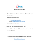
The ONT is the Openreach demarcation point.
It replaces the traditional copper master socket.
The Openreach ONT sits in an enclosure along with
the Battery Backup Unit (BBU) and associated wiring,
keeping everything neat and tidy. The enclosure is
designed for simple wall mounting with just 2 screws.
• Optical port connects to the external
Customer Splice Point.
• Ethernet port connects to the
communications provider's (CP) router.
• Telephony port connects to voice network.
Openreach Optical Network
Termination (ONT) and enclosure
254mm
215mm
Battery Backup Unit (BBU)
The BBU sits in the enclosure along with the ONT. It supports
voice calls for approximately an hour should there be any
interruption to the mains power supply.
A red warning light will ash when a replacement battery is
required. Openreach warranties the battery for 90 days, where
it then becomes the responsibility of the home owner.
How to build a fibre network - version 7.1

4
Openreach: Developer Guide
Internal equipment
Legacy ONT
The legacy ONT was the previous piece of
equipment used before the introduction of the
1+1 in January 2018.
This ONT is mounted directly to the wall and has
no associated enclosure.
• Optical port connects to the external
Customer Splice Point.
• Ethernet ports connect to the CP router.
• Telephony ports connect to voice network.
155mm
195mm
Optical
port
Ethernet
ports
Telephony
ports
The CSP houses
the external
connectorised
bre cable and
the connected end
that ts into the
ONT. The CSP sits
of the outside of
the house.
Where you self-install there will be no internal
CSP, instead the connectorised cable will plug
directly into the ONT. If the connectorised
cable end is damaged during installation
then an internal CSP may be required to be
tted to complete installation. This will be
undertaken at the commissioning stage by
Openreach. Your Field Based Co-ordinator
(FBC) will guide you through this.
BBU
The battery backup
supports voice calls
for approximately
one hour should
there be any
interruption to the
mains power supply.
A red warning light
will ash when
a replacement
battery is required.
Openreach
warranties the battery
for 90 days, where
it then becomes the
responsibility of
the home owner.
Customer Splice Point (CSP)

5
The wiring that you install in your customer’s
properties is pivotal to their experience.
Your options in the installation
of internal wiring are shown
as below
Implications of locating the service
provider’s router in a cupboard
It is important to note that the Wi-Fi service
your customer receives is dependent upon
the intended location of the communication
provider’s router. Placing the router in a
service cupboard or under stairs cupboard will
signicantly reduce the speed and coverage
your customer will receive.
It is highly recommended that if you position
the router in this way that you provide additional
RJ45 ports within the home. Ideally for optimum
speeds to be enjoyed using Wi-Fi service it
is recommended that you locate the router
centrally within the property.
For information, advice and guidance around
positioning, please refer to: PAS: 2016 Next
Generation Access for new Build Homes Guide.
All internal wires and sockets beyond the
ONT are the responsibility of the developer/
future home owner.
If any part of the connectorised internal
bre cable is found to be damaged at
commissioning, it is the developer’s
responsibility to replace it.
If the homeowner experiences a lack of
service or poor service, which is due to
a fault within the internal installation
of wiring, which requires Openreach to
rectify, the homeowner will be charged.
Please note
Home wiring
2
How to build a fibre network - version 7.1

6
Openreach: Developer Guide
The simple install
The simplest installation will be the provision of the Openreach equipment
(i.e. the ONT will be positioned adjacent to the outside wall) to which the customer
then attaches the router, provided by their communications provider. Without
internal data cabling, this relies on wireless extenders using.
the homes electricity cabling system to provide internet connection to other rooms in
the house. Power sockets should be provided for the Openreach equipment and for the
communications provider’s router and for the wireless extenders / adaptors if used.
CSP: Customer Splice Point
ONT: Optical Network Termination
BBU: Battery Backup Unit
Option 1
Connectorised bre cable
Voice cable
Ethernet cable
Home wiring
External
Internal

7
Option 2
Relocating the ONT and BBU
Some developers want to position the v and Battery Backup Unit (BBU) further
inside the property. This will require a longer connectorised internal bre
cable which is recommended to be installed in a protective conduit to the
external Customer Splice Point (CSP) plus the provision of a power socket for
the equipment. Additional Cat6* cabling is required for this option from the
ONT & BBU to connections in the study and living room. These connections
should terminate in an RJ45 socket. A power socket should be provided for the
communications provider’s router, if the router is placed near the RJ45 socket
or a double socket if it is placed by the ONT and BBU.
*Cat6 is the preferred option to ‘future proof’ for modern devices
CSP: Customer Splice Point
ONT: Optical Network Termination
BBU: Battery Backup Unit
Connectorised bre cable
Voice cable
Ethernet cable
Home wiring
How to build a fibre network - version 7.1

8
Openreach: Developer Guide
As per option 2 this extends the number of xed sockets so that the home owner doesn’t
need to rely on wireless connections in the majority of the house. This would enable the
down-streaming of 4K television in those areas where the customer is most likely to use
high bandwidth applications like streaming TV, gaming consoles or video conferencing.
One double power socket should be provided for the Openreach equipment and for the
communications provider’s router. We recommend that all the data cabling from the
rooms are terminated in a data patch panel (example as below) in close proximity to
the ONT to facilitate easy connection.
It is also recommended that where an aerial socket is provided for televisions that
an ethernet data socket and associated wiring is also provided.
CSP: Customer Splice Point
ONT: Optical Network Termination
BBU: Battery Backup Unit
Connectorised bre cable
Voice cable
Ethernet cable
Relocating the ONT and BBU and
adding data points in multiple rooms
Home wiring
Option 3

9
Home wiring
The networked home
This option offers data cabling from wherever the Openreach ONT & BBU equipment is located,
to all rooms in the home using a home wiring patch panel and RJ45 data sockets throughout.
This could be offered either as standard or a customer paid option and will guarantee the best
customer experience and help differentiate your property.
We recommend that all the data cabling from the rooms are terminated in a data patch panel
in close proximity to the ONT (Optical Network Termination) or the communications provider’s
router to facilitate easy
connection.
Option 4
CSP: Customer Splice Point
ONT: Optical Network Termination
BBU: Battery Backup Unit
Connectorised bre cable
Voice cable
Ethernet cable
How to build a fibre network - version 7.1

10
Openreach: Developer Guide
Home wiring
When Openreach install the equipment we will
install the ONT wherever the incoming bre cable
is located. Where you self-install the ONT, you will
have control over when the equipment is installed.
The ONT will remain the property of Openreach in
both installation scenarios.
Where you are self-installing the Openreach
equipment we will supply the ONT, along with the
battery back-up and the connectorised internal
bre cable you need. If you are installing the ONT
opposite the cable entry hole, you will need to install
a ush mounted double back box on the internal
wall where the ONT is to be located.
The ONT will be installed at this location unless an
alternative position has been agreed with your FBC
and the appropriate connectorised internal bre
cable run in a continuous fault-free length to the
alternative position.
While the provision of internal wiring beyond
the Openreach ONT is the responsibility of
the developer, you can contract an Openreach
engineer to do this work for you. If interested,
please contact your local customer network
solutions team on 0800 783 2023. Terms
and Conditions for the provision of internal
wiring will apply.
Provision of the Openreach equipment
Voice Cabling
• Voice extension cabling shall run direct from
the ONT voice port. Connection to the ONT
is made via a BS6312 431A Plug inserted
into voice port 1. This socket must be a slave
socket, not a master socket.
• Extension sockets shall be located close to
power sockets for easy equipment connection.
A minimum of 50mm between telephone
cables and power cables shall be left
throughout.
• Where this isn’t practical, telephone and power
cables must be separated by an acceptable
divider (i.e. of rigid, non-conducting material).
• Extension wiring must be telephone/data
grade and have plain annealed solid copper
conductors of a diameter between 0.5mm and
0.63mm. The conductors shall be in twisted
pair format. The conductor resistance shall
be of a maximum of 96 ohms/km. The cable
sheath shall be PVC.
Data Cabling
• As a rule of thumb connectorised internal
bre cables shall not exceed the minimum
bend radius (i.e. no smaller than) of a £2 coin.
• Detailed information on cable installation and
separation is given in the British Standards.
• Code of Practice 6701, Part 1 (particularly
clause 6) and the relevant sections of the
latest IEE Regulations for electrical Installation
(Regulation 525 is of particular importance).
• The wiring pattern for cabling must be either
in series or spur. For data it must be point to
point as speeds will be impacted after the rst
point of a daisy chain.
• We’d recommend data cabling rooms
likely to benet most from a physical
connection, like the room with the main
TV and the home ofce.
Please note: If connectorised cable is damaged by developers during installation then an
internal Splice Point may be required to be tted to complete installation. This will be undertaken
at commissioning stage by Openreach.
Installation of internal cabling
How to build a fibre network - version 7.1

11
• Fit the double electrical socket to the wall.
• Fit the double back box to the wall.
• Fit the slave voice socket to the wall (can be modular to house one voice port and one data port).
• Fit RJ45 modular boxes. The number of these are to be determined by you the developer
Openreach recommend a minimum of two are tted, one for the communications provider
router and the other to the room requiring streaming media for example for streaming
high denition TV. See the internal wiring section for further information.
• All internal wiring to be run back to this point (daisy chain for voice and point to point for data).
• See below for the recommended layout of sockets on the wall, the layout can be mirrored.
Internal Work at dened ONT and Communications
Provider router position
Single Dwelling Unit at second
x (Internal Work)
• Fit the enclosure to the wall over the double back
box using the supplied template.
• Take the pre-connectorised cable from back box to
the ONT position.
• Connect the BBU to the ONT power port.
• Clean both the pre-connectorised cable and the
optical port of the ONT before inserting the cable.
A video showing the installation
of the internal equipment can be
found on the Openreach developer
website at the following link:
https://www.ournetwork.
openreach.co.uk/property-
developers/developer-handbooks-
and-extra-services.aspx
Developer self-install
3
How to build a fibre network - version 7.1

12
Openreach: Developer Guide
Remove the cap from the green bre
connector and use the One Click cleaner to
clean both the connector and the optical
port on the ONT. Once cleaned plug into
the Optical port on the ONT. Care must be
taken at this stage not to contaminate the
end of the bre connector to avoid any dirt
from inhibiting the data signal.
Open the green ap on the Optical port and
insert the bre cable. The cable is designed
to t only one way, so ensure the raised
nodule is facing the wall when inserting.
• Connect the alarm lead between the RJ45 socket on the BBU and the BBU port on the ONT.
• Connect the ethernet cable to the PORT 1 port on the ONT. The other end of this cable will be
connected to the CP router once ordered.
• Connect the telephone cable to the TEL 1 port on the ONT and plug into the Slave socket on the
wall (this cable is a separate item and will be provided by your FBC).
• Connect the mains
adaptor to the BBU
and plug into the mains
socket.
• You can see the nal
layout and cable
connections here,
ensure the cable lengths
are correctly positioned
within the enclosure
before continuing.
Developer self-install
Fujikura are our chosen producer of
bre cleaners. The One Click cleaner
shown here can be found at the
following link:
www.fujikura.co.uk/products/bre-
and-optical-devices/connectivity-
and-cleaning/one-click-cleaners/
Please note

13
Developer self-install
• Once plot is complete contact your Openreach FBC
as each plot is ready for connection (i.e. front door
on; power on, ONT area decorated).
• Your Openreach FBC will then raise a job with the
Openreach teams to commission the plot(s).
DSI next steps
How to build a fibre network - version 7.1

14
Openreach: Developer Guide
For Single Dwelling Units a pre-connectorised
cable will be available in different lengths
(5m, 20m, 30m, 50m and 100m) and will come in
individual bags that can be ordered via the FBC.
A minimum length of 2m of excess cable will be
left coiled externally for ease of installation.
Once the pre-connectorised cable is
installed then Openreach (or their third party)
will visit to terminate the pre-connectorised
cable at the external CSP location back to the
serving Splitter location(s) and then commission
the plot.
Single dwelling units
Run the pre-connectorised cable from
agreed ONT position back to external
Customer Splicing Point (CSP).
The bend radius of cable must meet
all necessary installation requirements
i.e. no 90 degree bends.
Coil 1m of pre-connectorised cable
into the empty double back box, taking
care not to damage the connectorised
end and t blanking plate to help
protect bre.
Ensure the green caps on the end of the
connectorised internal bre cable are
kept on during construction to avoid
damage to the bre cable.
Installation of pre-connectorised
cable at rst x (Internal Work)
Step 1
Step 2
Cabling and ONT positioning
4

15
Complying with
Building regulations
Even where you are not working with
Openreach or another infrastructure
company to provide a functioning
broadband and phone infrastructure
to the home the Part R regulations
require the provision of duct in the
default position discussed below so
that infrastructure can be installed
in the future.
ONT in the
default position
When the ONT is to be tted in the
default position on an internal wall
directly opposite the entry position
of the service access hole adjacent to
the external duct location, external
capping will be tted on completion.
To keep things tidy, make sure that
the service access hole is drilled in line
with the duct and in keeping with the
dimensions shown below.
The service will be sealed with a
grommet or mastic before tting
the CSP.
All internal wires and
sockets beyond the Optical
Network Terminal (ONT)
are the responsibility of the
developer/future home owner.
Any faults or defects resulting
in an Openreach visit may
incur a charge.
Please note
External presentation by developer
External capping tted by Openreach
Cabling and ONT positioning
How to build a fibre network - version 7.1

16
Openreach: Developer Guide
Cabling and ONT positioning
Wherever possible, the duct shall be positioned
on the opposite side of the wall to where the ONT
will be installed, removing the need to run internal
bre cables. However, there are cases where the
kit will need to be installed away from the external
lead in and your FBC will be able to advise.
When Openreach is to install the Openreach ONT, battery
backup and external customer splice point, two metres of
cable is required at external end and 1m (or 2m for non-
connectorised cable) at the internal point of the installation.
It shall be left coiled and housed/protected within a
ush mounted double back box and faceplate ready for
Openreach provision of ONT and BB.
ONT installed inside the house (non-default position)
When the ONT is to be tted in a non-default
position i.e. not directly behind the external
CSP, such as in a utility cupboard, the above
guidelines shall be followed to provide entry of
the cable into the home.
What will be different will be the length of cable
that will run from the entry point into the building
to the Openreach ONT. In this case you have
the responsibility of running the connectorised
internal bre cable required inside the house in
such a way that it is undamaged and complies
with building regulations for the installation of
telecommunications infrastructure cabling.
The same rules apply to the running of bre
cable internally that are specied in the section
on exterior ducting. For example, the installation
of the bre cable in protective conduit and the
absence of a bend more than 90°.
Once installed the ONT and BBU need to
be kept powered on.
If this option is followed but the cable is found
to be damaged once in situ, either during
installation, damage sustained by construction
work inside the property, or damage subsequent
to the home owner occupying the property,
then unless you at your expense opt to replace
the damaged bre cable during commissioning
of the property, then Openreach will install
the equipment in the default location within
the home using surface mounted cables and
charge accordingly.
The developer must run the connectorised
internal bre cable in a continuous length and it
must remain free from any damage that could
reduce the lifespan of the cable.
Interconnecting voice lead (Item Code
077004) will be provided free of charge
by Openreach. It provides connectivity
from the ONT to a co-located voice
socket/patch panel. On installation
it becomes the property of the home
owner. Alternatively, the developer may
choose to hardwire directly into a voice
socket using a 431A Plug.

17
Cabling and ONT positioning
When Openreach is to install the Openreach ONT,
battery backup and external customer splice point,
two metres of cable is required at external end of
the installation and 1m internally.
It shall be left coiled and housed/protected within
a ush mounted double back box and faceplate
(or could be a brushed faceplate if preferred)
ready for Openreach provision of external CSP
and ONT nearby.
When the developer is installing the Openreach ONT
and battery backup 2m of cable is required at the
external Splice Point and 1m at the ONT location.
Ensuring re safety with internal cabling
Once ductwork and cable has been run from communications
room to splitter – contact FBC to gain conrmation that all
cables are run correctly.
FBC will then raise a job with the Openreach Internal teams to
commission the splitter(s). Once commissioning is complete
contact FBC as each plot is ready for connection (front door
on power on, ONT location is decorated).
FBC will then raise a job with the Openreach internal teams
to commission the plot(s).
Multiple Dwelling Unit (external)
• Fit all external duct from the site connection
point to the building entry position.
• Fit all tray work from the building entry position
to and up the risers to the internal splitter
position(s).
• Run the bre cable from the splitter location to
(and in) the riser to the communications room.
• Coil a minimum of 2m in the communications
room.
• Coil a minimum of 2m at internal splitter
position.
• Ensuring bend radius of cable must meet all
necessary installation requirements i.e. no 90
degree bends (as per current copper process).
• If there is a comms room it has to be within
2m at point of entry.
• If the risers are away from the point of entry
but is fed through a vented car park then the
external cable can be fed on tray work.
• If the risers are away from point of entry and is
fed through a non-vented car park then an area
needs to be allowed within 2m of point of entry
to change from external to internal cable.
Multiple Dwelling Unit – Next Steps
• Once ductwork and cable has been run from
communications room to splitter – contact
FBC to gain conrmation that all cables are
run correctly.
• FBC will then raise a job with the Openreach
Internal teams to commission the splitter(s).
• Once commissioning is complete contact
FBC as each plot is ready for connection
(front door on power on, ONT location is
decorated).
• FBC will then raise a job with the Openreach
internal teams to commission the plot(s).
Fire stopping
compartment
penetrations
All holes drilled through oors and
re compartment walls must be
re proofed using correct materials
to prevent the spread of smoke
in the event of a re. Openreach
can provide these materials
in either cartridge (similar to
silicone sealant) or putty form.
How to build a fibre network - version 7.1

18
Openreach: Developer Guide
Cabling and ONT positioning
Issues with home wiring
• Connectorised bre cable too short,
cut or damaged.
• Defective or damaged home wiring
creating a fault on the line.
• Extension sockets not connected to
Openreach ONT.
• Bending radii exceeded causing reduced
levels of service due to bre being broken
or the bend was too tight.
• Incorrect cable type or wiring
conguration
Impact on delivery
• Inability for Openreach to provide service
and developer requirement to re-provide
connectorised bre cable.
• Poor user experience for home purchaser
with possibility of Openreach charges if
called upon to rectify.
• Slower data download speeds
experienced.
• Limit duct runs to a depth of 350mm on
footway, 450mm on soft ground or 600mm
if shared carriageway surface at house end.
• The Openreach duct shall be no greater than
15mm from the nished wall surface.
• The duct shall protrude no more 50mm from
the nished ground level.
• A draw rope must be installed between the
joint box and the duct at the property wall.
• The duct opening must be covered,
preventing the ingress of debris.
• Ducting from property to the footway boxes
shall be laid 4-6 weeks before the plots are
handed over.
Fixing cables securely
If you’re running any cables through a re protected
area like a re escape route, escape staircase or
walkway, the cable must be adequately secured
using non-combustible xings. Wiring regulations
must be followed, ensuring that wiring systems
in escape routes are supported in such a way that
they will not be liable to premature collapse in
the event of re. This applies to all cabling and
not just electrical cables e.g. alarm, telecoms and
control wiring. From January 2019 this will apply
throughout the installation as the 18th Edition
wiring regulations come into force.
Typical issues with duct
presentation
• Duct not cut to the appropriate height
from the nished ground level.
• Duct installed too shallow.
• Duct protruding too far from the nished
wall surface.
• Duct not lining up with internal bre
cable lead in.
Impact on delivery of issues
• Delay in completion – Openreach may refuse
to cable if we can’t guarantee adequate
protection.
• The capping and covers would look unsightly.
• Failure to provide conduit can prevent a cable
from being installed.
• Customers may not be able to place orders
and remedial work may incur additional costs.

19
Small MDUs (12 or less units)
Openreach will create a bre layout based on
your Mechanical & Electrical (M&E) drawings
(on larger MDUs) of the MDU. The design
will calculate the stores required to build
the network.
Your FBC is on hand to guide you through the
ordering process to make sure the equipment is
available when you need it.
The incoming Duct 54zv and bre cable will
terminate in the communications intake room
or riser cupboard. This needs to be a secure and
safe location with access for installation and any
future maintenance visits.
Our bre box/splitter needs to be installed at
a minimum height of 200mm and a maximum
of 1500mm. Your FBC will agree the location
with you.
Connectorised internal bre cable needs to be
run from each plot to the bre DP location.
A minimum of 3m of coiled cable needs to be left
at the bre DP, with 1m left at the plot end.
A wayleave may be required from the building
owner prior to installing apparatus in common
areas. Remember you may need to order
copper, for example: for lift lines.
Multi Dwelling Units (MDUs)
5
How to build a fibre network - version 7.1

20
Openreach: Developer Guide
Large MDUs (more than 12 units)
For larger MDUs there may be a
requirement to install multiple bre
boxes/splitters.
405mm
These boxes/splitters will be connected with
Duct 54 and bre cable commonly housed
within the riser space.
330mm
120mm
Array of ports for internal bre cable
located at bottom of bre DP/splitter
Multi Dwelling Units (MDUs)
/