
INSTALLATION, USE
AND MAINTENANCE
Gas fryers Serie 700
2859251
2859171
2859271

1/199
Data Plate & Table of gas types p. 2
General Warnings
Normes et Directives
Installation and Gas &
Electric connection
General Warnings for the
Maintenance
Gas Ranges
Gas Griddle Plates
Gas Fryers
Gas Pasta Cookers
Lavastone Grills
Gas Bratt Pans
Cooking equipment Series 700

2/199
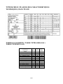
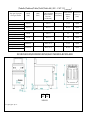
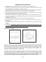
TYPENSCHILD \ PLAQUES DES CARACTERISTIQUES
TECHNIQUES \ DATA PLATE
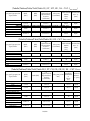
TABELLE GASARTEN / TABLE TYPES DES GAZ /
TABLE TYPES OF GAS
Type gaz/
Type of gas/
Gasart
P
n
[mbar]
P
min
[mbar]
P
MAX
[mbar]
G20 (Methane) (2H)
20
17
25
G25 (Methane) (2ELL)
20
17
25
G25 (Methane) (2E+)
25
20
30
G25.1 (Methane) (2HS)
25
20
30
G25.3 (Methane) (2EK)
25
20
30
G30 (Butane) (3B/P)
28-30
25
35
G30 (Butane) (3+)
28-30
20
35
G30 (Butane) (3B/P)
50
42,5
57,5
G31 (Propane) (3B/P)
28-30
25
35
G31 (Propane) (3P, 3+)
37
25
45
G31 (Propane) (3B/P)
50
42,5
57,5
G110 (Town gas) (1a)
8
6
15
G120 (Town gas) (1ab)
8
6
15

19/199
GENERAL WARNINGS
Read the instructions carefully before installation, use and maintenance of the appliance.
The installation has to be performed by qualified personnel following the manufacturer’s
instructions given in the provided manual.
The appliance is only suitable for the preparation and cooking of food in industrial kitchens
such as those used in restaurants, hospitals, company canteens, cooking centres, butcher’s
shops and food production firms. Any other type of use is not in accordance with the intended
purpose and could place people and/or objects at risk.
The appliance should only be used by trained personnel and for the use for which it was
designed.
Due to the nature of the appliance, the temperatures required for cooking may cause various
areas of the panelling, as well as kitchenware, to become hot. This is not a construction defect,
but a physical phenomenon caused by the chemical and physical properties of the materials
used for the construction of the appliances.
In the event of breakdown or malfunction, switch off the appliance and seek help exclusively
from an authorized technical assistance centre.
Only use genuine spare parts; otherwise no liability is assumed by the manufacturer.
The appliance must not be washed with high pressure water sprays and the vents or
inlets/outlets for air, fumes and heat must not be obstructed.
Children should be supervised to ensure they do not play with the appliance.
Before connecting the device make sure that the plate specifications correspond to the electrical
and gas supply.
When cooking, avoid placing pots and pans and/or crockery on the hotplate that could partially
cover the stainless steel part of the hob, otherwise the worktop may overheat.
When not in use, make sure the appliance is disconnected from the electric mains.
ATTENTION! The manufacturer declines any liability for damage caused by wrong
installation, tampering, making unauthorized changes, improper use, poor maintenance,
installation of non-original spare parts, not observing local norms, incorrect use or not
observing the instructions in this booklet.
For the installer
The functioning of the appliance has to be explained and shown to the user. After ensuring that
everything is clear, the instruction booklet has to be handed over to the user.
The user has to be informed that any building modification or restructuring that may in any way
modify the air supply necessary for combustion makes it necessary to carry out another check of
the functionality of the appliance. In particular, every variation (additional power) in the
appliances in the room may modify the balance of the gas supply in the room. That means that
appliances may be fed with gas at lower gas pressure and rate than those provided for and they
may give worse performance.
TECHNICAL FEATURES
The following instructions for set up and functioning refer to gas and mixed appliances belonging to
categories I
2H,
I
3P,
I
3B/P
, II
HS3B/P,
II
2E3PB/P
II
2H3+
, II
2H3B/P
,
with a power pressure for Butane/Propane
(G30-G31) of 30/50 mbar and Methane (G20) of 20 mbar. The DATA PLATE showing all the
appliance information is to be found inside the right or left side of the control panel, depending on
the model.

20/199
The appliances have been checked in accordance with the European directives down below:
2014/35/UE - Low Tension (LVD)
2014/30/UE - Electromagnetic Compatibility (EMC)
2016/426/UE - Gas Appliances (GAR)
2006/42/EC - Machinery directive
2011/65/CE - Rohs
1935/2004/UE - Food Contact Material (MOCA)
SVGW Directive G1 Directive for the installation of methane gas appliances in buildings
SVGW Norms L1 Norms for the installation of liquid gas appliances for home, professional use
and industry
SVGW Regulation of cantonal applications in Switzerland (for ex. fireproof regulations)
And the particular reference norms.
Declaration of compliance
The manufacturer declares that the appliances of their production meet the above mentioned EEC
directives and requires that installation be done observing the norms in force, particularly regarding
the system for letting out fumes and air exchange.
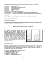
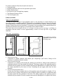
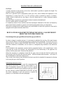
PROVISIONS FOR INSTALLATION
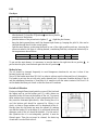
Place
It is advisable to install the appliance in a well-
ventilated room or under an extractor hood. The
appliance may be installed as a single unit or together
with others. In both cases, if it is installed near a wall of
inflammable material, a minimum distance according
the series (see figure) from the side and back walls must
be observed. In the event that it is not possible to
observe this distance, protective measures must be
taken (e.g. use of sheets of refractory material) which
ensure that the temperature of the walls is within the
established safety limits.
Norms and provisions
Installation operations, gas or voltage conversions to other than the original, starting up the
installation or appliance, ventilation, letting out fumes, and maintenance have to be done by
qualified personnel following the manufacturer's instructions, observing the norms in force and in
compliance with the following provisions (GB):
Gas Safety (Installation and Use) Regulations, 1984
Health and Safety at Work Act, 1974
Codes of Practice, BS6173, 1982
The Building Regulations, 1985
The Building Standards Regulations, 1981

21/199
For others countries follow the relevant local rules for:
Gas board rules
Building regulations and local fire prevention provisions
Safety norms in force
Provisions of the Gas supplying company
The Electrical Norms in force
The Fire Brigade rules.
Fumes evacuation
Type "A1" gas appliances
The deep fat fryers are type A1 gas appliances and it is not necessary to connect directly to an
evacuation pipe for combustion products. The products of combustion, however, have to be directed
into suitable hoods or similar devices, connected to a reliably efficient chimney, otherwise directly
outside. if these devices are not available, it is possible to use an extractor fan connected directly to
external environment with a capacity no lower than what is stated in table 1.
This value has to be increased with the air exchange necessary for the operators’ well-being in
accordance with the norms in force (approximately a total of 35 m
3
/h per KW of gas output
installed).
Type “B21” gas appliance
These appliances must be
connected in one of the
following ways:
Natural evacuation
Connection to reliable chimney with natural pull, interposing a pull device, letting out the
products of combustion directly outside.
Direct forced evacuation
Connection to a chimney with forced pull, putting in a pull device, letting out the products of
combustion directly into the external environment. The energy supply to the appliance must be
controlled by the system of forced evacuation and must be interrupted if its capacity falls below
the values prescribed by the norms in force. Restarting the gas supply must only be done
manually.
Forced evacuation under hood
In this case, the fume evacuation device of the appliance must be brought to a height of 1.8 m
from floor level, and the outlet section of the evacuation pipes for products of combustion must
be placed inside the base perimeter of the hood. The energy supply to the appliance must be
controlled by the system of forced evacuation and must be interrupted if its capacity falls below

22/199
the values prescribed by the norms in force. Restarting the gas supply must only be done
manually.
INSTALLATION
Preliminary operations
Remove the appliance from the packaging, ensure that it is intact and, if in doubt, do not use it but
contact professionally qualified personnel. The packaging materials are compliant with
environmental safety regulations. They can be stored without risk, or else should be disposed of in
accordance with current national regulations, particularly those regarding the nylon bag and the
polystyrene.
After verifying that the appliance is in good conditions, the protective film may be removed. Clean
the external parts of the appliance carefully with warm water and detergent, using a cloth to remove
all remaining residues and then dry it with a soft cloth. If there are still traces of glue, these can be
removed using a suitable solvent (e.g. acetone). Under no circumstances should abrasive substances
be used. After the installation the appliance should be levelled by lowering or raising the adjustable
legs.
Gas Connection
Before connecting the appliance, it is necessary to check that the type of gas available corresponds
to the type of gas the appliance has been set for. In the event that they do not correspond, it is
necessary to proceed as described in the paragraph Functioning with a gas type different from the
type provided for. The connection to the screwed pipe joints, which have a diameter of ½ inch and
are situated on the appliance bottom, may be fixed or mobile by using a fitting quick-coupler. If
flexible piping is used, it has to be made of stainless steel and meet the regulations in force. All the
seals on the junction threads have to be made of materials certified for gas use. In order to ensure a
quick interruption of the gas supply, before setting up each single appliance, it is necessary to install
a cut-off cock; the device has to be placed in an easily accessible position so that it is possible to
turn off the gas supply when the appliance is not used. After completing the connection, the
tightness of the cut-off cock has to be checked by using a leak-finder spray.
Electric connection
Before connecting the appliance, it is necessary to check that the voltage of the available power
supply corresponds to the voltage the appliance has been set for. If they do not correspond, it is
necessary to modify the connection as shown in the electric diagram, if voltage change is provided
for. The junction box is situated behind the control panel of the top and it is made accessible by
unscrewing the screws that fix the panel, removing it and taking out the junction box.
Furthermore, it is necessary to check that the earthing wire is efficient, that the earth conductor on
the connecting side is longer than the other conductors, that the connecting cable has a wire bunch
adequate for the power absorbed by the appliance, and that the connecting cable is at least type H07
RN-F. It is necessary to run the cable first through the cable gland. If the supply cord is damaged,
it must be replaced by the manufacturer service agent or similarly qualified persons in order to
avoid a hazard. As in international provisions, before setting up the appliance a unipolar
device has to be installed with a contact opening of at least 3 mm that must not interrupt the
YELLOW-GREEN earthing wire. This device has to be installed near the appliance, has to be
approved, and has to have adequate capacity for the absorption of the appliance (see
table TECHNICAL FEATURES).
The appliance has to be connected to the EQUIPOTENTIAL system. The connector is
situated near the end of the electric cable and it is identified by a label with the symbol
shown.

23/199
While using a safety thermostat for breakdown tensions, it is necessary to note what follows:
- According to the normative law in force, the leakage of electric power for this kind of
appliances can have a value of 1 mA without limitations for the maximum for each kW of
installed power. Besides, it must be noted that all the switches for breakdown to be found on the
market have a tolerance for the operating tension of less than the 50%; therefore, a suitable
switch has to be chosen.
- Connect only a single appliance to each switch.
- In some cases, after long periods of inactivity or in case of a new installation, it is possible that
the appliance switches off during the setting-up. The main reason is usually the moist produced
during the isolation. The problem can be easily solved through a short pre-heating bypassing the
safety thermostat.
FOR PASTA COOKERS ONLY
Connection to the water mains
Connect the water inlet pipe to the mains, following the rules stipulated by the norms in force.
Drainage
The drainage pipe must not be connected directly to a common drain, but positioned over a
reservoir, at a distance which does not allow it come into contact with the sides of the reservoir or
with the water inside it, in order to avoid contaminating the food in the tank.
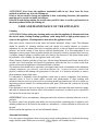
Checking gas tightness and pressure
Before checking the gas pressure, it is necessary to check the tightness of the gas installation up to
the nozzle with a leak-finder spray to ensure that no damage has been done to the appliance during
transportation. Then, it is possible to check the inlet pressure, which can be carried out by means of
a pressure gauge, either a “U” gauge or an electronic gauge with a minimum definition of 0,1 mbar.
In order to measure the gas pressure, remove the screw (1) from the pressure outlet (2) and connect
it to the pressure gauge pipe. Open the appliance gas supply valve, check the pressure output, and
close the valve. Remove the pressure gauge pipe and screw the screws correctly into the pressure
outlet. The pressure valve has to be within the minimum and maximum values shown in the table
TYPES OF GAS.
If the pressure measured is not within the limits shown in the table, find out the cause. After solving
the problem, check the pressure again.

24/199
Checking the appliance power
Normally it is sufficient to check that the nozzles installed are the right ones and that the burners
function properly. If desired, it is possible to check the power absorbed by using the “Volumetric
Method”, measuring the volume of gas output supplied to the appliance in time units with the aid of
a chronometer and a counter. The right comparison volume [E], measured in litres per hour (l/h) or
in litres per minute (l/min), can be obtained using the formula shown below dividing the nominal
and minimum outputs (power) shown in the table of burner features by the lowest heat capacity of
the gas type pre-arranged for the appliance. This value can be found in the norm tables or can be
provided by the local gas supply company.
The reading has to be done when the appliance is already in function.
Checking pilot burner
Check the flame of the pilot burner, which must be neither too short nor too high but must lap the
thermocouple and have a sharp form; otherwise, it is necessary to check the size of the nozzle
depending on the pilot version, as specified in the following paragraphs.
Checking regulation of primary air
All the main burners are provided with primary air regulation. It is necessary to carry out the check
observing the values shown in the air regulation column of the burner features tables. In order to
regulate the primary air, proceed as specified in the following paragraphs.
ATTENTION! All the parts protected and sealed by manufacturer can not be regulated by
the installer if not specifically indicated.
MAINTENANCE
ATTENTION! Before doing any kind of maintenance or repairs, make sure that the
appliance is disconnected from the electric mains and that the gas cut-off valve is closed.
The following maintenance operations have to be carried out at least once a year by specialized
personnel. It is advisable to have a maintenance contract.
Check for correct functioning of all control and safety devices;
Check for correct ignition of burners and proper functioning at minimum;
Check the tightness of the gas pipes;
Check the condition of the power cable;
Clean the evacuation pipes of type "B" appliances, following the prescriptions in force in the
country of installation;
The gas tap should be lubricated, but this operation is quite difficult and its results are not very
reliable. Therefore, it is advisable to substitute the gas tap.
Power
Heat capacity
E =

100/199
GAS FRYERS SERIES 700
Technical features
Burners Features
Dimensions
Description of appliances
Regulation using a different gas type
Substituting components
Operating anomalies
Instructions for Use
Device care and cleaning

101/199
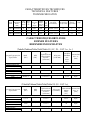
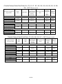
CARACTERISTIQUES TECHNIQUES
TECHNICAL FEATURES
TECHNISCHE DATEN
CARACTÉRISTIQUES BRÛLEURS
BURNER FEATURES
BRENNEREINGESCHAFTEN
(Tabella/Tableau/Table/Tafel/Tabla 31) (LV, PL - CAT. I
2H
, I
2E
)
Tipo gas/ Type gaz/ Gas
Type/ Gasart
MAX
[kW]
MIN
[kW]
Ø
Ugello/Gicleur/
Injector/Düse/
Inyector
[1/100 mm]
Ø By-pass
[1/100 mm]
Pilota/Veill
euse/Pilot/
Zündflam
me/
Piloto
[N°]
Aria/Air/Luft
/Aire “x”
[mm]
BRUCIATORE/BRÛLEUR/BURNER/BRENNER/QUEMADOR ½ module (7 l)
Natural Methane gas
5,5 x 2
-
170 x 2
-
51 x 2
Open
(G20)
BRUCIATORE/BRÛLEUR/BURNER/BRENNER/QUEMADOR 1/2 module (15 l)
Natural Methane gas
14.60
-
170 x 3
-
51
Open
(G20)
BRUCIATORE/BRÛLEUR/BURNER/BRENNER/QUEMADOR 1 module (15+15 l)
Natural Methane gas
14.60 x 2
-
170 x 3 x 2
-
51 x 2
Open
(G20)
(Tabella/Tableau/Table/Tafel/Tabla 32) (IS - CAT. I
3P
)
Tipo gas/ Type gaz/ Gas
Type/ Gasart
MAX
[kW]
MIN
[kW]
Ø
Ugello/Gicleur/
Injector/Düse/
Inyector
[1/100 mm]
Ø By-pass
[1/100 mm]
Pilota/Veilleu
se/Pilot/Zündf
lamme/
Piloto
[N°]
Aria/Air/Luft
/Aire “x”
[mm]
BRUCIATORE/BRÛLEUR/BURNER/BRENNER/QUEMADOR ½ module (7 l)
Liquid Gas PLG
5,5 x 2
-
115 x 2
-
30 x 2
Open
(G31)
BRUCIATORE/BRÛLEUR/BURNER/BRENNER/QUEMADOR 1/2 module (15 l)
Liquid Gas PLG
15.00
-
115 x 3
-
30
Open
(G31)
BRUCIATORE/BRÛLEUR/BURNER/BRENNER/QUEMADOR 1 module (15+15 l)
Liquid Gas PLG
15.00 x 2
-
115 x 3 x 2
-
30 x 2
Open
(G31)
Modele
Model
Modell
/
Dimensions/
Masse/
[mm]
Gas
Gaz (B)
[KW]
Type –
Typ -
(A)
GPL/
LPG (G30)
(D)
[Kg/h]
Methane
Erdgas
(G20) (C)
[m3/h]
Air/
Luft/
[m3/h]
Racc. gaz/
Gas fitting/
Gasanschluss/
litres cuve/
tank capacity lt/
Liter pro Tank/
kg cuve/
tank kg/
Kg pro Tank/
Kg/h
2859251
400x700x850
11
A1
0,867
1,164
22
UNI-ISO 7/1 R ½
7+7
1
18
2859171
400x700x850
15
A1/B21
1.182
1,544
30
UNI-ISO 7/1 R ½
15
2
20
2859271
800x700x850
30
A1/B21
2.365
3,089
60
UNI-ISO 7/1 R ½
15+15
2+2
40

102/199
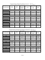
(Tabella/Tableau/Table/Tafel/Tabla 33) (CY, MT, HU, NL - CAT. I
3B/P 29mbar
)
Tipo gas/ Type gaz/ Gas
Type/ Gasart
MAX
[kW]
MIN
[kW]
Ø
Ugello/Gicleur/
Injector/Düse/
Inyector
[1/100 mm]
Ø By-pass
[1/100 mm]
Pilota/Veilleu
se/Pilot/Zündf
lamme/
Piloto
[N°]
Aria/Air/Luft
/Aire “x”
[mm]
BRUCIATORE/BRÛLEUR/BURNER/BRENNER/QUEMADOR ½ module (7 l)
Liquid Gas PLG
5,5 x 2
-
115 x 2
-
30 x 2
Open
(G30-G31)
BRUCIATORE/BRÛLEUR/BURNER/BRENNER/QUEMADOR 1/2 module (15 l)
Liquid Gas PLG
15.00
-
115 x 3
-
30
Open
(G30-G31)
BRUCIATORE/BRÛLEUR/BURNER/BRENNER/QUEMADOR 1 module (15+15 l)
Liquid Gas PLG
15.00 x 2
-
115 x 3 x 2
-
30 x 2
Open
(G31)
(Tabella/Tableau/Table/Tafel/Tabla 34) (HU- CAT. I
3B/P 50mbar
)
Tipo gas/ Type gaz/ Gas
Type/ Gasart
MAX
[kW]
MIN
[kW]
Ø
Ugello/Gicleur/
Injector/Düse/
Inyector
[1/100 mm]
Ø By-pass
[1/100 mm]
Pilota/Veilleu
se/Pilot/Zündf
lamme/
Piloto
[N°]
Aria/Air/Luft
/Aire “x”
[mm]
BRUCIATORE/BRÛLEUR/BURNER/BRENNER/QUEMADOR ½ module (7 l)
Liquid Gas PLG
5,5 x 2
-
110 x 2
-
30 x 2
Open
(G30-G31)
BRUCIATORE/BRÛLEUR/BURNER/BRENNER/QUEMADOR 1/2 module (15 l)
Liquid Gas PLG
15.00
-
100 x 3
-
30
Open
(G30-G31)
BRUCIATORE/BRÛLEUR/BURNER/BRENNER/QUEMADOR 1 module (15+15 l)
Liquid Gas PLG
15.00x 2
-
100 x 3 x 2
-
30 x 2
Open
(G31)
(Tabella/Tableau/Table/Tafel/Tabla 35) I, PT, CH, GR, GB, IE, ES – CAT. ΙΙ
2H3+
)
Tipo gas/ Type gaz/ Gas
Type/ Gasart
MAX
[kW]
MIN [kW]
Ø
Ugello/Gicleur/
Injector/Düse/
Inyector
[1/100 mm]
Ø By-pass [1/100
mm]
Pilota/Veill
euse/Pilot/
Zündflamm
e/
Piloto
[N°]
Aria/Air/L
uft/Aire
“x” [mm]
BRUCIATORE/BRÛLEUR/BURNER/BRENNER/QUEMADOR ½ module (7 l)
Natural Methan gas
5,5 x 2
-
170 x 2
-
51 x 2
Open
(G20)
Liquid gas LPG
5,5 x 2
-
115 x 2
-
30 x 2
Open
(G30-G31)
BRUCIATORE/BRÛLEUR/BURNER/BRENNER/QUEMADOR 1/2 module (15 l)
Natural Methan gas
14.60
-
170 x 3
-
51
Open
(G20)
Liquid gas LPG
15.00
-
115 x 3
-
30
Open
(G30-G31)
BRUCIATORE/BRÛLEUR/BURNER/BRENNER/QUEMADOR 1 module (15+15 l)
Natural Methan gas
14.60 x 2
-
170 x 3 x 2
-
51 x 2
Open
(G20)
Liquid gas LPG
15.00 x 2
-
115 x 3 x 2
-
30 x 2
Open
(G30-G31)

103/199
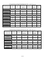
(Tabella/Tableau/Table/Tafel/Tabla 36) (CZ, FI, LT, BG, SE, DK, NO, SK, RO, EE, SI, HR,
TR - CAT. II
2H3B/P 29mbar
)
Tipo gas/ Type gaz/ Gas
Type/ Gasart
MAX
[kW]
MIN [kW]
Ø
Ugello/Gicleur/
Injector/Düse/
Inyector
[1/100 mm]
Ø By-pass [1/100
mm]
Pilota/Veill
euse/Pilot/
Zündflamm
e/
Piloto
[N°]
Aria/Air/L
uft/Aire
“x” [mm]
BRUCIATORE/BRÛLEUR/BURNER/BRENNER/QUEMADOR ½ module (7 l)
Natural Methan gas
5,5 x 2
-
170 x 2
-
51 x 2
Open
(G20)
Liquid gas LPG
5,5 x 2
-
115 x 2
-
30 x 2
Open
(G30-G31)
BRUCIATORE/BRÛLEUR/BURNER/BRENNER/QUEMADOR 1/2 module (15 l)
Natural Methan gas
14.60
-
170 x 3
-
51
Open
(G20)
Liquid gas LPG
15.00
-
115 x 3
-
30
Open
(G30-G31)
BRUCIATORE/BRÛLEUR/BURNER/BRENNER/QUEMADOR 1 module (15+15 l)
Natural Methan gas
14.60 x 2
-
170 x 3 x 2
-
51 x 2
Open
(G20)
Liquid gas LPG
15.00 x 2
-
115 x 3 x 2
-
30 x 2
Open
(G30-G31)
(Tabella/Tableau/Table/Tafel/Tabla 37) (CH, SK, DE, AT – CAT. ΙΙ
2H3B/P 50 mbar
)
Tipo gas/ Type gaz/
Gas Type/ Gasart
MAX
[kW]
MIN
[kW]
Ø
Ugello/Gicleur/
Injector/Düse/
Inyector
[1/100 mm]
Ø By-pass [1/100
mm]]
Pilota/Veilleu
se/Pilot/Zünd
flamme/
Piloto
[N°]
Aria/Air/L
uft/Aire
“x” [mm]
BRUCIATORE/BRÛLEUR/BURNER/BRENNER/QUEMADOR ½ module (7 l)
Natural Methan gas
5,5 x 2
-
170 x 2
-
51 x 2
Open
(G20)
Liquid gas LPG
5,5 x 2
-
110 x 2
-
30 x 2
Open
(G30-G31)
BRUCIATORE/BRÛLEUR/BURNER/BRENNER/QUEMADOR 1/2 module (15 l)
Natural Methan gas
14.60
-
170 x 3
-
51
Open
(G20)
Liquid gas LPG
15.00
-
100 x 3
-
30
Open
(G30-G31)
BRUCIATORE/BRÛLEUR/BURNER/BRENNER/QUEMADOR 1 module (15+15 l)
Natural Methan gas
14.60 x 2
-
170 x 3 x 2
-
51 x 2
Open
(G20)
Liquid gas LPG
15.00x 2
-
100 x 3 x 2
-
30 x 2
Open
(G30-G31)

104/199
(Tabella/Tableau/Table/Tafel/Tabla 38) (LU – CAT. ΙI
2E3P
)
Tipo gas/ Type gaz/
Gas Type/ Gasart
MAX
[kW]
MIN
[kW]
Ø
Ugello/Gicleur/
Injector/Düse/
Inyector
[1/100 mm]
Ø By-pass [1/100
mm]]
Pilota/Veilleuse
/Pilot/Zündflam
me/
Piloto
4N°]
Aria/Air/Luf
t/Aire “x”
[mm]
BRUCIATORE/BRÛLEUR/BURNER/BRENNER/QUEMADOR ½ module (7 l)
Natural Methan gas
5,5 x 2
-
170 x 2
-
51 x 2
Open
(G20)
Natural Methan gas
5,5 x 2
-
180 x 2
-
51 x 2
Open
(G25)
Liquid gas LPG
5,5 x 2
-
115 x 2
-
30 x 2
Open
(G31)
BRUCIATORE/BRÛLEUR/BURNER/BRENNER/QUEMADOR 1/2 module (15 l)
Natural Methan gas
14.60
-
170 x 3
-
51
Open
(G20)
Natural Methan gas
15,00
-
175
-
51
Open
(G25)
Liquid gas LPG
15.00
-
115 x 3
-
30
Open
(G31)
BRUCIATORE/BRÛLEUR/BURNER/BRENNER/QUEMADOR 1 module (15+15 l)
Natural Methan gas
14.60 x 2
-
170 x 3 x 2
-
51 x 2
Open
(G20)
Natural Methan gas
15,00 x 2
-
175 x 2
-
51 x 2
Open
(G25)
Liquid gas LPG
15.00 x 2
-
115 x 3 x 2
-
30 x 2
Open
(G31)
(Tabella/Tableau/Table/Tafel/Tabla 39) (FR, BE– CAT. ΙΙ
2E+3+
)
Tipo gas/ Type gaz/
Gas Type/ Gasart
MAX
[kW]
MIN
[kW]
Ø gello/Gicleur/
Injector/Düse/
Inyector
[1/100 mm]
Ø By-pass
[1/100 mm]]
Pilota/Veilleuse
/Pilot/Zündflam
me/Piloto
[N°]
Aria/Air/Luf
t/Aire “x”
[mm]
BRUCIATORE/BRÛLEUR/BURNER/BRENNER/QUEMADOR ½ module (7 l)
Natural Methan gas
5,5 x 2
-
170 x 2
-
51 x 2
Open
(G20)
Natural Methan gas
5,5 x 2
-
180 x 2
-
51 x 2
Open
(G25)
Liquid gas LPG
5,5 x 2
-
115 x 2
-
30 x 2
Open
(G30-G31)
BRUCIATORE/BRÛLEUR/BURNER/BRENNER/QUEMADOR 1/2 module (15 l)
Natural Methan gas
14.60
-
170 x 3
-
51
Open
(G20)
Natural Methan gas
15,00
-
175
-
51
Open
(G25)
Liquid gas LPG
15.00
-
115 x 3
-
30
Open
(G30-G31)
BRUCIATORE/BRÛLEUR/BURNER/BRENNER/QUEMADOR 1 module (15+15 l)
Natural Methan gas
14.60 x 2
-
170 x 3 x 2
-
51 x 2
Open
(G20)
Natural Methan gas
15,00 x 2
-
175 x 2
-
51 x 2
Open
(G25)
Liquid gas LPG
15.00 x 2
-
115 x 3 x 2
-
30 x 2
Open
(G30-G31)

105/199
(Tabella/Tableau/Table/Tafel/Tabla 40) (DE – CAT. ΙΙ
2ELL3B/P
)
Tipo gas/ Type gaz/
Gas Type/ Gasart
MAX
[kW]
MIN
[kW]
Ø ugello/Gicleur/
Injector/Düse/
Inyector
[1/100 mm]
Ø By-pass
[1/100 mm]
Pilota/Veilleu
se/Pilot/Zünd
flamme/
Piloto [N°]
Aria/Air/Lu
ft/Aire “x”
[mm]
BRUCIATORE/BRÛLEUR/BURNER/BRENNER/QUEMADOR ½ module (7 l)
Natural Methan gas
5,5 x 2
-
170 x 2
-
51 x 2
Open
(G20)
Natural Methan gas
5,5 x 2
-
160 x 2
-
51 x 2
Open
(G25)
Liquid gas LPG
5,5 x 2
-
110 x 2
-
30 x 2
Open
(G30-G31)
BRUCIATORE/BRÛLEUR/BURNER/BRENNER/QUEMADOR 1/2 module (15 l)
Natural Methan gas
14.60
-
170 x 3
-
51
Open
(G20)
Natural Methan gas
14.60
-
160 x 3
-
51
Open
(G25)
Liquid gas LPG
15.00
-
100 x 3
-
30
Open
(G30-G31)
BRUCIATORE/BRÛLEUR/BURNER/BRENNER/QUEMADOR 1 module (15+15 l)
Natural Methan gas
14.60 x 2
-
170 x 3 x 2
-
51 x 2
Open
(G20)
Natural Methan gas
14.60 x 2
-
160 x 3 x 2
-
51 x 2
Open
(G25)
Liquid gas LPG
15.00x 2
-
100 x 3 x 2
-
30 x 2
Open
(G30-G31)
(Tabella/Tableau/Table/Tafel/Tabla 41) (NL - CAT. II
2EK3B/P
)
Tipo gas/ Type gaz/
Gas Type/ Gasart
MAX
[kW]
MIN [kW]
Ø Ugello/Gicleur/
Injector/Düse/
Inyector
[1/100 mm]
Ø By-pass
[1/100 mm]
Pilota/Veilleu
se/Pilot/Zünd
flamme/
Piloto[N°]
Aria/Air/
Luft/Aire
“x” [mm]
BRUCIATORE/BRÛLEUR/BURNER/BRENNER/QUEMADOR ½ module (7 l)
Natural Methane Gas
5,5 x 2
-
175 x 2
-
51 x 2
Open
(G25.3)
Liquid Gas LPG
5,5 x 2
-
115 x 2
-
30 x 2
Open
(G30-G31)
BRUCIATORE/BRÛLEUR/BURNER/BRENNER/QUEMADOR 1/2 module (15 l)
Natural Methane Gas
15,00
-
175 x 3
-
51
Open
(G25.3)
Liquid Gas LPG
15.00
-
115 x 3
-
30
Open
(G30-G31)
BRUCIATORE/BRÛLEUR/BURNER/BRENNER/QUEMADOR 1 module (15+15 l)
Natural Methane Gas
15.00 x 2
-
175 x 3 x 2
-
51 x 2
Open
(G25.3)
Liquid Gas LPG
15.00 x 2
-
115 x 3 x 2
-
30 x 2
Open
(G30-G31)

106/199
(Tabella/Tableau/Table/Tafel/Tabla 42) (HU - CAT. II
2HS3B/P
)
Tipo gas/ Type gaz/
Gas Type/ Gasart
MAX
[kW]
MIN [kW]
Ø
Ugello/Gicleur/
Injector/Düse/
Inyector
[1/100 mm]
Ø By-pass
[1/100 mm]
Pilota/Veill
euse/Pilot/Z
ündflamme/
Piloto[N°]
Aria/Air/Luf
t/Aire “x”
[mm]
BRUCIATORE/BRÛLEUR/BURNER/BRENNER/QUEMADOR ½ module (7 l)
Natural Methane Gas
5,5 x 2
-
160
-
51
Open
(G20)
Natural Methane Gas
5,5 x 2
-
185
-
51
Open
(G25.1)
Liquid Gas LPG
5,5 x 2
-
115 x 2
-
30 x 2
Open
(G30-G31)
BRUCIATORE/BRÛLEUR/BURNER/BRENNER/QUEMADOR 1/2 module (15 l)
Natural Methane Gas
15.00
-
115 x 3
-
30
Open
(G20)
Natural Methane Gas
15,00
-
160 x 3
-
51
Open
(G25.1)
Liquid Gas LPG
15.00
-
115 x 3
-
30
Open
(G30-G31)
BRUCIATORE/BRÛLEUR/BURNER/BRENNER/QUEMADOR 1 module (15+15 l)
Natural Methane Gas
15.00 x 2
-
115 x 3 x 2
-
30 x 2
Open
(G20)
Natural Methane Gas
15,00 x 2
-
160 x 3 x 2
-
51 x 2
Open
(G25.1)
Liquid Gas LPG
15.00 x 2
-
115 x 3 x 2
-
30 x 2
Open
(G30-G31)
(Tabella/Tableau/Table/Tafel/Tabla 43) (DK - CAT. III
1a2H3B/P
)
Tipo gas/ Type gaz/
Gas Type/ Gasart
MAX
[kW]
MIN
[kW]
Ø
Ugello/Gicleur/
Injector/Düse/
Inyector
[1/100 mm]
Ø By-pass
[1/100 mm]
Pilota/Veilleu
se/Pilot/Zünd
flamme/
Piloto
[N°]
Aria/Air/Luf
t/Aire “x”
[mm]
BRUCIATORE/BRÛLEUR/BURNER/BRENNER/QUEMADOR ½ module (7 l)
Natural Methane Gas
5,5 x 2
-
170 x 2
-
51 x 2
Open
(G20)
Liquid Gas LPG
5,5 x 2
-
115 x 2
-
30 x 2
Open
(G30-G31)
BRUCIATORE/BRÛLEUR/BURNER/BRENNER/QUEMADOR 1/2 module (15 l)
Natural Methane Gas
14.60
-
170 x 3
-
51
Open
(G20)
Liquid Gas LPG
15.00
-
115 x 3
-
30
Open
(G30-G31)
BRUCIATORE/BRÛLEUR/BURNER/BRENNER/QUEMADOR 1 module (15+15 l)
Natural Methane Gas
14.60 x 2
-
170 x 3 x 2
-
51 x 2
Open
(G20)
Liquid Gas LPG
15.00 x 2
-
115 x 3 x 2
-
30 x 2
Open
(G30-G31)

107/199
(Tabella/Tableau/Table/Tafel/Tabla 44) (SE - CAT. III
1ab2H3B/P
)
Tipo gas/ Type gaz/
Gas Type/ Gasart
MAX
[kW]
MIN
[kW]
Ø
Ugello/Gicleur/
Injector/Düse/
Inyector
[1/100 mm]
Ø By-pass
[1/100 mm]
Pilota/Veilleu
se/Pilot/Zünd
flamme/
Piloto
[N°]
Aria/Air/Luf
t/Aire “x”
[mm]
BRUCIATORE/BRÛLEUR/BURNER/BRENNER/QUEMADOR ½ module (7 l)
Natural Methane Gas
5,5 x 2
-
170 x 2
-
51 x 2
Open
(G20)
Liquid Gas LPG
5,5 x 2
-
115 x 2
-
30 x 2
Open
(G30-G31)
BRUCIATORE/BRÛLEUR/BURNER/BRENNER/QUEMADOR 1/2 module (15 l)
Natural Methane Gas
14.60
-
170 x 3
-
51
Open
(G20)
Liquid Gas LPG
15.00
-
115 x 3
-
30
Open
(G30-G31)
BRUCIATORE/BRÛLEUR/BURNER/BRENNER/QUEMADOR 1 module (15+15 l)
Natural Methane Gas
14.60 x 2
-
170 x 3 x 2
-
51 x 2
Open
(G20)
Liquid Gas LPG
15.00 x 2
-
115 x 3 x 2
-
30 x 2
Open
(G30-G31)
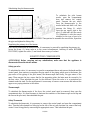
DIMENSIONS/DIMENSIONS/RAUMBEDARFMASSE
2859251
G= gas \ gaz ϕ1/2”
5,5
kW
5,5
kW

122/199
DESCRIPTION OF APPLIANCES
Gas Fryer
A sturdy structure in steel placed on four feet, which make it possible to regulate the height. The
external coating is in stainless steel.
Each vat is provided with a thermostatic safety gas valve, which enables the regulation of the
temperature in a range from 100° C to 190° inclusive; safety is ensured by means of a thermo-
couple, which is kept active by the flame of the pilot burner and by a safety thermostat against
overheating.
The pilot burner is ignited via a piezoelectric button located on the dashboard.
The vat is made entirely of stainless steel.
It is heated by means of two stainless steel heat exchangers immersed in the tank, and heated by
special steel burners suitable to operate well at the high temperatures they are subjected to.
Each tank is equipped with a basket support and a steel basket covered with a protective layer and is
equipped with a special and safe drain valve.
REGULATIONS AND SUBSTITUTIONS FOR USING A GAS DIFFERENT
FROM THE TYPE PROVIDED FOR
Functioning with a gas type different from the type provided for
In order to change to another gas type, it is necessary to substitute the nozzles of the main burners
and of the pilot burner, following the instructions in the following paragraphs. The nozzle type to be
installed can be found in tables BURNER FEATURES. The nozzles of the main burner, marked
with their diameter in hundredths, can be found in a transparent bag attached to the instruction
booklet.
If not included in the equipment, nozzles must be requested directly to the manufacturer. In the
event that the nozzles are replaced, the responsibility for the functioning of the appliance lies
entirely with the person who carried out the operation.
When the conversion is completed, check that the pipe joints are tight and that the ignition and
functioning of both the pilot and the main burner – both at minimum and maximum – are correct. It
may be advisable to check the output power.
Then, modify the technical sheet and place the sheet (provided as standard kit equipment) referring
to the new gas type in the X position.
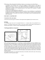
Substituting the burner nozzle
To substitute the burner nozzle, open the compartment door
and unscrew the nozzle (1) from the nozzle holder (2), and
open it completely, unscrew the nozzle (3) with a spanner
and substitute it with the nozzle suitable for the type of gas to
be used, shown in tables BURNERS FEATURES. Put back
the nozzle, tightening it well and proceed to regulate the
primary air, as indicated in the next paragraph.

123/199
Substituting the pilot burner nozzle
To substitute the pilot burner
nozzle, open the compartment
door and remove the control
panel. Unscrew the nut, which
fixes the thermocouple to the
nozzle holder and slide it off; then
unscrew the fitting (1), which
fixes the gas supply pipe to the
pilot (2) and take out the nozzle
(3). Substitute it with the nozzle
suitable for the type of gas to be
used, shown in tables BURNER FEATURES. Then proceed to assemble the new nozzle, reposition
the pipe and tighten the fitting fully.
Regulating the primary air of the burner
After having substituted the burner nozzle, it is necessary to proceed by regulating the primary air:
loosen the screw (1), bring value x to the correct measurement, referring to tables BURNER
FEATURES, tighten the screw (1) and check the accuracy of value x.
SUBSTITUTING COMPONENTS
ATTENTION! Before carrying out any substitutions, make sure that the appliance is
disconnected from the electric mains.
Safety gas valve
To substitute the valve, it is necessary to open the compartment doors and remove the knobs and the
control panel, then unscrew in sequence the pipe union of the piping which goes to the burner, the
pipe union of the piping of the pilot burner, the thermocouple and finally, the pipe union of the
ramp. Then unscrew the two screws that fix the supporting plate: the latter must be re-used to fix
the new valve. Then substitute the part. In the electronic fryers the valve is in a protection box
situated under the tank. For the replacement it is necessary to remove some screws and take out the
upper cover paying attention to the cables.
Thermocouple
To substitute the thermocouple of the fryer, the control panel must be removed, then open the
compartment door. It is then necessary to unscrew the connector of the thermocouple on the tap and
the one on the pilot unit, then substitute the part.
Safety Thermostat
To substitute the thermostat, it is necessary to remove the control panel and open the compartment
door. Then the bulb situated in a little pipe on the left of the vat, may be taken out; remove the body
control from fixing plate by unscrewing the appropriate screw. Then substitute the part.

124/199
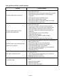
Some problems and their possible solutions
Problem
Possible solution
The pilot burner does not light on
Check that gas inlet pressure is the same as that shown in
table TYPE OF GAS
Check that the nozzle of the pilot burner is not blocked
Check that the igniter electrode, is well fixed and
connected
Check that the igniter electrode is intact.
Check that the igniter cable is intact.
Check that the piezo is intact and functions correctly
Check the gas valve or gas cock.
The pilot burner lights off after
loosening the igniter knob
Check that gas inlet pressure is the same as that shown in
table TYPE OF GAS
Check that the flame of the pilot burner laps the
thermocouple; if this is not the case, adjust the pilot
burner through the regulating screw on the valve
Check the connections between thermocouple and
thermostat
Press the gas knob in its correct position
Change the thermocouple
Check if the valve magnetic group is rusted
Check the gas valve
Check if the safety thermostat has been activated.
The pilot burner stays on but the main
burner does not light on
Check that gas inlet pressure is the same as that shown in
table TYPE OF GAS
Check that the gas nozzles are not blocked
Check that the burner holes are not blocked
Check that the gas pipe is not blocked
Check that the nozzles installed are in accordance to
tables BURNER FEATURES.
Check the gas valve
Slow and/or insufficient heat
Check that gas inlet pressure is the same as that shown in table
TYPES OF GAS
Check that the nozzles installed are in accordance to
tables BURNER FEATURES.
Check the gas valve or gas cock.
No indicator light
Check that the appliance is connected to the electric
mains
Check the power supply
Check the light bulb
Check the safety thermostat
Page is loading ...
Page is loading ...
Page is loading ...
-
 1
1
-
 2
2
-
 3
3
-
 4
4
-
 5
5
-
 6
6
-
 7
7
-
 8
8
-
 9
9
-
 10
10
-
 11
11
-
 12
12
-
 13
13
-
 14
14
-
 15
15
-
 16
16
-
 17
17
-
 18
18
-
 19
19
-
 20
20
-
 21
21
-
 22
22
-
 23
23


Bartscher 2859251 Operating instructions
- Category
- Deep fryers
- Type
- Operating instructions
Ask a question and I''ll find the answer in the document
Finding information in a document is now easier with AI
Related papers
-
Bartscher 2855081 Operating instructions
-
Bartscher 2853101 Operating instructions
-
-
Bartscher 1519811 Operating instructions
-
-
-
Bartscher 2954631 Operating instructions
-
-
-
Other documents
-
Falcon F900 G9881 User, Installation And Servicing Instructions
-
Maxima 09395017 Owner's manual
-
GGM Gastro GLGK800-E#UBK800-E Owner's manual
-
-
GGM Gastro EON20 Owner's manual
-
-
Bosch PBP6C5B89M/08 User guide
-
ROLLER GRILL RFG 12 (GP318-P) Owner's manual
-
Electrolux NCPE2RU Operating instructions
-
Whirlpool AGB 357/WP User guide