
User's Guide
HXG (Release 2) cameras (Gigabit Ethernet)
Document Version: v1.7
Release: 22.05.2017
Document Number: 11086370

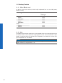
2

3
Table of Contents
1. General Information ................................................................................................. 6
2. General safety instructions ..................................................................................... 7
3. Intended Use ............................................................................................................. 7
4. General Description ................................................................................................. 7
5. Camera Models ......................................................................................................... 8
5.1 HXG – Cameras with C-Mount ............................................................................... 8
5.2 HXG-F – Cameras with F-Mount ............................................................................ 9
6. Environmental Requirements ............................................................................... 10
6.1 Temperature and Humidity Range for Storage and Operation .............................. 10
6.2 Heat Transmission ................................................................................................ 10
6.3 Mechanical Tests ....................................................................................................11
7. Process- and Data Interface .................................................................................. 12
7.1 Pin-Assignment Interface ...................................................................................... 12
7.2 Pin-Assignment Power Supply and Digital IOs ..................................................... 12
7.3 LED Signaling ....................................................................................................... 12
8. Lens install .............................................................................................................. 13
9. ProductSpecications .......................................................................................... 14
9.1 Identication of Firmware version ......................................................................... 14
9.2 Sensor Specications ........................................................................................... 14
9.2.1 Identication of Sensor Version ...................................................................... 14
9.2.2 Quantum Efciency for Baumer HXG Cameras ............................................. 14
9.2.3 Shutter ............................................................................................................ 14
9.2.4 Digitization Taps ............................................................................................ 15
9.2.5 Field of View Position ..................................................................................... 16
9.3 Timings .................................................................................................................. 17
9.3.1 Free Running Mode ........................................................................................ 17
9.3.2 Trigger Mode .................................................................................................. 18
10. Software .................................................................................................................. 22
10.1 Baumer GAPI ...................................................................................................... 22
10.2 3
rd
Party Software ................................................................................................ 22

4
11. Camera Functionalities .......................................................................................... 23
11.1 Image Acquisition ................................................................................................ 23
11.1.1 Image Format ............................................................................................... 23
11.1.2 Pixel Format .................................................................................................. 24
11.1.3 Exposure Time .............................................................................................. 26
11.1.4 PRNU / DSNU Correction (FPN - Fixed Pattern Noise) ............................... 26
11.1.5 HDR .............................................................................................................. 27
11.1.6 Look-Up-Table .............................................................................................. 27
11.1.7 Gamma Correction ....................................................................................... 28
11.1.8 Region of Interest (ROI) and Multi-ROI ........................................................ 28
11.1.9 Multi-ROI ....................................................................................................... 29
11.1.10 Binning ........................................................................................................ 30
11.1.11 Brightness Correction (Binning Correction) ................................................ 31
11.2 Color Adjustment – White Balance ...................................................................... 31
11.2.1 User-specic Color Adjustment ..................................................................... 31
11.2.2 One Push White Balance .............................................................................. 31
11.3 Analog Controls ................................................................................................... 32
11.3.1 Offset / Black Level ....................................................................................... 32
11.3.2 Gain .............................................................................................................. 32
11.4 Pixel Correction ................................................................................................... 33
11.4.1 General information ...................................................................................... 33
11.4.2 Correction Algorithm ..................................................................................... 33
11.4.3 Defectpixellist ................................................................................................ 33
11.5 Sequencer ........................................................................................................... 34
11.5.1 General Information ...................................................................................... 34
11.5.2 Baumer Optronic Sequencer in Camera xml-le .......................................... 35
11.5.3 Examples ...................................................................................................... 36
11.5.4 Capability Characteristics of Baumer GAPI Sequencer Module ................... 36
11.5.5 Double Shutter .............................................................................................. 37
11.6 Process Interface ................................................................................................ 38
11.6.1 Digital IOs ..................................................................................................... 38
11.7 Trigger Input / Trigger Delay ................................................................................ 40
11.7.1 Trigger Source .............................................................................................. 41
11.7.2 Debouncer .................................................................................................... 42
11.7.3 Flash Signal .................................................................................................. 42
11.7.4 Timer ............................................................................................................. 43
11.7.5 Counter ........................................................................................................ 44
11.8 User Sets ............................................................................................................. 44
11.9 Factory Settings .................................................................................................. 44
12. Interface Functionalities ........................................................................................ 45
12.1 Link Aggregation Group Conguration ................................................................ 45
12.1.1 Camera Control ............................................................................................ 45
12.1.2 Image data stream ....................................................................................... 45
12.2 Device Information .............................................................................................. 46
12.3 Baumer Image Info Header (Chunk) ................................................................... 47
12.4 Packet Size and Maximum Transmission Unit (MTU) ......................................... 47
12.5 "Inter Packet Gap" (IPG) .................................................................................... 48
12.5.1 Example 1: Multi Camera Operation – Minimal IPG ..................................... 48
12.5.2 Example 2: Multi Camera Operation – Optimal IPG ..................................... 49
12.6 Frame Delay ....................................................................................................... 50
12.6.1 Time Saving in Multi-Camera Operation ...................................................... 50
12.6.2 Conguration Example ................................................................................. 51

5
12.7 Multicast .............................................................................................................. 53
12.8 IP Conguration .................................................................................................. 54
12.8.1 Persistent IP ................................................................................................. 54
12.8.2 DHCP (Dynamic Host Conguration Protocol) ............................................. 54
12.8.3 LLA ............................................................................................................... 55
12.8.4 Force IP ........................................................................................................ 55
12.9 Packet Resend .................................................................................................... 56
12.9.1 Normal Case................................................................................................. 56
12.9.2 Fault 1: Lost Packet within Data Stream ...................................................... 56
12.9.3 Fault 2: Lost Packet at the End of the Data Stream ..................................... 57
12.9.4 Termination Conditions ................................................................................ 57
12.10 Message Channel ............................................................................................. 58
12.11 Action Commands ............................................................................................. 59
12.11.1 Action Command Trigger ............................................................................ 60
12.11.2 Action Command Timestamp ...................................................................... 61
13. Start-Stop-Behaviour ............................................................................................. 62
13.1 Start / Stop Acquisition (Camera) ........................................................................ 62
13.2 Start / Stop Interface ........................................................................................... 62
13.3 Pause / Resume Interface .................................................................................. 62
13.4 Acquisition Modes ............................................................................................... 62
13.4.1 Free Running ................................................................................................ 62
13.4.2 Trigger .......................................................................................................... 62
13.4.3 Sequencer .................................................................................................... 62
14. Cleaning .................................................................................................................. 63
15. Transport / Storage ................................................................................................ 63
16. Disposal .................................................................................................................. 64
17. Warranty Information ............................................................................................. 64
18. Support .................................................................................................................... 64
19. Conformity .............................................................................................................. 65
19.1 CE ....................................................................................................................... 65
19.2 FCC – Class B Device ........................................................................................ 65

6
1. General Information
Thanks for purchasing a camera of the Baumer family. This User´s Guide describes how
to connect, set up and use the camera.
Read this manual carefully and observe the notes and safety instructions!
Target group for this User´s Guide
This User's Guide is aimed at experienced users, which want to integrate camera(s) into
a vision system.
Copyright
Any duplication or reprinting of this documentation, in whole or in part, and the reproduc-
tion of the illustrations even in modied form is permitted only with the written approval of
Baumer. This document is subject to change without notice.
Classicationofthesafetyinstructions
In the User´s Guide, the safety instructions are classied as follows:
Notice
Gives helpful notes on operation or other general recommendations.
Caution
Pictogram
Indicates a possibly dangerous situation. If the situation is not avoided,slight
or minor injury could result or the device may be damaged.

7
2. General safety instructions
Observe the the following safety instruction when using the camera to avoid any damage
or injuries.
Caution
Provide adequate dissipation of heat, to ensure that the temperature does
not exceed +50°C (+122°F).
The surface of the camera may be hot during operation and immediately
after use. Be careful when handling the camera and avoid contact over a
longer period.
Notice
Use the camera only for its intended purpose! For any use that is not described in the
technical documentation poses dangers and will void the warranty. The risk has to be
borne solely by the unit´s owner.
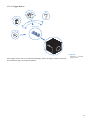
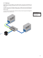
3. Intended Use
The camera is used to capture images that can be transferred over two GigE interfaces
to a PC.
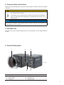
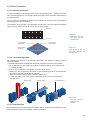
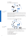
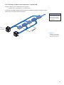
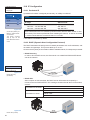
4. General Description
1
2
3
4
56
No. Description No. Description
1 (respective) lens mount 4 Digital-IO supply
2 Power supply 5 Data Port 2
3
Data Port 1 6 Signaling LED

8
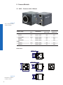
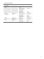
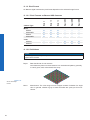
5. Camera Models
5.1 HXG – Cameras with C-Mount
Camera Type
Sensor
Size
Resolution
Full Frames
[max. fps]
Burst mode
(buffered)
Monochrome
HXG20 2/3" 2048 x 1088 105 337
HXG20NIR 2/3" 2048 x 1088 105 337
HXG40 1" 2048 x 2048 56 180
HXG40NIR 1" 2048 x 2048 56 180
Color
HXG20c 2/3" 2048 x 1088 105 337
HXG40c 1" 2048 x 2048 56 180
Dimensions
52
52
26
36
UNC 1/4 - 20
26
36
16xM3 deph 5
26
36
54,7
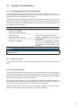
Figure1►
View of a Baumer HXG
C-Mount cameray
Figure2►
Dimensions of a Baum-
er HXG-C camera

9
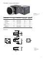
5.2 HXG-F – Cameras with F-Mount
Camera Type
Sensor
Size
Resolution
Full Frames
[max. fps]
Burst mode
(buffered)
Monochrome
HXG20-F 2/3" 2048 x 1088 105 337
HXG20NIR-F 2/3" 2048 x 1088 105 337
HXG40-F 1" 2048 x 2048 56 180
HXG40NIR-F 1" 2048 x 2048 56 180
Color
HXG20c-F 2/3" 2048 x 1088 105 337
HXG40c-F 1" 2048 x 2048 56 180
Dimensions
36
26
26
36
16 x M3 depth 6
UNC 1/4-20
52
52
26
36
55
5
12,5
10
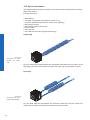
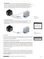
◄Figure3
View of a Baumer HXG
F-Mount camera
◄Figure4
Dimensions of a
Baumer HXG-F
camera

10
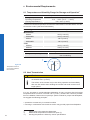
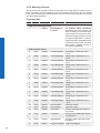
6. Environmental Requirements
6.1 Temperature and Humidity Range for Storage and Operation
*)
Temperature
Storage temperature -10°C ... +70°C ( +14°F ... +158°F)
Operating temperature* +5°C ... +50°C (+41°F ... +122°F)
Housing temperature
**)***)
max. +50°C (+122°F)
* If the environmental temperature exceeds the values listed in the table below, the cam-
era must be cooled. (see Heat Transmission)
Camera Type Environmental Temperature
Monochrome
HXG20 +49°C(+120.2°F)
HXG20NIR +49°C(+120.2°F)
HXG40 +46°C(114.8°F)
HXG40NIR +46°C(114.8°F)
Color
HXG20c +49°C(+120.2°F)
HXG40c +46°C(+114.8°F)
Humidity
Storage and Operating Humidity 10% ... 90%
Non-condensing
T
6.2 Heat Transmission
Caution
Provide adequate dissipation of heat, to ensure that the temperature does
not exceed +50°C (+122°F).
The surface of the camera may be hot during operation and immediately
after use. Be careful when handling the camera and avoid contact over a
longer period.
It is very important to provide adequate dissipation of heat, to ensure that the housing
temperature does not reach or exceed +50°C (+122°F). As there are numerous possibili-
ties for installation, Baumer do not speciy a specic method for proper heat dissipation,
but suggest the following principles:
▪ operate the cameras only in mounted condition
▪ mounting in combination with forced convection may provide proper heat dissipation
*) Please refer to the respective data sheet.
**) Measured at temperature measurement point (T).
***) Housing temperature is limited by sensor specications.
Figure5►
Temperature measure-
ment points of Baumer
HXG cameras.

11
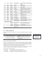
6.3 Mechanical Tests
Environmen-
tal Testing
Standard Parameter
Vibration, sinu-
sodial
IEC 60068-2-6 Search for Reso-
nance
10-2000 Hz
Amplitude under-
neath crossover
frequencies
1.5 mm
Acceleration 1 g
Test duration 15 min
Vibration,
broad band
IEC 60068-
2-64
Frequency range 20-1000 Hz
Acceleration 10 g
Displacement 5.7 mm
Test duration 300 min
Shock IEC 60068-
2-27
Puls time 11 ms / 6 ms
Acceleration 50 g / 80 g
Bump IEC60068-2-
29
Pulse Time 2 ms
Acceleration 80 g

12
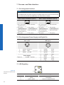
7. Process- and Data Interface
7.1 Pin-Assignment Interface
Notice
Only Port 1 supports Power over Ethernet (38 VDC .. 57 VDC).
For the data transfer, the ports are equal. For Single GigE connect one Port and for Dual
GigE connect the second Port additionally. The order does not matter.
Data / Control 1000 Base-T (Port 1) Data / Control 1000 Base-T (Port 2)
LED2
LED1
81
LED2
LED1
81
1 MX1+ (green/white)
(negative/positive V
port
)
5 MX3- (blue/white) 1 MX1+ (green/white)
(negative/positive V
port
)
5 MX3- (blue/white)
2 MX1- (green)
(negative/positive V
port
)
6 MX2- (orange)
(positive/negative V
port
)
2 MX1- (green)
(negative/positive V
port
)
6 MX2- (orange)
(positive/negative V
port
)
3 MX2+ (orange/white)
(positive/negative V
port
)
7 MX4+ (brown/white) 3 MX2+ (orange/white)
(positive/negative V
port
)
7 MX4+ (brown/white)
4 MX3+ (blue) 8 MX4- (brown) 4 MX3+ (blue) 8 MX4- (brown)
7.2 Pin-Assignment Power Supply and Digital IOs
Power Supply
M8 / 3 pins
Digital I/O
M8 / 8 pins
1
4
3
8
5
73
1
4
2
6
1 (brown) Power V
CC
1 (white) Line 5
3 (blue) GND 2 (brown) Line 1
4 (black) not used 3 (green) Line 0
4 (yellow) GND
Power Supply 5 (grey) U
ext
Power V
CC
20 VDC ... 30 VDC 6 (pink) Line 3
7 (blue) Line 4
8 (red) Line 2
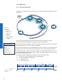
7.3 LED Signaling
1
2
3
LED Signal Meaning
1 green / green ash Link active / Receiving
2 yellow Transmitting
3 green / yellow Power on / Readout active
Figure6►
LED positions on Baumer HXG
cameras.

13
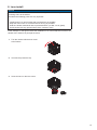
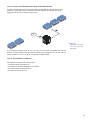
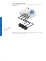
8. Lens install
Notice
Avoid contamination of the sensor and the lens by dust and airborne particles when
mounting a lens to the device!
Therefore the following points are very important:
▪ Install lenses in an environment that is as dust free as possible!
▪ Keep the dust covers on camera and lens as long as possible!
▪ Hold the camera downwards with unprotected sensor (or lter- /cover glass)!
▪ Avoid contact with any optical surface of the camera or lens!
At the example on the gures below the installation of C-mount objective is shown. At a
camera with F-Mount it is principle the same.
1.
Turn the camera with the lens mount
to the bottom.
2. Unscrew the protective cap.
3. Screw the lens on the lens mount.

14
9. ProductSpecications
9.1 IdenticationofFirmwareversion
• Label on Camera ("R2.0" is Firmware 2.0)
• BGAPI 1.x - Viewer: Camera Information: Hardware Version (CID Firmware 1.0 starts
with 02 / CID Firmware 2.0 starts with 03 (e.g. CID:020011 - Firmware 1.0)
• BGAPI 2.x Camera Explorer: Device Version: CID Firmware 1.0 starts with 02 / CID
Firmware 2.0 starts with 03 (e.g. CID:030001 - Firmware 2.0)
9.2 SensorSpecications
9.2.1 IdenticationofSensorVersion
• BGAPI 2.x - Camera Explorer - Device Control DeviceSensorType (e.g. CMV4000_
V3 - Sensor Version 3)
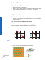
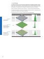
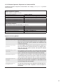
9.2.2 QuantumEfciencyforBaumerHXGCameras
The quantum efciency characteristics of monochrome (also in NIR) and color matrix sen-
sors for Baumer HXG cameras are displayed in the following graphs. The characteristic
curves for the sensors do not take the characteristics of lenses and light sources without
lters into consideration, but are measured with an AR coated cover glass.
Values relating to the respective technical data sheets of the sensors manufacturer.
350 450 550 650 750 850 950 1050
Wave Length [nm]
Quantum Efficiency [%]
HXG 20/40 (monochrome)
NIR
350 450 550 650 750 850 950 1050
Wave Length [nm]
Quantum Efficiency [%]
HXG 20/40 (color)
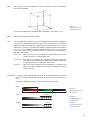
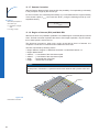
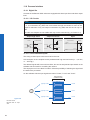
9.2.3 Shutter
All cameras of the HXG series are equipped with a global shutter.
Pixel
Active Area (Photodiode)
Storage Area
Microlens
Figure7►
Quantum efciency for
Baumer HXG cameras.
Figure8►
Structure of an imag-
ing sensor with global
shutter

15
Global shutter means that all pixels of the sensor are reset and afterwards exposed for a
specied interval (t
exposure
).
For each pixel an adjacent storage circuit exists. Once the exposure time elapsed, the
information of a pixel is transferred immediately to its circuit and read out from there.
Due to the fact that photosensitive area gets "lost" by the implementation of the circuit
area, the pixels are equipped with microlenses, which focus the light on the pixel.
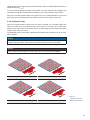
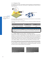
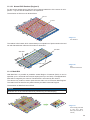
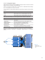
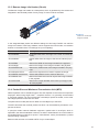
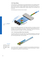
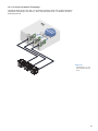
9.2.4 Digitization Taps
Due the recording speed is faster than the read out speed, the recorded images are
stored until read out in the internal memory of the camera. Thus also can be taken quick
sequences for a short time. If the memory is full, no other images can be stored. Recorded
images at full memory are lost!
The CMOSIS sensors, employed in Baumer HXG cameras can be read out up to 16 chan-
nels in parallel.
Notice
More channels increase the speed (framerate), but the use of more channels produces
a higher heat generation. Use only the maximum required number of channels!
Notice
Due to sensor characteristics in 12 bit mode only 2 or 4 channels are available.
Readout with 16 Channels Readout with 8 Channels
Readout with 4 Channels Readout with 2 Channels
◄Figure9
Digitization Tap of the
Baumer HXG cameras

16
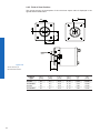
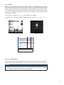
9.2.5 FieldofViewPosition
The typical accuracy by assumption of the root mean square value is displayed in the
gures and the table below:
±Z
Photosensitive
surface of the
sensor
±X
±Y
±Y
±X
±ß
M
M
R
R
Camera
Type
± x
M,typ
[mm]
± y
M,typ
[mm]
± x
R,typ
[mm]
± y
R,typ
[mm]
± β
typ
[°]
± z
typ
[mm]
HXG20 0,1 0,1 0,13 0,13 0,76 0,025
HXG20NIR 0,1 0,1 0,13 0,13 0,76 0,025
HXG40 0,1 0,1 0,13 0,13 0,65 0,025
HXG40NIR 0,1 0,1 0,13 0,13 0,65 0,025
Figure10►
Sensor accuracy of
Baumer HXG cameras.

17
9.3 Timings
Notice
Overlapped mode can be switched off with setting the readout mode to sequential shut-
ter instead of overlapped shutter.
The image acquisition consists of two separate, successively processed components.
Exposing the pixels on the photosensitive surface of the sensor is only the rst part of the
image acquisition. After completion of the rst step, the pixels are read out.
Thereby the exposure time (t
exposure
) can be adjusted by the user, however, the time need-
ed for the readout (t
readout
) is given by the particular sensor and image format.
Baumer cameras can be operated with two modes, the Free Running Mode and the
Trigger Mode.
The cameras can be operated non-overlapped
*)
or overlapped. Depending on the mode
used, and the combination of exposure and readout time:
Non-overlapped Operation Overlapped Operation
Here the time intervals are long enough
to process exposure and readout succes-
sively.
In this operation the exposure of a frame
(n+1) takes place during the readout of
frame (n).
Exposur
e
Readout
Exposur
e
Readout
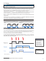
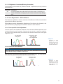
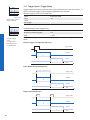
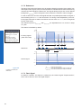
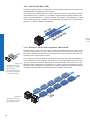
9.3.1 Free Running Mode
In the "Free Running" mode the camera records images permanently and sends them to
the PC. In order to achieve an optimal (with regard to the adjusted exposure time t
exposure
and image format) the camera is operated overlapped.
In case of exposure times equal to / less than the readout time (t
exposure
≤ t
readout
), the maxi-
mum frame rate is provided for the image format used. For longer exposure times the
frame rate of the camera is reduced.
Exposur
e
Readout
Flas
h
t
exposure(n)
t
flash(n)
t
flashdelay
t
flash(n+1)
t
readout(n+1)
t
readout(n)
t
exposure(n+1)
t
ash
= t
exposure
*) Non-overlapped means the same as sequential.
Image parameters:
Offset
Gain
Mode
Partial Scan
Timings:
A - exposure time
frame (n) effective
B - image parameters
frame (n) effective
C - exposure time
frame (n+1) effective
D - image parameters
frame (n+1) effective

18
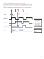
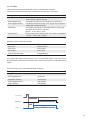
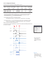
9.3.2 Trigger Mode
After a specied external event (trigger) has occurred, image acquisition is started. De-
pending on the interval of triggers used, the camera operates non-overlapped or over-
lapped in this mode.
With regard to timings in the trigger mode, the following basic formulas need to be taken
into consideration:
Case Formula
t
exposure
< t
readout
(1) t
earliestpossibletrigger(n+1)
= t
readout(n)
- t
exposure(n+1)
(2) t
notready(n+1)
= t
exposure(n)
+ t
readout(n)
- t
exposure(n+1)
t
exposure
> t
readout
(3) t
earliestpossibletrigger(n+1)
= t
exposure(n)
(4) t
notready(n+1)
= t
exposure(n)
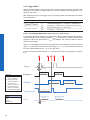
9.3.2.1 Overlapped Operation: t
exposure(n+2)
= t
exposure(n+1)
In overlapped operation attention should be paid to the time interval where the camera is
unable to process occuring trigger signals (t
notready
). This interval is situated between two
exposures. When this process time t
notready
has elapsed, the camera is able to react to
external events again.
After t
notready
has elapsed, the timing of (E) depends on the readout time of the current im-
age (t
readout(n)
) and exposure time of the next image (t
exposure(n+1)
). It can be determined by the
formulas mentioned above (no. 1 or 3, as is the case).
In case of identical exposure times, t
notready
remains the same from acquisition to acquisi-
tion.
Exposure
Readout
t
exposure(n)
t
readout(n+1)
t
readout(n)
t
exposure(n+1)
t
triggerdelay
t
min
Trigger
Flas
h
t
flash(n)
t
flashdelay
t
flash(n+1)
TriggerReady
t
notready
Image parameters:
Offset
Gain
Mode
Partial Scan
Timings:
A - exposure time
frame (n) effective
B - image parameters
frame (n) effective
C - exposure time
frame (n+1) effective
D - image parameters
frame (n+1) effective
E - earliest possible trigger

19
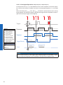
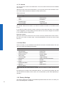
9.3.2.2 Overlapped Operation: t
exposure(n+2)
> t
exposure(n+1)
If the exposure time (t
exposure
) is increased from the current acquisition to the next acquisi-
tion, the time the camera is unable to process occuring trigger signals (t
notready
) is scaled
down.
This can be simulated with the formulas mentioned above (no. 2 or 4, as is the case).
Exposur
e
Readout
t
exposure(n)
t
readout(n+1)
t
readout(n)
t
exposure(n+1)
t
exposure(n+2)
t
triggerdelay
t
min
Tr
igger
Flas
h
t
flash(n)
t
flashdelay
t
flash(n+1)
Tr
iggerReady
t
notready
Image parameters:
Offset
Gain
Mode
Partial Scan
Timings:
A - exposure time
frame (n) effective
B - image parameters
frame (n) effective
C - exposure time
frame (n+1) effective
D - image parameters
frame (n+1) effective
E - earliest possible trigger

20
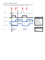
9.3.2.3 Overlapped Operation: t
exposure(n+2)
< t
exposure(n+1)
If the exposure time (t
exposure
) is decreased from the current acquisition to the next acquisi-
tion, the time the camera is unable to process occuring trigger signals (t
notready
) is scaled
up.
When decreasing the t
exposure
such, that t
notready
exceeds the pause between two incoming
trigger signals, the camera is unable to process this trigger and the acquisition of the im-
age will not start (the trigger will be skipped).
Exposure
Readout
t
exposure(n)
t
readout(n+1)
t
readout(n)
t
exposure(n+1)
t
exposure(n+2)
t
triggerdelay
t
min
Trigger
Flas
h
t
flash(n)
t
flashdelay
t
flash(n+1)
TriggerReady
t
notready
Notice
From a certain frequency of the trigger signal, skipping triggers is unavoidable. In gen-
eral, this frequency depends on the combination of exposure and readout times.
Image parameters:
Offset
Gain
Mode
Partial Scan
Timings:
A - exposure time
frame (n) effective
B - image parameters
frame (n) effective
C - exposure time
frame (n+1) effective
D - image parameters
frame (n+1) effective
E - earliest possible trigger
F - frame not started /
trigger skipped
Page is loading ...
Page is loading ...
Page is loading ...
Page is loading ...
Page is loading ...
Page is loading ...
Page is loading ...
Page is loading ...
Page is loading ...
Page is loading ...
Page is loading ...
Page is loading ...
Page is loading ...
Page is loading ...
Page is loading ...
Page is loading ...
Page is loading ...
Page is loading ...
Page is loading ...
Page is loading ...
Page is loading ...
Page is loading ...
Page is loading ...
Page is loading ...
Page is loading ...
Page is loading ...
Page is loading ...
Page is loading ...
Page is loading ...
Page is loading ...
Page is loading ...
Page is loading ...
Page is loading ...
Page is loading ...
Page is loading ...
Page is loading ...
Page is loading ...
Page is loading ...
Page is loading ...
Page is loading ...
Page is loading ...
Page is loading ...
Page is loading ...
Page is loading ...
Page is loading ...
Page is loading ...
-
 1
1
-
 2
2
-
 3
3
-
 4
4
-
 5
5
-
 6
6
-
 7
7
-
 8
8
-
 9
9
-
 10
10
-
 11
11
-
 12
12
-
 13
13
-
 14
14
-
 15
15
-
 16
16
-
 17
17
-
 18
18
-
 19
19
-
 20
20
-
 21
21
-
 22
22
-
 23
23
-
 24
24
-
 25
25
-
 26
26
-
 27
27
-
 28
28
-
 29
29
-
 30
30
-
 31
31
-
 32
32
-
 33
33
-
 34
34
-
 35
35
-
 36
36
-
 37
37
-
 38
38
-
 39
39
-
 40
40
-
 41
41
-
 42
42
-
 43
43
-
 44
44
-
 45
45
-
 46
46
-
 47
47
-
 48
48
-
 49
49
-
 50
50
-
 51
51
-
 52
52
-
 53
53
-
 54
54
-
 55
55
-
 56
56
-
 57
57
-
 58
58
-
 59
59
-
 60
60
-
 61
61
-
 62
62
-
 63
63
-
 64
64
-
 65
65
-
 66
66


Baumer HXG20 User guide
- Type
- User guide
Ask a question and I''ll find the answer in the document
Finding information in a document is now easier with AI
Related papers
-
Baumer LXG-20M.PS User guide
-
Baumer LXG-200C User guide
-
Baumer TXG20c Operating instructions
-
Baumer MXGC20c User guide
-
Baumer VLG-20M User guide
-
Baumer HXC40c Operating instructions
-
Baumer LXC-40C Operating instructions
-
Baumer VLG-22C.I User guide
-
-
Other documents
-
PYLE Audio UPDBC10 User manual
-
JAI SW-2000M-CL-65 User manual
-
Polaroid CSGS15BC23 User manual
-
 opto engineering COE-290 User manual
-
Toshiba CSGS15BC23 User manual
-
 Photon Focus MV1-D2080(IE) Series User manual
-
AMS CHR71000 User guide
-
Listen Technologies Audio Everywhere MX3 Installation guide
-
Omron FJ2 PC-Based Cameras User guide
-
 Tattile GigE TAG-2 Reference guide


