Inglis GS470LEMB0 Installation guide

Category
Ovens
Type
Installation guide

This manual is also suitable for

Table of Contents ........................................................ 2
QQ
IMPORTANT: Save installation instructions for local electrical inspector's use.
9760030
9760030
TABLEOF CONTENTS
RANGE SAFETY .......................................................................... 2
iNSTALLATiON REQUIREMENTS .............................................. 4
Tools and Parts .......................................................................... 4
Location Requirements .............................................................. 4
Electrical Requirements ............................................................ 6
Gas Supply Requirements ........................................................ 6
INSTALLATION INSTRUCTIONS ............................................ 8
Unpack Range ............................................................................ 8
install Anti-Tip Bracket .............................................................. 8
Verify Anti-Tip Bracket Location ................................................ 9
Level Range ................................................................................ 9
Make Gas Connection ................................................................ 9
Electronic ignition System ...................................................... 10
Replace Oven Racks & Storage or Warming Drawer .............. 12
Complete installation .............................................................. 12
GAS CONVERSIONS ............................................................... 13
LP Gas Conversion .................................................................. 13
Natural Gas Conversion ........................................................... 15
RANGESAFETY
Your safety and the safety of others are very important.
We have provided many important safety messages in this manual and on your appliance. Always read and obey all safety
messages.
This is the safety alert symbol
This symbol alerts you to potential hazards that can kill or hurt you and others.
Al! safety messages will follow the safety alert symbol and either the word "DANGER" or 'WARNING,"
These words mean:
You can be killed or seriously injured if you don't imrnediatemy
foltow instructions.
You can be kitied or seriously injured if you don't follow
instructions.
All safety messages will tell you what the potential hazard is, tell you how to reduce the chance of injury, and tell you what can
happen if the instructions are not followed.
WARNING: For your safety, the information in this manuam must be followed to minimize_
]
the risk of fire or explosion, or to prevent property damage, persona_ injury, or death. 1
- Do not store or use gasoline or other flammaHe vapors and _iquids in the vicinity of this
or any other appliance.
- WHAT TO DO _F YOU SMELL GAS:
®Do not try to _ight any appliance.
®Do not touch any e_ectrica_ switch; do not use any phone in your building.
®C_ear the room, buimding, or area of aH occupants.
®_mmediate_y call your gas supplier from a neighbor's phone. Follow the gas supp_ier's
instructions.
®ff you cannot reach your gas supplier, call the fire department.
- _nstaHation and service must be performed by a qualified installer, service agency, or
the gas supplier.
In the State of Massachusetts, the following installation instructions apply:
,,, Installations and repairs must be performed by a qualified or licensed contractor, plumber, or gasfitter qualified or licensed by
the State of Massachusetts.
,,, If using a ball valve, it shall be a Tohandle type.
,,, A flexible gas connector, when used, must not exceed 3 feet.
Tip Over Hazard
A child or adult can tip the range and be killed.
Connect anti-tip bracket to rear range foot.
Reconnect the antiotip bracket, if the range is moved.
Failure to fol!ow these instructions can result in death or serious burns to children and adults.
(NSTALLATIONREQUIREMENTS
Assemble the required tools and parts before starting installation.
Read and follow the safety instructions provided with any tools
listed here.
Tools needed
,. Tape measure [] Marker or pencil
[] Flat-blade screwdriver [] Masking tape
[] Phillips screwdriver [] Pipe-joint compound
[] Level resistant to LP gas
[] Hand or electric drill [] 3/16''(4.8 mm) carbide-
tipped masonry drill bit (for
[] Hammer concrete/ceramic floors)
[] Channel lock pliers [] Noncorrosive leak-detection
[] Pipe wrench solution
[] ls/16"comb(nation wrench For LP/Natural Gas
[] %" drive ratchet Conversions
[] %" nut driver [] 1/2"combination wrench
[] 1/8"(3.2 mm) drill bit (for [] 7 mm combination wrench
wood floors) [] 7 mm nut driver
[] Size T20 Torx screwdriver
Parts supplied
Check that allparts are included.
c
A.Anti-tip Bracket
B. Plasticanchors (2)
C. #10x ½"screws (2)
Brackets must be securely mounted to subfioor. Thickness of
flooring may require longer screws to anchor bracket to
subfioor. Longer screws are available from your local
hardware store.
Parts needed
Check local codes and consult gas supplier. Check existing gas
supply and electrical supply. See "Electrical Requirements" and
"Gas Supply Requirements" sections.
IMPORTANT: Observe all governing codes and ordinances. Do
not obstruct flow of combustion and ventilation air.
[] It is the instaUer's responsibility to comply with installation
clearances specified on the model/serial rating plate. The
model/serial rating plate is located on the oven frame behind
the storage drawer panel.
[] The range should be located for convenient use in the
kitchen.
[] Recessed installations must provide complete enclosure of
the sides and rear of the range.
[] To eliminate the risk of burns or fire by reaching over heated
surface units, cabinet storage space located above the
surface units should be avoided. If cabinet storage is to be
provided, the risk can be reduced by lnstaUlng a range hood
that projects horizontally a minimum of 5" (12.7 cm) beyond
the bottom of the cabinets.
[] All openings in the wall or floor where range is to be installed
must be sealed.
[] Do not seal the range to the side cabinets.
[] Cabinet opening dimensions that are shown must be used.
Given dimensions are minimum clearances.
[] The floor anti-tip bracket must be installed. To install the anti-
tip bracket shipped with the range, see "Install Anti-Tip
Bracket" sect(on.
[] Grounded electrical supply is required. See "Electrical
Requirements" section. Proper gas supply connection must
be available. See "Gas Supply Requirements" section.
[] Contact a qualified floor covering installer to check that the
floor covering can withstand at least 200°F (93°C).
[] Use an insulated pad or 1/4"(0.64 cm) plywood under range if
installing range over carpeting.
IMPORTANT: Some cabinet and building materials are not
designed to withstand the heat produced by the oven for baking
and self-cleaning. Check with your builder or cabinet supplier to
make sure that the materials used will not discolor, delaminate or
sustain other damage.
Mobile Home - Additional (nstallation Requirements
The installation of this range must conform to the Manufactured
Home Construction and Safety Standard, Title 24 CFR, Part 3280
(formerly the Federal Standard for Mobile Home Construction and
Safety, Title 24, HUD Part 280). When such standard is not
applicable, use the Standard for Manufactured Home
Installations, ANSI A225.1/N FPA 501A or with local codes.
In Canada, the instaUatlon of this range must conform with the
current standards CAN/CSA-A240-1atest edition, or with local
codes.
Mobile home installations require:
[] When this range is installed in a mobile home, it must be
secured to the floor during transit. Any method of securing the
range is adequate as long as it conforms to the standards
(lsted above.
ProductDimensions
(68_9 cm)
depth with
handle
25" (63.5 cm)
29-7/8" (75.9 cm) width
36"
(91,4cm)
cooktop
height
46-7/8"
(119.1 cm)
overall
height
Installation Clearances
Cabinet opening dimensions shown are for 25" (64 cm)
countertop depth, 24" (61 cm) base cabinet depth and
36" (91.4 cm) counte_top height=
If the cabinet depth is greater than 24" (6! cm) oven frame must
extend beyond cabinet fronts by 1/2"(13 mm) minimum=
18" (45.7cm)
upperside cabinet
For minimum
13" (33 cm) ./clearance to
upper cabinet depth /top of cooktop,
30" (76,2 cm) min, see NOTE
_ opening width
NOTE: 24" (61 cm) minimum when bottom of wood or metal
cabinet is protected by not Iess than 1/4"(0=64cm) flame retardant
millboard covered with not less than No=28 MSG sheet steel,
0.015" (0.4 mm) stainless steel, 0=024" (0=6mm) aluminum or
0=020" (0.5 mm) copper.
30" (76.2 cm) minimum clearance between the top of the cooking
platform and the bottom of an unprotected wood or metal
cabinet=
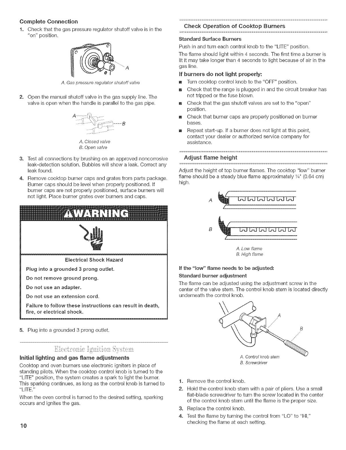
ElectricalShockHazard
Plugintoagrounded3prongoutlet.
Donotremovegroundprong.
Donotuseanadapter.
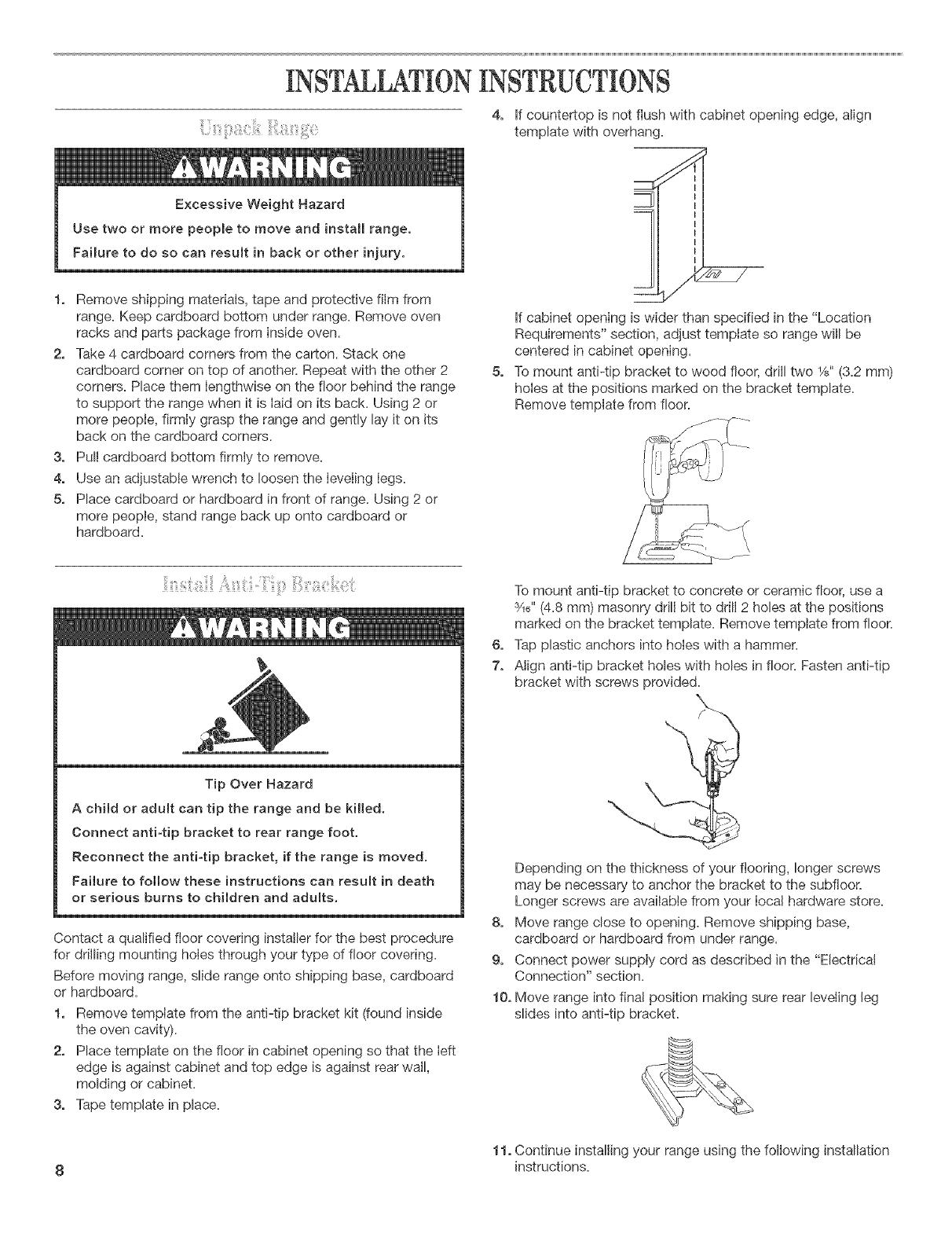
Donotuseanextension cord.
Failure to follow these instructions can result in death,
fire, or electrical shock.
IMPORTANT: The range must be electrically grounded in
accordance with Iocal codes and ordinances, or in the absence of
local codes, with the National Electrical Code, ANSI/NFPA 70 or
Canadian Electrical Code, CSA C22.1
If codes permit and a separate ground wire is used, it is
recommended that a qualified ebctrical installer determine that
the ground path is adequate.
A copy of the above code standards can be obtained from:
National Fire Protection Association
One Batterymarch Park, Quincy, MA 02269.
CSA International
8501 East Pleasant Valley Road
Cbveland, Ohio 44131-5575
[] A 120-volt, 60-Hz, AC-only, 15 amp, fused electrical circuit is
required. A time-delay fuse or circuit breaker is also
recommended. It is recommended that a separate circuit
serving only this range be provided.
[] Electronic ignition systems operate within wide voltage limits,
but proper grounding and polarity are necessary, in addition
to checking that the outlet provides 120-volt power and is
correctly grounded, the outlet must be checked by a qualified
electrician to see that it is wired with correct polarity.
This range is equipped with an electronic ignition system that
wilI not operate if plugged into an outlet that is not properly
polarized.
[] The wiring diagram is located on the underside of the storage
drawer or below the warming drawer in a clear plastic bag.
NOTE: The metal chassis of the range must be grounded in order
for the control panel to work. If the metal chassis of the range is
not grounded, no keypads will operate. Check with a qualified
electrician if you are in doubt as to whether the metal chassis of
the range is grounded.
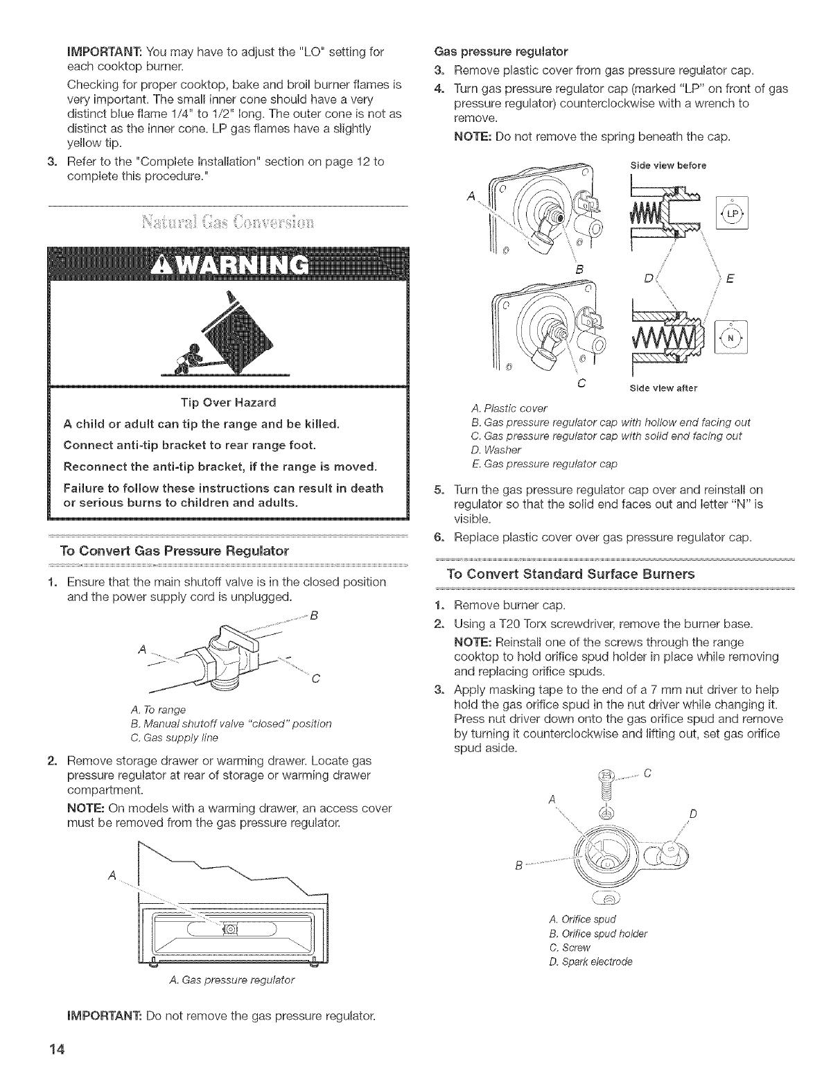
Explosion Hazard
Use a new AGA or CSA approved gas supply line.
Securely tighten aH gas connections.
If connected to LP, have a qualified person make sure
gas pressure does not exceed 14" (36 cm) water
column.
Examples of a qualified person include:
licensed heating personnel,
authorized gas company personnel, and
authorized service personnel
Faiture to do so can result in death, explosion, or fire.
Observe all governing codes and ordinances.
IMPORTANT: This installation must conform with all local codes
and ordinances, in the absence of local codes, installation must
conform with American National Standard, National Fuel Gas
Code ANSi Z223.1 - latest edition or CAN/CGA B149 - latest
edition.
Type of Gas
Natural Gas:
This range is design-certified by the American Gas Association
(A.G.A.) for use with natural gas or, after proper conversion, for
use with LP gas.
[] This range is factory set for use with natural gas. See "Gas
Conversions" section. The model/serial rating plate !ocated on
the frame behind the storage drawer has information on the
types of gas that can be used. Ifthe types of gas listed do not
include the type of gas available, check with the local gas
supplier.
LP Gas conversion:
Conversion must be done by a qualified service technician.
No attempt shall be made to convert the appliance from the gas
specified on the model/serial rating plate for use with a different
gas without consuIting the serving gas supplier. See "Gas
Conversions" section.
Gas Supply Line
Provide a gas supply line of %" rigid pipe to the range
location. A smaller size pipe on Ionger runs may result in
insufficient gas supply. Pipe joint compounds that resist the
action of LP gas must be used. Do not use TEFLOW_'ttape.
With LP gas, piping or tubing size can be _A"minimum.
Usually, LP gas suppliers determine the size and materials
used in the system.
6 €@TEFLON is a registered trademark of E,L Du Pont De Nemours and Company.
Fmexib_emetal appliance connector:
[] if local codes permit, a new A.GaA./CaSaA.design-certified,
4 - 5 ft (122 - 152.4 cm) long, !/2"(1.3 cm) ors/4'' (1.9 cm) LD.
flexible metal appliance connector may be used for
connecting range to the gas supply line.
[] A 1/2"(1.3 cm) male pipe thread is needed for connection to
the female pipe threads of the inlet to the appliance gas
pressure regulator.
[] Do not kink or damage the flexible metal tubing when moving
the range.
Rigid pipe connection:
The rigid pipe connection requires a combination of pipe fittings
to obtain an in-line connection to the range. The rigid pipe must
be level with the range connection. All strains must be removed
from the supply and fue! lines so range will be level and in line.
Burner _nput Requirements
Input ratings shown on the model/serial rating plate are for
elevations up to 2,000 ft (609.6 m).
For elevations above 2,000 ft (60%6 m), ratings are reduced at a
rate of 4% for each 1,000 ft (304.8 m) above sea level.
Gas Supply Pressure Testing
Line pressure testing above 1/2psi gauge (14" WCP)
The range and its individual manual shutoff valve must be
disconnected from the gas supply piping system during any
pressure testing of that system at test pressures greater than
1Apsi (3.5 kPa).
Line pressure testing at 1/2psi gauge (14" WCP) or _ower
The range must be isolated from the gas supply piping system by
dosing its individual manual shutoff valve during any pressure
testing of that system at test pressures equal to or less than
1Apsi (3.5 kPa).
[] Must include a shutoff valve:
The supply line must be equipped with a manua! shutoff
valve. This valve should be located in the same room but
external to the range. It should be in a location that allows
ease of opening and closing. Do not block access to shutoff
valve. The valve is for turning on or shutting off gas to the
range.
B
"_ _--=_. c/
A. Gas supp!y /ine
B. Shutoff valve "open" position
C. To range
Gas Pressure Regulator
The gas pressure regulator supplied with this range must be
used. The inlet pressure to the regulator should be as follows for
proper operation:
Natura_ Gas:
Minimum pressure: 5" WCP
Maximum pressure: 14" WCP
LP Gas:
Minimum pressure: 11" WCP
Maximum pressure: 14" WCP
Contact local gas supplier if you are not sure about the inlet
pressure.
iNSTALLATiONiNSTRUCTiONS
1. Remove shipping materials, tape and protective film from
range. Keep cardboard bottom under range. Remove oven
racks and parts package from inside oven.
2. Take 4 cardboard corners from the carton. Stack one
cardboard corner on top of another. Repeat with the other 2
corners. Place them lengthwise on the floor behind the range
to support the range when it is laid on its back. Using 2 or
more peopie, firmly grasp the range and gently lay it on its
back on the cardboard corners.
3. Pull cardboard bottom firmly to remove.
4. Use an adjustable wrench to loosen the leveling legs.
5. Place cardboard or hardboard in front of range. Using 2 or
more people, stand range back up onto cardboard or
hardboard.
If countertop is not flush with cabinet opening edge, Nigh
template with overhang.
If cabinet opening is wider than specified in the "Location
Requirements" section, adjust template so range will be
centered in cabinet opening.
To mount anti-tip bracket to wood floor, drill two 1/8"(3.2 mm)
holes at the posNons marked on the bracket template.
Remove template from floor.
Tip Over Hazard
A child or adult can tip the range and be killed.
Connect anti-tip bracket to rear range foot.
Reconnect the antiotip bracket, if the range is moved.
ISaHureto follow these instructions can result in death
or serious burns to children and adults.
Contact a qualified floor covering installer for the best procedure
for drilling mounting holes through your type of floor covering.
Before moving range, slide range onto shipping base, cardboard
or hardboard.
1. Remove template from the anti-tip bracket kit (found inside
the oven cavity).
2. Place template on the floor in cabinet opening so that the left
edge is against cabinet and top edge is against rear wall,
molding or cabinet.
3. Tape template in place.
6,
7.
To mount anti-tip bracket to concrete or ceramic floor, use a
s/18"(4.8 mm) masonry drill bit to drill 2 holes at the positions
marked on the bracket template. Remove template from floor.
Tap plastic anchors into holes with a hammer.
Align anti-tip bracket holes with holes in floor. Fasten anti-tip
bracket with screws provided.
Depending on the thickness of your flooring, longer screws
may be necessary to anchor the bracket to the subfloor.
Longer screws are available from your local hardware store.
8. Move range close to opening. Remove shipping base,
cardboard or hardboard from under range.
9. Connect power supply cord as described in the "Electrical
Connection" section.
10. Move range into final position making sure rear leveling leg
slides into anti-tip bracket.
11. Continue installing your range using the following installation
8 instructions.
1, Moverangeclosetocabinetopening.
2, Removecardboardorhardboardfromunderrange.CarefuJly
moverangeintofinalposition,
3, Pulldraweropentofirststopposition,Liftfrontofdrawerto
cleardrawerguides,Removedrawerandsetitasideona
protectedsurface.SeeUseandCareGuideforyourmodel
drawerremoval.
4,
Making sure the anti-tip bracket is installed:
[] Look for the anti-tip bracket securely attached to floor.
[] Slide range back so rear range foot is under anti-tip bracket.
5,
If installing the range in a mobile home, you must secure the
range to the floor, Any method of securing the range is
adequate as long as it conforms to the standards in the
"Location Requirements" section,
Place rack in oven. Place level on rack, first side to side; then
front to back.
If range is not level, pull range forward until rear leveling leg is
removed from the anti-tip bracket, Use %" drive ratchet and
channel lock pliers to adjust leveling legs up or down until range
is level. Push range back into position. Check that rear leveling
leg is engaged in anti-tip bracket,
NOTE: Oven must be level for satisfactory baking performance.
Typical rigid pipe connection
A combination of pipe fittings must be used to connect the range
to the existing gas line. Your connections may be different,
according to the supply line type, size and location,
1, Apply pipe-joint compound made for use with LP gas to all
pipe thread connections,
2, Using a pipe wrench to tighten, connect the gas supply to the
range.
/
A
F
!
i i'
G
A. Gas pressure regulator F{Manual gas shutoff valve
[3.90 ° elbow G. ½" or ¾" gas pipe
C. Nipple H. Nipple
D. Union L Union
E.Black iron pipe J. 90° elbow
Typical flexible connection
1, Apply pipe-joint compound made for use with LP gas to the
smaller thread ends of the flexible connector adapters (see B
and G in following illustration),
2. Attach one adapter to the gas pressure regulator and the
other adapter to the gas shutoff valve. Tighten both adapters.
3, Use a lY16"combination wrench and channel lock pliers to
attach the flexible connector to the adapters. Check that
connector is not kinked.
A B C
i
D
S
H G F
A. Gas pressure regulator
B. Use pipe-joint compound
C. Adapter (must have ½" male
pipe thread)
D. Flexible connector
E. Manual gas shutoff valve
F. ½" or ¾" gas pipe
G. Use pipe-joint compound
H,Adapter
Complete Connection
1, Check that the gas pressure regulator shutoff valve is in the
"on" position,
_ A
A.Gaspressure regulator shutoff valve
2, Open the manual shutoff valve in the gas supply line. The
valve is open when the handle is parallel to the gas pipe,
A. Closed valve
B. Open valve
3, Test all connections by brushing on an approved noncorrosive
leak-detection solution, Bubbles will show a leak, Correct any
leak found,
4, Remove cooktop burner caps and grates from parts package,
Burner caps should be level when properly positioned, If
burner caps are not properly positioned, surface burners will
not light, Place burner grates over burners and caps,
Check Operation of Cooktop Burners
Standard Surface Burners
Push in and turn each control knob to the "LFE" position,
The flame should light within 4 seconds. The first time a burner is
lit it may take longer than 4 seconds to light because of air in the
gas line,
if burners do not mightproperly:
[] Turn cooktop control knob to the "OFF" position,
[] Check that the range is plugged in and the circuit breaker has
not tripped or the fuse blown,
[] Check that the gas shutoff valves are set to the "open"
position,
[] Check that burner caps are properly positioned on burner
bases,
[] Repeat start-up, If a burner does not light at this point,
contact your dealer or authorized service company for
assistance.
Adjust flame height
Adiust the height of top burner flames. The cooktop "low" burner
flame should be a steady blue flame approximately 1/4"(0.64 cm)
high.
E_ectrica_ Shock Hazard
P_ug into a grounded 3 prong out_et.
Do not remove ground prong.
Do not use an adapter.
Do not use an extension cord.
Failure to follow these instructions can result in death,
fire, or e_ectrica_ shock.
5, Plug into a grounded 3 prong outlet,
A. Low flame
B. High flame
If the "low" flame needs to be adjusted:
Standard burner adjustment
The flame can be adjusted using the adiustment screw in the
center of the valve stem. The control knob stem is located directly
underneath the control knob.
_nitial lighting and gas flame adjustments
Cooktop and oven burners use electronic igniters in place of
standing pilots, When the cooktop control knob is turned to the
"LFE" position, the system creates a spark to light the burner,
This sparking continues, as long as the control knob is turned to
"LFE."
When the oven control is turned to the desired setting, sparking
occurs and ignites the gas,
10
A. Control knob stem
B. Screwdriver
1, Remove the control knob.
2, Hold the control knob stem with a pair of pliers, Use a small
flat-blade screwdriver to turn the screw located in the center
of the control knob stem until the flame is the proper size,
3, Replace the control knob.
4, Test the flame by turning the control from "LO" to "HI,"
checking the flame at each setting.
CheckOperationof OvenBakeBurner
Removetheovenrack,Toremovethebakeburnercover:
Removetwoscrewsattherearoftheovenbottom.Liftthe
rearoftheovenbottomupandbackuntilthefrontofthe
panelisawayfromthefrontframe.Removefromovenand
placeitonaprotectedsudace.
2. PushtheBAKEpad.
Press the START pad.
The oven bake burner should light within 8 seconds, under
certain conditions it may take the burner up to 50 to 60 seconds
to light.
Electronic igniters are used to light the bake and broil burners.
Refer to Use and Care Guide for proper operation of the oven
controls.
clean and soft in character. No yellow tips, blowing or lifting of
flame should occur.
If flame needs to be adjusted:
1. Loosen the lock screw on the air shutter located at the rear of
the broil burner.
2. Adjust the air shutter as needed.
3. Tighten lock screw.
Adjust Oven Bake Burner Flame (if needed)
1. On models with a warming drawer, remove access cover
plate (! screw) located at the back of the warming drawer
compartment.
2. Check the oven bake burner for proper flame. This flame
should have a _A"(1.3 cm) long inner cone of bluish-green,
with an outer mantle of dark blue, and should be clean and
soft in character. No yellow tips, blowing or lifting of flame
should occur.
3. Ifthe oven bake flame needs to be adjusted, locate the air
shutter near the center rear of the range. Loosen the locking
screw and rotate the air shutter until the proper flame
appears. Tighten locking screw.
4. Push CANCEL/OFF pad.
5. Reinstall flame spreader and oven bake burner cover.
Check Operation of Oven Broil Burner
1. Close the oven door.
2. Press the BROIL pad.
3. Press the START pad.
The oven burner should light within 8 seconds, under certain
conditions it may take the burner up to 50 to 60 seconds to light.
Refer to Use and Care Guide for proper operation of the oven
controls.
A. Air shutter
Adjust Oven Broil Burner Flame (if needed}
Look through oven window to check broil burner for proper
flame. This flame should have a 1/2"(1.3 cm) Iong inner cone of
bluish-green, with an outer mantle of dark blue, and shouId be
A.Lock screw
Repiace oven racks in oven cavity. Insert storage drawer or
warming drawer into slide rails on sides of drawer opening. Lift
front of drawer slightly and push firmly to close drawer.
1. Check to be sure all parts are now installed. If there is an
extra part, go back through the steps to see which step was
skipped.
2. Check to be sure you have all of your tools.
3. Dispose of/recycle all packaging materials.
4. Check to be sure the range is IeveL See "Level Range."
5. Use a miId solution of Iiquid household cleaner and warm
water to remove waxy residue caused by protective shipping
material. Dry thoroughly with a soft c!oth. For more
information, see the "Range Care" section of the Use and
Care Guide.
6. Read "Range Use" in the range Use and Care Guide.
7. Plug into a grounded 3 prong outIet.
8. Turn on surface burners and oven. See your Use and Care
Guide for specific instruction on range operation.
if range does not operate, check the following:
[] Household fuse is intact and tight; or circuit breaker has not
tripped.
[] Range is plugged into a grounded 3 prong outlet.
[] Electrical suppIy is connected.
[] See "TroubIeshooting" in your Use and Care Guide.
9. When the range has been on for 5 minutes, feel for heat. If
you do not feel heat, turn the range off and check to see that
the gas supply line shutoff valve is open.
[] If the gas supply Iine shutoff valve is closed, open it, then
repeat the 5-minute test as outlined above.
[] If the gas suppty Iine shutoff valve is open, contact a
qualified technician.
11
GASCONVERSIONS
Explosion Hazard
Use a new AGA or CSA approved gas supply line.
Securely tighten all gas connections.
if connected to LP, have a qualified person make sure
gas pressure does not exceed 14" (36 cm) water
co[umm
Examples of a qualified person include:
licensed heating personnel,
authorized gas company personnel, and
authorized service personnel
Failure to do so can result in death, explosion, or fire.
L,! Ci!ii: !il
Tip Over Hazard
A child or adult can tip the range and be kilied.
Connect anti4ip bracket to rear range foot.
Reconnect the anti4ip bracket, if the range is moved.
Failure to follow these instructions can result in death
or serious burns to children and adults.
To Convert Gas Pressure Regulator
i
1. Ensure that the manual shutoff valve is in the dosed position
and the power supply cord is unplugged.
Remove storage drawer or warming drawer. Locate gas
pressure regulator at rear of storage or warming drawer
compartment.
NOTE: On models with a warming drawer, an access cover
must be removed from the gas pressure regulator.
A
A. Gas pressure regulator
IMPORTANT: Do not remove the gas pressure regulatoK
Gas pressure regulator
3, Remove plastic cover from gas pressure regulator cap.
4, Turn gas pressure regulator cap (marked "N" on front of gas
pressure regulator) counterclockwise with a wrench to
remove.
NOTE: Do not remove the spring beneath the cap.
B
Side view before
D E
Side view after
c
A.Plastic cover
B. Gaspressur9 regulator cap with sofid end facing out
C. Gaspressure regulator cap with hoflow end facing out
D. Washer
E.Gaspressure regulator cap
5, Turn the gas pressure regulator cap over and reinstall on
regulator so that the hollow end faces out and letters "LP" are
visible.
6, Replace piastic cover over gas pressure regulator cap.
A
C
A. To range
B. Manual shutoff valve "closed" position
C. Gas supply line
12
To Convert Standard Surface Burners
1. Remove burner cap.
2. Using a T20 Torx screwdriver, remove the burner base.
NOTE: Reinstall one of the screws through the range
cooktop to hold orifice spud holder in place while removing
and replacing orifice spuds.
3. Apply masking tape to the end of a 7 mm nut driver to help
hold the gas orifice spud in the nut driver while changing it.
Press nut driver down onto the gas orifice spud and remove
by turning it counterclockwise and lifting out, set gas orifice
spud aside.
A
....... _ D
4,
A. Orifice spud
B. Orifice spud holder
C. Screw
D. Spankelectrode
Gas orifice spuds are stamped with a number, marked with
1 color dot, and have a groove in the hex area. Replace the
Natural gas orifice spud with the correct LP gas orifice spud.
_ A
A. G_OOVO
Refer to the following chart for correct LP gas orifice spud
placement.
LP Gas Orifice Spud Chart for Standard Surface Burners
Burner Rating Color Size ID Number
12,000 BTU Green/Magenta 1.03 mm L103
11,000 BTU Green/Yellow 0.99 mm L99
8,000 BTU Green/Lt. Blue 0.80 mm L80
5,000 BTU Green Brown 0.65 mm L65
NOTE: Refer to the Model Number and Serial Plate located
behind the left side of the storage or warming drawer for proper
sizing of spuds for each burner location.
5. Place Natural gas orifice spuds in plastic parts bag for future
use and keep with literature package.
6. Replace the burner base using both screws.
7. Replace burner cap.
8. Repeat steps 1-7 for the remaining burners.
To Convert Oven Bake Burner
1. Remove oven racks.
2. Use a 1/2"combination wrench to turn the orifice hood down
snug onto pin (about 2 to 21/2turns).
IMPORTANT: Do not overtighten.
The oven bake burner flame cannot be properly adjusted if
this conversion is not made. See "Adiust Oven Bake Burner
Flame" section.
A. Orifice hood
B. Pin
C. Natural gas: increase gas - increase flame size
(preset at factou for Natural gas)
D. LP gas." decrease gas - decrease flame size
To Convert Oven Broil Burner
Use a 1/2"combination wrench to turn the orifice hood down snug
onto the pin (about 2 to 21/2turns).
IMPORTANT: Do not overtighten.
The oven broil burner flame cannot be properly adiusted if this
conversion is not made. See "Adjust Oven Broil Burner Flame"
section.
A. Orifice hood
Replace oven racks in oven cavity. Insert storage drawer or
warming drawer into slide rails on sides of drawer opening. Lift
front of drawer slightly and push firmly to close drawer.
1,
2.
Refer to the "Make Gas Connection" section on page 9 for
properly connecting the range to the gas supply.
Refer to the "Electronic Ignition System" section on page 10
for proper burner ignition, operation, and burner flame
adjustments.
13
3,
IMPORTANT: You may have to adjust the "LO" setting for
each cooktop burner.
Checking for proper cooktop, bake and broil burner flames is
very important. The small inner cone should have a very
distinct blue flame 1/4" to 1/2" long. The outer cone is not as
distinct as the inner cone. LP gas flames have a slightly
yellow tip.
Refer to the "Complete Installation" section on page 12 to
complete this procedure."
;ii!_iiii¸i!i/i!i__ii_;;!!i! 'z!i!ilii;;!__!!_,zillii_i:;iil!i_:'_!!!__iii¸_!11
Tip Over Hazard
A child or adult can tip the range and be killed.
Connect antiotip bracket to rear range foot.
Reconnect the antiotip bracket, if the range is moved.
Failure to follow these instructions can result in death
or serious burns to children and adults.
To Convert Gas Pressure Regulator
1. Ensure that the main shutoff valve is in the closed position
and the power supply cord is unplugged.
2,
A. To range
B. Manual shutoff valve "closed" position
C. Gas supply line
Remove storage drawer or warming drawer. Locate gas
pressure regulator at rear of storage or warming drawer
compartment.
NOTE: On models with a warming drawer, an access cover
must be removed from the gas pressure regulator.
A
Gas pressure regulator
3. Remove plastic cover from gas pressure regulator cap.
4. Turn gas pressure regulator cap (marked "LP" on front of gas
pressure regulator) counterclockwise with a wrench to
remove.
NOTE: Do not remove the spring beneath the cap.
Side view before
/
/ E
C Side view after
A. Plastic cover
B. Gas pressure regulator cap with hollow end facing out
C. Gas pressure regulator cap with sofid end facing out
D. Washer
E. Gas pressure regulator cap
5. Turn the gas pressure regulator cap over and reinstall on
regulator so that the solid end faces out and letter "N" is
visible.
6. Replace plastic cover over gas pressure regulator cap.
To Convert Standard Surface Burners
1. Remove burner cap.
2. Using a T20 ToPAscrewdriver, remove the burner base.
NOTE: Reinstall one of the screws through the range
cooktop to hold orifice spud holder in place while removing
and replacing orifice spuds.
3. Apply masking tape to the end of a 7 mm nut driver to help
hold the gas orifice spud in the nut driver while changing it.
Press nut driver down onto the gas orifice spud and remove
by turning it counterclockwise and lifting out, set gas orifice
spud aside.
A. Gas pressure regulator
A. Orifice spud
B. Orifice spud holder
C. Screw
D. Spark electrode
IMPORTANT: Do not remove the gas pressure regulator.
14
4,
Gas orifice spuds are stamped with a number on the side.
Replace the LP gas orifice spud with the correct Natural gas
orifice spud.
A.Stamped number
Refer to the following chart for the correct Natural gas orifice
spud placement.
Natural Gas Orifice Spud Chart for Standard Surface Burners
___________________________________W_____________________________________________________________________________
Burner Rating Color Size ID Number
13,500 BTU Blue/Orange 1.86 mm N186
12,000/12,500 BTU Blue/Red 1.76 mm N176
9,500 BTU Blue/Brass 1.51 mm N151
8,000 BTU Blue/Black 1.39 mm N139
5,000 BTU Blue_g/hite 1.12 mm Nl12
NOTE: Refer to the Model Number and Serial Plate located
behind the left side of the storage or warming drawer for proper
sizing of spuds for each burner location.
5. Place LP gas orifice spuds in plastic parts bag for future use
and keep with literature package.
6. Replace the burner base using both screws.
7. Replace burner cap.
8. Repeat steps 1-7 for the remaining burners.
To Convert Oven Bake Burner
t,
2.
Remove oven racks.
Use a 1/2"combination wrench to loosen the orifice hood away
from the pin (about 2 to 21Aturns). The oven bake burner
flame cannot be properly adjusted if this conversion is not
made. See "Adiust Oven Bake Burner Flame" section.
A. Orifice hood
B. Pin
C. Natural gas: increase gas - increase flame size
(preset at factory for Natural gas)
D. LP gas: decrease gas - decrease flame size
To Convert Oven Broil Burner
Use a 1/2"combination wrench to loosen the orifice hood away
from the pin (about 2 to 21/2turns). The oven broil burner flame
cannot be properly adjusted if this conversion is not made. See
"Adjust Oven Broil Burner Flame" section.
A. OHfice hood
Repiace oven racks in oven cavity, insert storage drawer or
warming drawer into slide rails on sides of drawer opening. Lift
front of drawer slightly and push firmly to close drawer.
1. Refer to the "Make Gas Connection" section on page 9 for
properly connecting the range to the gas supply.
2. Refer to the "Electronic Ignition System" section on page 10
for proper burner ignition, operation, and burner flame
adjustments.
_MPORTANT: You may have to adiust the "LO" setting for
each cooktop burner.
Checking for proper cooktop, bake and broil burner flames is
very important. Natural gas flames do not have yellow tips.
3. Refer to the "Complete installation" section on page 12 to
complete this procedure."
15
9760030
@ 2004
AH rights reserved
6/04
Printed in U.SA
  • Page 1 1
  • Page 2 2
  • Page 3 3
  • Page 4 4
  • Page 5 5
  • Page 6 6
  • Page 7 7
  • Page 8 8
  • Page 9 9
  • Page 10 10
  • Page 11 11
  • Page 12 12
  • Page 13 13
  • Page 14 14
  • Page 15 15
  • Page 16 16

Inglis GS470LEMB0 Installation guide

Category
Ovens
Type
Installation guide
This manual is also suitable for

Ask a question and I''ll find the answer in the document

Finding information in a document is now easier with AI