Unbranded Controllers and Accessories Installation guide
- Type
- Installation guide
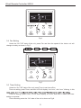
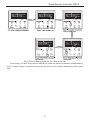
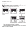
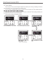
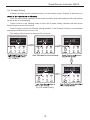
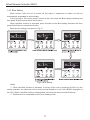
Unbranded Controllers and Accessories empower you to control your compatible devices with ease. Adjust settings, change modes, and customize your experience with a range of features. From setting timers to selecting fan speeds, these accessories offer convenience and personalized control for your devices.
Unbranded Controllers and Accessories empower you to control your compatible devices with ease. Adjust settings, change modes, and customize your experience with a range of features. From setting timers to selecting fan speeds, these accessories offer convenience and personalized control for your devices.


-
 1
1
-
 2
2
-
 3
3
-
 4
4
-
 5
5
-
 6
6
-
 7
7
-
 8
8
-
 9
9
-
 10
10
-
 11
11
-
 12
12
-
 13
13
-
 14
14
-
 15
15
-
 16
16
-
 17
17
-
 18
18
-
 19
19
-
 20
20
-
 21
21
-
 22
22
-
 23
23
-
 24
24


Unbranded Controllers and Accessories Installation guide
- Type
- Installation guide
Unbranded Controllers and Accessories empower you to control your compatible devices with ease. Adjust settings, change modes, and customize your experience with a range of features. From setting timers to selecting fan speeds, these accessories offer convenience and personalized control for your devices.
Ask a question and I''ll find the answer in the document
Finding information in a document is now easier with AI
Related papers
Other documents
-
mundoclima MUCR-H3M “MultiSplit Duct Type” Installation guide
-
GREE MC207059 User manual
-
Impecca ISAH-0922A1S User guide
-
York P-Series Single Zone System User manual
-
-
-
Friedrich FSHSR36A3A Operating instructions
-
-
-
Johnson Controls P Series 30K-36K 220V Inverter-Driven Air Conditioning Units User manual