Page is loading ...

EN
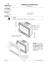
Part No. V4109-1012
V4109-1013
V4109-1014
V4109-1015
www.vinten.com

Copyright © 2015
All rights reserved.
Original Instructions: English
All rights reserved throughout the world. No part of this document may be stored in a retrieval system,
transmitted, copied or reproduced in any way, including, but not limited to, photocopy, photograph,
magnetic or other record without the prior agreement and permission in writing of the Vitec Group plc.
Disclaimer
The information contained in this manual is believed to be correct at the time of printing. Vitec Videocom
Ltd reserves the right to make changes to the information or specifications without obligation to notify any
person of such revision or changes. Changes will be incorporated in new versions of the publication.
We are making every effort to ensure that our manuals are updated on a regular basis to reflect changes
to product specifications and features. Should this manual not contain information on the core functionality
of your product, please let us know. You may be able to access the latest revision of this manual from our
website.
Vitec Videocom Ltd reserves the right to make changes to product design and functionality without
notification.
Trademarks
All product trademarks and registered trademarks are the property of The Vitec Group Plc.
All other trademarks and registered trademarks are the property of their respective companies.
Published by:
Vitec Videocom Ltd
Supports Technical Publications Department
Email: [email protected]

1
Contents
Safety. . . . . . . . . . . . . . . . . . . . . . . . . . . . . . . . . . . . . . . . . . . . . . . . . . . . . . . . . . . . . . . . . . . . . . . . . . . . 2
About this Manual . . . . . . . . . . . . . . . . . . . . . . . . . . . . . . . . . . . . . . . . . . . . . . . . . . . . . . . . . . . . . . . . . 3
Illustrations Key . . . . . . . . . . . . . . . . . . . . . . . . . . . . . . . . . . . . . . . . . . . . . . . . . . . . . . . . . . . . . . . . . 3
The APS System . . . . . . . . . . . . . . . . . . . . . . . . . . . . . . . . . . . . . . . . . . . . . . . . . . . . . . . . . . . . . . . . . . . 4
System Requirements . . . . . . . . . . . . . . . . . . . . . . . . . . . . . . . . . . . . . . . . . . . . . . . . . . . . . . . . . . . . 4
APS Scanner Unit Field of View. . . . . . . . . . . . . . . . . . . . . . . . . . . . . . . . . . . . . . . . . . . . . . . . . . . . . 4
Reflective Targets. . . . . . . . . . . . . . . . . . . . . . . . . . . . . . . . . . . . . . . . . . . . . . . . . . . . . . . . . . . . . . . . . . 6
Flat Reflective Targets . . . . . . . . . . . . . . . . . . . . . . . . . . . . . . . . . . . . . . . . . . . . . . . . . . . . . . . . . . . . 5
Cylindrical Reflective Targets . . . . . . . . . . . . . . . . . . . . . . . . . . . . . . . . . . . . . . . . . . . . . . . . . . . . . . . 6
Colouring Targets. . . . . . . . . . . . . . . . . . . . . . . . . . . . . . . . . . . . . . . . . . . . . . . . . . . . . . . . . . . . . . . . . . 8
Lighting Gel Filters . . . . . . . . . . . . . . . . . . . . . . . . . . . . . . . . . . . . . . . . . . . . . . . . . . . . . . . . . . . . . . . 8
Flat Target Colouring and Assembly . . . . . . . . . . . . . . . . . . . . . . . . . . . . . . . . . . . . . . . . . . . . . . . . . 8
Cylindrical Target Colouring and Assembly . . . . . . . . . . . . . . . . . . . . . . . . . . . . . . . . . . . . . . . . . . . . 9
Positioning Targets . . . . . . . . . . . . . . . . . . . . . . . . . . . . . . . . . . . . . . . . . . . . . . . . . . . . . . . . . . . . . . . . 8
Incorrect Target Layouts. . . . . . . . . . . . . . . . . . . . . . . . . . . . . . . . . . . . . . . . . . . . . . . . . . . . . . . . . . 12
Correct Target Layouts. . . . . . . . . . . . . . . . . . . . . . . . . . . . . . . . . . . . . . . . . . . . . . . . . . . . . . . . . . . 13
Minimum Detection Range. . . . . . . . . . . . . . . . . . . . . . . . . . . . . . . . . . . . . . . . . . . . . . . . . . . . . . . . 14
Maximum Detection Range . . . . . . . . . . . . . . . . . . . . . . . . . . . . . . . . . . . . . . . . . . . . . . . . . . . . . . . 14
Target Overlap . . . . . . . . . . . . . . . . . . . . . . . . . . . . . . . . . . . . . . . . . . . . . . . . . . . . . . . . . . . . . . . . . 15
Reflective Surfaces . . . . . . . . . . . . . . . . . . . . . . . . . . . . . . . . . . . . . . . . . . . . . . . . . . . . . . . . . . . . . 15
Example Layouts . . . . . . . . . . . . . . . . . . . . . . . . . . . . . . . . . . . . . . . . . . . . . . . . . . . . . . . . . . . . . . . 16
Maintenance . . . . . . . . . . . . . . . . . . . . . . . . . . . . . . . . . . . . . . . . . . . . . . . . . . . . . . . . . . . . . . . . . . . . . 18

2
Safety
Important information on the safe installation and operation of
this product. Read this information before operating the product.
For your personal safety, read these instructions. Do not operate
the product if you do not understand how to use it safely. Save
these instructions for future reference.
Warning Symbols Used in these Instructions
Safety cautions are included in these instructions. These safety
instructions must be followed to avoid possible personal injury and
avoid possible damage to the product.
Intended Use
The reflective target products are designed to be installed in television
studios for use with the Fusion Absolute Positioning System (APS).
When correctly installed, the targets provide mapping information for
the accurate positioning of pedestals with an APS scanner fitted on the
studio floor.
Health and Safety
Cleaning
WARNING!
Where there is a risk of personal injury or injury to others,
comments appear supported by the warning triangle symbol.
Where there is a risk of damage to the product, associated
equipment, process or surroundings, comments appear
supported by the word ‘Caution’.
WARNING! Risk of personal injury or injury to others. All
personnel must be fully trained and adhere to correct manual
handling techniques and Healthy & Safety regulations. It is
the responsibility of the local organisation to enforce safe
working practices at all times.
CAUTION! Do not use solvent or oil-based cleaners,
abrasives or wire brushes. Only use detergent-based
cleaners.

3
About this Manual
The APS reflective targets have been designed to provide critical positioning information for the correct and accurate operation of a Fusion pedestal
with an APS scanner unit installed. This manual covers the correct positioning and installation of the reflective targets in a television studio environment
to ensure the performance of the system is optimised.
Illustrations Key
Many sections in this manual use studio layout illustrations to describe the positioning of the targets.
The key objects used are:
1
Detectable flat target
2
Undetectable flat target
3
Detectable cylindrical target
4
Undetectable cylindrical target
5
Fusion pedestal with APS
6
APS scanner unit
7
Reflective object or surface
8
Wall or solid object
9
Path of laser beam (invisible I/R)
3
1
2
4
6
5
8
9
7

4
The APS System
System Requirements
The Fusion APS system operates by using reflective targets in the
studio to determine the absolute position of the Fusion pedestal(s).
When these have been installed, the Fusion pedestal equipped with an
APS scanner unit uses a spinning infrared laser read head to locate the
positions of the targets and store them as a mapping file in memory.
If the targets have been correctly positioned, the APS scanner unit can
accurately resolve the position of the pedestal anywhere on the studio
floor.
The Fusion pedestal with APS requires contact with a minimum of three
reflective targets to resolve a position.
However, it is recommended that the Fusion pedestal with APS can
maintain contact with six targets at any one time to maintain reliable
absolute positioning.
APS Scanner Unit Field of View
Although the sweep of the laser beam from the APS scanner unit is
partially blocked by the column of the pedestal, it is still capable of
detecting targets in a large field of view of 270°. This means that targets
can and should be placed to the rear of the studio.
The columns of other pedestals and tall solid objects in the studio will
also block the laser beam and this should be taken into account during
target installation.
x3
x6
270°

5
Reflective Targets
Reflective targets are available in two different types, flat or cylindrical,
depending on the requirements of the studio environment. Both types
of the target are available pre-assembled or in kit form so they can be
coloured prior to assembly to blend in to the studio set or surroundings.
Flat Reflective Targets
The flat targets are designed to be installed onto walls or other fixed
objects at a specific height above the studio floor.
Reflective properties
The entire front surface area of the flat target is reflective.
When using flat targets in an installation, it is important to take into
account the maximum angles at which the targets are capable of
reflecting the laser beam back to the APS scanner unit.
Installing Flat Reflective Targets
The flat targets must be installed at a height of 420 mm to the bottom
edge of the target, as measured from floor level.
PART NO. TARGET REFLECTOR TYPE
V4109-1012 Cylindrical target kit (for colouring)
V4109-1013 Standard pre-assembled cylindrical target
V4109-1014 Flat target kit (for colouring)
V4109-1015 Standard pre-assembled flat target
Reflective
area
120°
420 mm
(±5 mm)

6
Reflective Targets
It is recommended that either self-adhesive pads or Velcro strips are
used to attach the targets. Use generous amounts of adhesive material
to ensure the targets stay in the correct position.
Cylindrical Reflective Targets
The cylindrical targets are designed to be mounted on the floor of the
studio, particularly in instances where there are no suitable walls or
fixed objects to mount the flat targets.
Reflective properties
Unlike the flat targets, the cylindrical targets have the advantage of
being reflective at any angle.
The height of the reflective area on the cylinder has been optimised to
assume that the base of the target will be mounted on the same studio
floor level as the Fusion pedestal with APS installed.
360°
Reflective
area

7
Reflective Targets
Installing Cylindrical Reflective Targets
The cylindrical targets can be mounted to the floor permanently or
temporarily, depending on the requirements of the studio.
Permanent Mounting
Using three 6 or 8 mm floor bolts, attach the base of the cylinder to the
floor through the holes provided. The target must be mounted on a level
surface.
Temporary Mounting
To avoid the cylindrical targets becoming a permanent obstacle on the
studio floor, they can also be positioned free standing or with self
adhesive pads. However, if the targets are subsequently removed, it is
critical they are positioned back accurately for the APS scanner unit to
function correctly. Mark the studio floor with an outline of the base
footprint of the target so that they can be easily placed back into
position.

8
Colouring Targets
Colouring Targets
The targets are also supplied in kit form for self-assembly, so that they
can be coloured if this is a requirement of the studio environment.
Lighting Gel Filters
The reflective surface of the target has to be covered with a coloured
lighting gel filter with the correct lighting properties. The gel filters are
commonly available in a wide variety of colours. The gels have optical
filtering properties that allow light to pass in a specific narrow colour
range, but also in the invisible infrared spectrum. The optical properties
graph shown below is for a blue gel filter.
This filter characteristic to pass invisible infrared light means that the
laser beam from the APS scanner unit can still be reflected back
through the filter with minimal loss of signal.
Flat Target Colouring and Assembly
The flat target kit comes with the reflective material and a layer of
optically clear adhesive tape already fitted to the base plate. The
coloured gel filter is then applied on top.
1. Cut the coloured gel filter sheet slightly larger than the size of the
reflector plate.
300
400
500
600
700
800
900
20
40
60
80
100
0
Wavelength (nm)
Transmission (%)
1
2
1
Blue filter peak wavelength
2
APS scanner unit invisble infrared laser beam
1
Base plate
2
Reflective material
3
Double-sided
optically clear tape
4
Coloured gel filter
4
1
2
3
>300 mm
>75 mm

9
Colouring Targets
2. Peel off the backing on the optically clear tape and carefully apply
the coloured gel filter to the reflector plate.
3. Trim back any excess filter material from around the reflector plate
edges and remove any air bubbles trapped behind the filter.
Cylindrical Target Colouring and Assembly
The cylindrical target kit consists of the following parts:
The target bollard can be painted as required before the reflector
material is applied. This is then covered by the coloured gel filter.
1
Target bollard (unpainted)
2
Optically clear adhesive tape, 25 mm x 2
3
Self-adhesive reflector material, 300 x 241 mm
1
2
2
3
1
Bollard paint finish
2
Coloured gel filter
3
Double-sided optically
clear tape
4
Reflective material
1
2
3
4

10
Colouring Targets
1. Paint the target bollard the required colour and ensure the surface
has completely dried before proceeding.
2. Peel the backing from the self-adhesive reflector material and
carefully apply it to the bollard cylinder. The long edge of the sheet
(300 mm) must be in line with the bollard cylinder, 5 mm down
from the top of the tube.
3. Carefully wrap the reflective sheet right around the bollard
cylinder, maintaining a spacing of 5 mm from the top of the tube.
4. Cut the coloured gel filter sheet to the dimensions shown below.
OR
5 mm
300 mm
5 mm
305 mm
250 mm

11
Colouring Targets
5. Apply strips of the 25 mm optically clear tape to the long edges of
the gel filter sheet.
6. Peel the backing from one strip of the optically clear tape on the
gel filter sheet and carefully apply it to the bollard cylinder. The
taped edge of the sheet must be in line with the bollard cylinder,
2.5 mm down from the top of the tube, so that the gel filter sheet
overlaps the reflective material on both edges by the same
amount.
7. Carefully wrap the gel filter sheet tightly around the bollard tube,
maintaining an overlap of 2.5 mm over the edge of the reflective
material.
8. Peel the backing from the other strip of the optically clear tape on
the gel filter and press it down to secure the gel filter sheet in
position. Remove any air bubbles trapped in the tape joins.
305 mm
2.5 mm
2.5 mm

12
Positioning Targets
Incorrect Target Layouts
The APS scanner unit uses a map of the target positions in the studio
to resolve an absolute position for the pedestal. Targets that are
located at the same or very similar positions around the studio create a
very uniform map that can confuse the APS scanner unit and make
establishing an absolute position unreliable.
Examples of uniform and repetitive target layouts to avoid are:
Even with a variation in spacings, avoid ‘mirror image’ target positioning
layouts:

13
Positioning Targets
Correct Target Layouts
The APS scanner unit performs accurately with an asymmetric layout
of target positions. The spacing between targets should be varied by at
least 500 mm. This makes the target map more random and unique,
meaning that the Fusion pedestal with APS can always maintain an
accurate absolute position.
Examples of good asymmetric target layouts are:
If possible, introduce more random spacing between targets:
Wherever possible, maintain an even number of targets
on each side of the studio when introducing an
asymmetric target layout.

14
Positioning Targets
Minimum Detection Range
The APS scanner unit is not able to detect flat or cylindrical targets
within a radius of 0.5 metres of the laser read head. Take this into
account in a small installation area, or circumstances where the
pedestal is likely to be driven close to target positions.
Maximum Detection Range
The APS scanner unit can detect flat or cylindrical targets up to a
maximum distance of 70 metres from the read head.
>0.5 m
If a detection range longer than 70 metres is required,
reflective targets with a larger surface area can be used.
70 m

15
Positioning Targets
Target Overlap
Avoid installing targets where it is likely that they will appear too close
together from the point of view of the APS scanner unit. If the angle
between the targets as seen from the laser read head is less than 0.6°,
the system will not be able resolve them as individual positions and
both targets will be discounted.
Reflective Surfaces
Other reflective objects in the studio such as wall pipes and furniture
legs can be mistaken as targets by the APS scanner unit. This is not
normally an issue because the APS controller can be instructed that
these are not true target positions during the configuration process.
However, if a reflective object is within a proximity field of 300 mm from
a real target, the system cannot establish an accurate position. This
distance also applies to real targets being placed too close together.
Avoid installing targets near reflective objects, or cover the object with
a material with low reflective properties.
<0.6°
If required, the proximity field can be reduced during the
APS configuration process.
x = >300 mm
x
x

16
Positioning Targets
Example Layouts
The following diagrams show examples of correctly positioned targets
in studio environments, taking into account all of the guidelines
described in this manual.
Studio One
Studio Two
More than six targets in view in any position
Assymetric / random target spacing
Flat targets used in this installation
Even target numbers on each side of the studio
Flat targets installed onto studio furniture
Cyclindrical targets used in this installation
More than six targets in view in any position
Assymetric / random target spacing
Even target numbers on each side of the studio
Cylindrical targets chosen due to the absence of
suitable installation walls

17
Positioning Targets
Studio Three Studio Four
Disguise targets on studio sets by colouring
Where close target proximity to reflective objects cannot be
avoided (<300 mm), apply a non-reflective material or paint.
Pedestal 1
Pedestal 2
Both pedestals can make contact with at least six
targets in any position. This is despite the potential
for the columns of each pedestal to mask targets.
Pedestal 1 laser beam
Pedestal 2 laser beam

18
Maintenance
Routine Maintenance
If correctly secured in position, the reflective targets require no routine
maintenance other than regular cleaning.
Cleaning
To maintain the optimum performance of the targets, clean the
reflective surfaces regularly with a dry, lint-free cloth. If necessary, use
a mild detergent based cleaner.
/