Page is loading ...

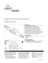
DESCRIPTION
The nVent RAYCHEM ECW-GF is an electronic ambient, pipe,
or slab sensing controller with 30-mA ground-fault protection.
It is ideal for pipe freeze protection, flow maintenance, freezer
frost heave and snow melting applications. The controller can
be programmed to maintain temperatures up to 200°F (93°C)
at voltages from 100 to 277 V and can switch current up to
30 Amperes. The ECW-GF is complete with a 25-ft (7.6-m)
temperature sensor and is housed in a NEMA 4X rated enclosure.
The controller features an AC/DC dry alarm contact relay for
monitoring critical applications such as fire protection piping.
The controller may be wall mounted or pipe mounted with the
optional FTC-PSK kit.
An optional ground-fault display panel (ECW-GF-DP) can be
added to provide ground-fault or alarm indication in applications
where the controller is mounted in inaccessible locations.
For technical support call nVent at 800-545-6258.
TOOLS REQUIRED
• Large slotted screwdriver • Needle nose pliers
• Small slotted screwdriver • Wire strippers
ADDITIONAL MATERIALS REQUIRED
(NOT PROVIDED IN THIS KIT)
• Optional remote ground-fault and heating operation display
panel (Catalog No. ECW-GF-DP)
• Appropriate mounting fasteners or optional pipe mount kit
(Catalog No. FTC-PSK)
This component is an electrical device that must
be installed correctly to ensure proper operation
and to prevent shock or fire. Read these important
warnings and carefully follow all the installation
instructions.
• To minimize the danger of fire from sustained
electrical arcing if the heating cable is damaged
or improperly installed, and to comply with the
requirements of nVent, agency certifications,
and national electrical codes, ground-fault
equipment protection must be used. Arcing may
not be stopped by conventional circuit breakers.
The ECW-GF provides the required ground-fault
equipment protection.
• The ECW-GF must be effectively grounded to
ensure proper operation. Do not rely on the
conduit system to provide a ground path. Use
the grounding terminals/screws to connect to
system ground leads.
• Component approvals and performance are based
on the use of nVent-specified parts only. Do not
use substitute parts or vinyl electrical tape.
• The black heating cable core is conductive and
can short. They must be properly insulated and
kept dry.
• Damaged bus wires can overheat or short. Do
not break bus wire strands when scoring the
jacket or core.
• Keep components and heating cable ends dry
before and during installation.
• Use only fire resistant insulation materials, such
as fiberglass wrap or flame-retardant foam.
WARNING:
A
B
C
F
E
D
APPROVALS
Nonhazardous Locations
ECW-GF
Digital Electronic Controller with Ground Fault Installation Instructions
KIT CONTENTS
Item Qty Description
A 1 Lid
B 1 Wire cover
C 1 Box with electronics
D 1 25 ft thermistor
E 1 1/2 inch compression gland
F 1 Battery connector
Pipe mounted with FTC-PSK power connection kit
ECW-GF using
RayClic power
connection kit
ECW-GF using a separate junction box

2 | nVent.com
Max. screw size: 5/32 in (4 mm)
Hole size: 0.25 in (6.4 mm) x 4
Right side entry:
3/4 NPT (1.09 in)
Bottom entry:
1 in NPT (1.29 in)
Left side entry:
1/2 in NPT (0.86 in)
1
• Attach box to wall using the
appropriate mounting fasteners.
1 in to 1/2 in reducing bushing
to RayClic-PC or FTC-P
Earth
Line/
Neutral
Line
Line/
Neutral
Line
Power
Terminal
Block
To
Heating
Cable
Power
In
Heating cables
using RayClic
power connection kit
Heating cables
using FTC-P
power connection kit
nVent.com
nVent.com
2A
Heating cable directly connected to
the ECW-GF controller
• Insert the two heating cable power
wires from the heating cable’s
junction box into the terminal block
marked “To Heating Cable” and
the ground (braid) marked “Earth”
and tighten terminals. Confirm
connection by pulling on the wires.
• For directly connected MI cable,
you must us a 1 to 1/2 inch
reducing bushing with grounding
hub.
to RayClic-P
or FTC-P
or MI heating cable
Metal Junction Box
Incoming
Power
Line
Ground
Line /
Neutral
Earth
Line/
Neutral
Line/
Neutral
Line
Line
Power
Terminal
Block
To
Heating
Cable
Power
In
2B
Connecting heating cable using a
separate junction box
Wall mounting the ECW-GF controller

nVent.com | 3
1 in
(25 mm)
Glass
cloth tape
Pipe strap
JBS-SPA
adapter for
small pipes
Note: For 1 in (25 mm)
and smaller pipes use
adapter (purchased
separately) and install
between stand and pipe.
Position
adapter
this side
up.
1
Note: Prepare the heating
cable in the stand following the
instructions included in
the nVent RAYCHEM FTC-PSK kit.
• Fasten stand to pipe with label
facing desired direction of box
opening. Do not pinch heating
cable.
• Loop and tape extra heating
cable to pipe.
O-ring
4
• Make sure o-ring is seated in groove
on transition.
• Place box onto transition and install
locknut.
• Tighten locknut.
2
Trim
3
• Screw transition onto
stand until it stops.
Tighten until slots on
transition and stand
align. Do not damage
threads on transition.
• Insert cable tie through
slots on stand and
transition and tighten
firmly to prevent
transition rotation.
• Trim off extra cable
tie.
Mounting the RAYCHEM ECW-GF controller directly on the pipe using the optional FTC-PSK pipe stand kit

4 | nVent.com
Note:
nVent
recommends
the use of a
conduit drain to
prevent water
condensation
build-up
Optional
Bottom Entry
Earth
Line/
Neutral
Line
Line/
Neutral
Line
Power
Terminal
Block
To
Heating
Cable
Power
In
1
Connecting Incoming Power
• Install conduit and fittings as shown. To
minimize loosening due to pipe vibration,
use flexible conduit.
• Pull in power and ground wires, strip off 1/2
in (13 mm) of insulation and terminate.
• Confirm by pulling on the wires.
Display
Panel
Controls
1 2 3 4 5 6 7 8
4
To heating cable junction box
Incoming
Power
Line /
Neutral
Line
Alarm
Ground
Temperature
Sensor
Remote
Display
Panel
Optional
Alarm
Contacts
Display
Panel
Contacts
Power
Terminal
Block
Temp
Sensor
Input
OPERATON
Operation: LED ON = OK
LED Blinking = Comm Error
GF TEST
GF Test: LED Blinking = Press to test
LED Blinking = OK
LED ON = Fault
GF RESET
GF Reset: LED ON
Press to Reset
ECW-GF-DP
Control/Display Panel
Ground Fault Protection
5
• Screw transition onto stand until it stops. Tighten until
slots on transition and stand align. Do not damage
threads on transition.
Thermistor
Input
T1
T2
Shield
2
Optional
Alarm
Contacts
Com
NC
NO
3
Connecting Temperature Sensor
• Adjust the length of the
temperature sensor to
meet the application
needs and strip the
sensor wires leaving 3 in
to make the connections.
Strip 1/2 in if insulation
from the wires to insert
into the terminal blocks.
• Insert the three
temperature sensor wires
into the terminal block
marked “J5.” Place the
white wire into T1, the black wire into T2 and the shield
wire into SH, and tighten terminals. Confirm connection
by pulling on the wires.
Connecting Alarm
• The controller has a
form C contact for
remote enunciation of
temperature sensor
failure and low/high
temperature alarms.
If an external alarm is
required, then alarm
wiring can exit the
enclosure via the 3/4 in
power conduit hole as
long as the insulation
rating of the alarm wire is
equal to the power wire.
Normally energized; changes state upon an alarm.
Connecting Power, Temp Sensor, Alarm and Remote Display Panel

nVent.com | 5
Menu
Down
Up
Next
2
Activating and Navigating the Menu in Set-up Mode
• To activate set-up mode, press Menu button for
approximately 3 seconds.
• The display will change to the default mode for units.
• Use the Up and Down buttons to change values.
Use the Next button to change to next display code/
parameter.
• When completed, secure the enclosure cover.
6
• Install wire cover by attaching it to plastic stand-offs.
• Program the controller. (See the section
“Programming the Controller” that follows.)
• Install lid.
• Leave these instructions with the end user for
future reference.
9 Volt
battery
(not supplied)
1A 1B
Powering Controller via Battery
(This option allows programming the controller prior to powering
the heating cable and controller circuit.)
• Connect 9 Vdc battery (not provided) to the supplied
battery connector.
• Plug the battery connector onto the two pins on the
controller marked “Battery Connector.”
Powering Controller via Line Power
• Turn on branch circuit breaker that supplies power to the
controller and heating cable.
WARNING: Shock Hazard. Secure the wire cover in place with
the four screws before energizing circuit.
Programming the ControllerTo program the controller, supply voltage to the controller in either of the following ways.

NORTH AMERICA
Tel +1.800.545.6258
Fax +1.800.527.5703
EUROPE, MIDDLE EAST, AFRICA
Tel +32.16.213.511
Fax +32.16.213.604
ASIA PACIFIC
Tel +86.21.2412.1688
Fax +86.21.5426.3167
LATIN AMERICA
Tel +1.713.868.4800
Fax +1.713.868.2333
©2018 nVent. All nVent marks and logos are owned or licensed by nVent Services GmbH or its aliates. All other trademarks are the property of their respective owners.
nVent reserves the right to change specications without notice.
Raychem-IM-H58339-ECWGF-EN-1805
The first parameter displayed during
set-up mode is units (°F or °C). Other
parameters, their default values, and
minimum and maximum values are shown
in the following table.
Menu Items Parameter Default Min. Max.
Units
(°F or °C)
°F – –
Maintain
set point
40°F (4°C)
32°F
(0°C)
200°F
(93°C)
Deadband 5°F (3°C)
2°F
(2°C)
10°F
(6°C)
High Alarm Off
Set point plus
deadband
+5°F (3°C)
230°F
(110°C)
Low Alarm Off
20°F
(–7°C)
Set point minus
deadband
Remote G-F
panel Enable
(On or Off)
Off – –
Menu Settings
In operation the display will alternate
between temperature setpoint and true
time measured temperature.
Display and Error Codes LED Status Fault
Blinking alternately red
and amber LEDs
Shorted or open
temperature sensor
Blinking alternately red
and amber LEDs
High Temperature Alarm
Blinking alternately red
and amber LEDs
Low Temperature Alarm
Blinking red LED Ground-fault trip
Blinking red LED Ground-fault circuit fail
Blinking alternately red
and amber LEDs
Remote ground-fault panel
communication failure
Display and Operation
Alarm Relay
Form C: 2 A at 277 Vac, 2 A at 48 Vdc
Normally energized; changes state upon
an alarm or loss of incoming power.
nVent.com
/