
293 WRIGHT STREET, DELAVAN, WI 53115 WWW.BERKELEYPUMPS.COM
PH: 888-782-7483
InstallatIon, operatIon & parts Manual
Models 3PL, 5PL, 7PL, 10PL,
10PLS11C, 15PLS11C
Convertible Jet Pumps
© 2013 Pentair, Ltd. All Rights Reserved. BE367 (Rev. 02/25/13)
DESCRIPTION
Corrosion resistant convertible jet pumps (Models 3PL,
5PL, 7PL, 10PL, 10PLS11C and 15PLS11C) are adaptable
to either shallow or deep well installations. A shallow well
ejector (purchase separately) is used for suction lifts of
25 feet or less and can be used with drilled (cased) wells,
driven well points, and cisterns or lakes. With a deep well
ejector installed, the convertible jet pump can be used on
wells up to 110’ deep (depending on ejector package used).
Pump is equipped with a capacitor start motor and a 30-50
psi preset pressure switch.
UNPACKING
Open carton and remove pump. Check for loose, missing, or
damaged parts.
GENERAL SAFETY INFORMATION
READ AND FOLLOW
SAFETY INSTRUCTIONS!
This is the safety alert symbol. When you see this
symbol on your pump or in this manual, look for one of the
following signal words and be alert to the potential for
personal injury!
warns about hazards that will cause serious
personal injury, death or major property damage if ignored.
warns about hazards that can cause serious
personal injury, death or major property damage if ignored.
warns about hazards that will or can cause
minor personal injury or property damage if ignored.
NOTE: Indicates special instructions which are important but
not related to hazards.
Carefully read and follow all safety instructions in this
manual and on pump.
Keep safety labels in good condition.
Replace missing or damaged safety labels.
Electrical Safety
Hazardous voltage. Can shock, burn, or
cause death. Ground pump before connecting to power
supply. Disconnect power before working on pump, motor,
or tank.
Capacitor voltage may be hazardous. To
discharge motor capacitor, hold insulated handle screwdriver
BY THE HANDLE and short capacitor terminals together. Do
not touch metal screwdriver blade or capacitor terminals. If
in doubt, consult a qualified electrician.
Wire motor for correct voltage. See “Electri cal” section
of this manual, motor nameplate, and diagram inside motor
junction box cover.
Ground motor before connecting to power supply.
Meet United States National Electri cal Code, Canadian
Elec tri cal Code, and local codes for all wiring.
Follow wiring instructions in this manual and in motor
junction box when connecting motor to power lines.
General Safety
Hazardous pressure! Do not run pump
against closed discharge. Release all pressure on system
before working on any component.
Do not touch an operating motor. Modern
motors are designed to operate at high temperatures. To
avoid burns when servicing pump, allow it to cool for 20
minutes after shut-down before handling.
Do not allow pump or any system com po nent to freeze. To
do so will void warranty.
Pump water only with this pump.
Periodically inspect pump and system components.
Wear safety glasses at all times when working on pumps.
Keep work area clean, uncluttered and properly lighted;
properly store all unused tools and equipment.
Keep visitors at a safe distance from the work areas.
Pump body may explode if used as a
booster pump unless relief valve capable of passing full
pump flow at 75 psi is installed.
California Proposition 65 Warning
This product and related accessories contain
chemicals known to the State of California to cause cancer,
birth defects or other reproductive harm.

2
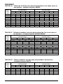
PERFORMANCE
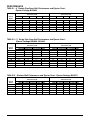
TABLE I – 4” Double Pipe Deep Well Performance and Ejector Chart -
Ejector Package BK4800
Model 3PL Model 5PL
Pressure in PSI Pressure in PSI
Feet to 20 30 40 50 60 20 30 40 50 60
Water GPM with J32P-24 Venturi and #54 Nozzle GPM with J32P-24 Venturi and #51 Nozzle
30 9.8 7.2 4.5 2.2 – 10.0 8.8 6.5 4.1 2.1
40 8.3 5.8 3.5 1.4 – 9.0 7.5 5.1 3.0 1.0
50 7.0 4.5 2.3 – – 8.3 6.4 4.0 2.0 –
60 5.5 3.3 1.3 – – 6.8 5.0 3.0 1.0 –
70 – – – – – 5.6 4.0 1.8 – –
80 – – – – – 4.0 2.5 0.75 – –
Model 3PL Model 5PL
Pressure in PSI Pressure in PSI
Feet to 20 30 40 50 60 20 30 40 50 60
Water GPM with J32P-72 Venturi and #51 Nozzle GPM with J32P-63 Venturi and #51 Nozzle
5 9.5 9.2 9.0 5.8 3.0 16.2 15.8 15.3 8.7 1.3
10 8.2 8.0 7.8 5.2 2.3 14.2 14.0 13.8 7.2 –
15 7.2 6.8 6.8 4.5 1.8 12.2 12.0 11.8 5.3 –
20 5.7 5.7 5.7 3.8 – 9.7 9.7 9.2 3.7 –
25 4.3 4.3 4.3 3.2 – 7.2 6.8 6.8 – –
TABLE II – 2” Single Pipe Deep Well Performance and Ejector Chart -
Ejector Package BK4830, BK4840
TABLE III – Shallow Well Performance and Ejector Chart - Ejector Package BK4875
Model 3PL Model 5PL
Pressure in PSI Pressure in PSI
Feet to 20 30 40 50 20 30 40 50
Water GPM with J32P-24 Venturi and #54 Nozzle GPM with J32P-24 Venturi and #54 Nozzle
30 9.7 7.0 4.5 2.8 10.0 8.6 6.2 3.8
40 8.1 5.4 3.3 2.3 8.8 7.25 4.8 2.75
50 6.7 4.0 2.6 1.7 8.5 6.0 5.5 1.6
GPM with J32P-18 Venturi and #52 Nozzle
60 3.8 2.9 2.0 1.1 4.2 3.3 2.6 1.9
70 3.2 2.3 1.5 0.7 3.6 2.8 2.1 1.3
80 – – – – 3.0 2.25 1.6 1.0
90 – – – – 2.5 1.75 1.2 0.6
100 GPM with J32P-18 Venturi and #52 Nozzle 2.0 1.3 .75 –

3
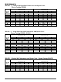
TABLE IV – 4” Double Pipe Deep Well Performance and Ejector Chart -
Ejector Package BK4800
PERFORMANCE
Model 7PL, 10PLS11C Model 10PL, 15PLS11C
Pressure in PSI Pressure in PSI
Feet to 20 30 40 50 60 20 30 40 50 60
Water GPM with J32P-24 Venturi and #51 Nozzle GPM with J32P-28 Venturi and #55 Nozzle
30 11.0 10.0 8.4 6.6 4.8 24.5 19.0 13.2 9.4 7.2
40 9.6 9.6 7.25 4.5 3.6 19.0 14.5 9.5 7.5 5.6
50 9.5 8.1 6.2 4.5 2.75 13.0 9.75 8.0 6.2 4.3
60 8.2 6.6 5.0 3.3 1.9 10.0 8.2 6.5 4.8 3.0
70 7.2 5.7 4.1 2.5 1.0 8.4 7.0 5.3 3.6 2.0
GPM with J32P-22 Venturi and #53 Nozzle
80 5.4 3.9 2.9 1.5 – 6.2 5.5 4.4 2.9 1.4
90 4.2 3.2 2.0 .75 – 5.0 4.4 3.2 1.9 –
100 – – – – – 3.5 3.2 2.2 1.1 –
110 – – – – – 2.5 2.25 1.5 – –
TABLE V – 2” Single Pipe Deep Well Performance and Ejector Chart -
Ejector Package BK4830, BK4840
Model 7PL, 10PLS11C Model 10PL, 15PLS11C
Pressure in PSI Pressure in PSI
Feet to 20 30 40 50 20 30 40 50
Water GPM with J32P-29 Venturi and #54 Nozzle GPM with J32P-29 Venturi and #54 Nozzle
30 17.8 14.4 10.6 6.4 18.6 15.6 12.3 8.7
40 9.2 11.0 7.4 4.7 15.25 12.4 9.2 6.0
50 8.5 6.0 3.7 1.6 12.3 9.0 6.4 3.2
GPM with J32P-18 Venturi and #52 Nozzle GPM with J32P-29 Venturi and #54 Nozzle
60 5.5 3.75 3.75 3.0 9.75 7.0 4.7 1.1
GPM with J32P-18 Venturi and #52 Nozzle GPM with J32P-18 Venturi and #52 Nozzle
70 5.0 4.1 3.25 2.5 5.1 4.3 3.7 3.0
80 4.3 3.5 2.7 2.0 4.6 3.9 3.25 2.6
90 3.75 3.0 2.25 1.5 4.0 3.3 2.75 2.1
100 3.25 2.5 1.75 1.1 3.6 3.0 2.4 1.75
110 2.5 1.8 1.25 0.7 2.75 2.25 1.75 1.25
TABLE VI – Shallow Well Performance and Ejector Chart - Ejector Package BK4875
Model 10PLS11C Model 15PLS11C
Pressure in PSI Pressure in PSI
Feet to 20 30 40 50 60 20 30 40 50 60
Water GPM with N32P-64 Venturi and #54 Nozzle GPM with N32P-65 Venturi and #51 Nozzle
5 21.3 21.0 20.7 13.2 4.2 26.3 26.2 26.2 21.3 8.0
10 18.8 18.7 18.3 11.1 1.7 23.7 23.3 23.2 19.2 3.5
15 16.0 15.8 15.7 8.9 – 20.3 20.2 20.0 16.3 –
20 12.8 12.7 12.3 5.7 – 16.2 16.0 15.8 11.2 –
25 8.5 8.5 8.5 – – 11.5 11.3 11.3 – –

SPECIFICATIONS
Horsepower (3PL) ........................................................... 1/3
(5PL) ........................................................... 1/2
(7PL) ........................................................... 3/4
(10PL) ............................................................ 1
(10PLS11C) ................................................... 1
(15PLS11C) ............................................. 1-1/2
Volts @ 60 Hz. ........................................................ 115/230
Phase ................................................................................. 1
Motor connected for ....................................................... 230V
Pressure Switch Setting ........................................30-50 PSI
Height ........................................................................ 11-3/4”
Width ..........................................................................10-3/4”
Length (3PL) ................................................................... 17”
(5PL) ............................................................. 17-3/4”
(7PL, 10PLS11C).......................................... 18-1/4”
(10PL, 15PLS11C) ........................................ 18-3/4”
Port Size - Inlet ............................................................ 1-1/4”
Port Size - Outlet ............................................................... 1”
Weight (3PL) ............................................................ 27 lbs.
(5PL) ............................................................ 28 lbs.
(7PL, 10PLS11C) ........................................ 30 lbs.
(10PL, 15PLS11C) ...................................... 36 lbs.
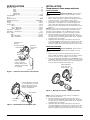
INSTALLATION
Replacing An Existing Pump
DEEP WELL
Hazardous voltage. Disconnect power to
pump before working on pump or motor.
1. Drain and remove the old pump. Check pipe for scale,
lime, rust, etc., and replace it if necessary.
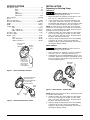
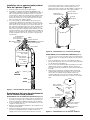
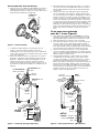
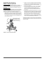
2. If your old pump has the suction pipe (the larger port
– See Figure 1) below the drive port, you will need to
install flexible pipe between the well head and the pump
so that the con nection will be correct (See Figure 2).
NOTE: Your old ejector (in the well) may not be properly
matched to your new pump. If the pump does not perform
properly, we recommend that you install a Berkeley ejector
package to match your pump and well.
3. Install the pump in the system. Make sure that all pipe
joints in the suction pipe are air-tight as well as water
tight. If the suction pipe can suck air, the pump will not
be able to pull water from the well.
4. Adjust the pump mounting height so that the plumbing
connections do not put a strain on the pump body.
Support the pipe so that the pump body does not take
the weight of piping or fittings.
SHALLOW WELL
Hazardous voltage. Disconnect power to
pump before working on pump or motor.
1. Drain and remove the old pump. Check the old pipe for
scale, lime, rust, etc., and replace it if necessary.
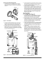
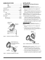
2. Install Berkeley ejector kit Model BK4875 (kits are sold
separately). Follow the instructions provided with the kit.
Be sure to align the venturi with the top hole on the front
of the pump (See Figure 3).
NOTE: Always replace the ejector when replacing the pump
in a shallow well installation.
3. Install the pump in the system. Make sure that all pipe
joints in the suction pipe are air-tight as well as water
tight. If the suction pipe can suck air, the pump will not
be able to pull water from the well.
4. Adjust the pump mounting height so that the plumbing
connections do not put a strain on the pump body.
Support the pipe so that the pump body does not take
the weight of piping or fittings.
4
Drive Pipe
sends water
down the well
to drive water
up through the
Suction Pipe
to Pump Suction
Suction
(Larger)
Port
2175 1295
Piping omitted
for clarity
Discharge
Drive
(Smaller)
Port
Figure 1 – Drive and Suction Functions
Suction
Pipe
Drive
Pipe
Well
Head
If well head and pump
don't match, twist
reinforced flexible pipe
to connect drive
and suction pipes.
2174 1295
Figure 2 – Reversed Connections to Well
Tap clamp
to seat it
2124 1195
Figure 3 – Mount Ejector – Shallow Well

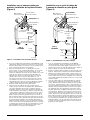
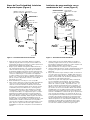
New Shallow Well, Driven Point Installation
(Figure 4)
1. Install Berkeley ejector kit BK4875 (kits are sold
separately). Follow the instructions provided with the
kit. Align the venturi with the top hole on the front of the
pump (See Figure 3).
2. Drive the well, using “drive couplings” and a “drive cap”.
“Drive fittings” are threaded all the way through and
allow the pipe ends to butt against each other so that the
driving force of the maul is carried by the pipe and not
by the threads. The ordinary fittings found in hardware
stores are not threaded all the way through the fitting
and can collapse under impact. “Drive fittings” are also
smoother than standard plumbing fittings, making ground
penetration easier.
3. Mount the pump as close to the well as possible.
4. Use the fewest possible fittings (especially elbows) when
connecting the pipe from the well point to the pump
suction port. The suction pipe should be at least as large
as the suction port on the pump (include a check valve
– See Figure 4). Support the pipe so that there are no
dips or sags in the pipe, so it doesn’t strain the pump
body, and so that it slopes slightly upward from the well
to the pump (high spots can cause air pockets which
can air lock the pump). Seal the suction pipe joints with
PTFE pipe thread sealant tape approved for use on PVC.
Joints must be air- and water-tight. If the suction pipe
can suck air, the pump cannot pull water from the well.
If one well point does not supply enough water, consider
connecting two or three well points to one suction pipe.
Cased Well Installation, 2” or Larger
Casing (Figure 5)
1. Install Berkeley ejector kit BK4875 (kits are sold
separately). Follow the instructions provided with the
kit. Align the venturi with the top hole on the front of the
pump (See Figure 3).
2. Mount the pump as close to the well as possible.
3. Assemble the foot valve, strainer, and well pipe (See
Figure 5). Make sure that the foot valve works freely.
4. Lower the pipe into the well until the strainer is five feet
above the bottom of the well. It should also be at least
10 feet below the well’s water level while the pump is
running in order to prevent the pump from sucking air.
Install a sanitary well seal.
5. Install a priming tee, priming plug, and suction pipe to the
pump (See Figure 5). Connect the pipe from the well to
the pump suction port, using the fewest possible fittings
(especially elbows) as fittings increase friction in the
pipe. The suction pipe should be at least as large as the
suction port on the pump. Use PTFE pipe thread sealant
tape on threaded pipe joints. Support the pipe so that
there are no dips or sags in the pipe, so it doesn’t strain
the pump body, and so that it slopes slightly upward from
the well to the pump (high spots can cause air pockets
which can air lock the pump). Seal the suction pipe joints
with PTFE pipe thread sealant tape. Joints must be air
and water-tight. If the suction pipe can suck air, the pump
cannot pull water from the well.
5
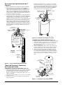
P
222 0395 NF
To Household
Water System
Suction Pipe
From Well
Pressure Gauge
and Priming Port
Drive
Coupling
Drive
Point
Check
Valve
Built-in
Check
Valve
Not
to
Scale
Relief Valve
Priming
Tee and
Plug
Figure 4 – Driven Point Installation
Figure 5 – Cased Well Installation
P
256 0395 NF
To Household
Water System
Suction Pipe
From Well
Pressure Gauge
and Priming Port
Priming
Tee and
Plug
Built-in
Check Valve
Not
to
Scale
Well
Casing
Foot
Valve
Sanitary
Well Seal
Strainer
5-10'
At least
10'
Relief Valve

INSTALLATION FOR SURFACE WATER
1. Install Berkeley ejector kit BK4875 (sold separately).
Follow the instructions provided with the kit. Align the
venturi with the top hole on the front of the pump (See
Figure 6).
2. The pump should be installed as close to the water as
possible, with the fewest possible fittings (especially
elbows) in the suction pipe. The suction pipe should be
at least as large as the suction port on the pump.
3. Assemble a foot valve and suction pipe (See Figure 7).
Make sure that the foot valve works freely. Use PTFE
pipe thread sealant tape on threaded pipe joints. Protect
the foot valve assembly from fish, trash, etc, by installing
a screen around it (See Figure 7).
4. Lower the pipe into the water until the strainer is five feet
above the bottom. It should also be at least 10 feet below
the water level while the pump is running in order to
prevent the pump from sucking air.
5. Install a priming tee, priming plug, and suction pipe to the
pump (See Figure 7). Support the pipe so that there are
no dips or sags in the pipe, so it doesn’t strain the pump
body, and so that it slopes slightly upward from the well
to the pump (high spots can cause air pockets which can
air lock the pump). Seal the suction pipe joints with PTFE
pipe thread sealant tape. Joints must be air and water-
tight. If the suction pipe can suck air, the pump cannot
pull water from the well.
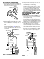
New Deep Well
4” Or Larger Well (Figure 8)
1. Assemble Berkeley ejector kit BK4800 (sold separately).
Follow the instructions included with the kit in order to
match the nozzle and venturi to your well conditions.
2. Mount the pump as close to the well as possible.
3. Connect two pipes (1” drive, 1-1⁄4” suction) to the ejector
and lower the ejector into the well until it is five feet from
the bottom. It should also be at least 10 feet below the
well’s water level while the pump is running in order to
prevent the pump from sucking air.
4. Install a sanitary well seal and connect the ejector piping
to the pump. Flexible poly pipe is recommended for ease
of installation. However, use steel nipples through the
well seal as tightening the well seal on plastic pipe can
crush the pipe.
5. Support the pipe so that there are no dips or sags in
the pipe, so it doesn’t strain the pump body, and so
that it slopes slightly upward from the well to the pump
(high spots can cause air pockets which can air lock
the pump). Seal the suction pipe joints with PTFE pipe
thread sealant tape. Joints must be air and water-tight. If
the suction pipe can suck air, the pump cannot pull water
from the well.
6
Tap clamp
to seat it
2124 1195
Figure 6 – Install Ejector
P
257 0395 NF
To Household
Water System
Suction Pipe
From Well
Foot
Valve
Screen
Pressure Gauge
and Priming Port
Built-in
Check
Valve
Not
to
Scale
At least
10'
5 to 10'
Relief Valve
Figure 7 – Surface Water Installation
To Household
Water System
Pressure
Gauge and
Priming
Plug
Well
Head
Drive (Small)
Pipe to Well
Venturi
Nozzle
Ejector
Not
to
Scale
Foot Valve
Strainer
266 0395
Relief
Valve
Suction (Large)
Pipe from Well
Figure 8 – 4” and Larger Deep Well

New Deep Well 2” Well (Figure 9)
1. Mount the pump as close to the well as possible.
2. Assemble Berkeley ejector kit BK4840 (sold separately),
well piping, and well head adapter according to the
instructions provided with the ejector package (See
Figure 9.) Use galvanized drop pipe with turned
couplings to allow proper flow. Follow the instructions
included with the kit in order to match the nozzle and
venturi to your well conditions.
3. Run two pipes (one smaller drive pipe, one larger suction
pipe) from the well to the pump. Support the pipe so that
there are no dips or sags in the pipe, so it doesn’t strain
the pump body, and so that it slopes slightly upward from
the well to the pump (high spots can cause air pockets
which can air lock the pump). Seal the suction pipe joints
with PTFE pipe thread sealant tape. Joints must be air
and water-tight. If the suction pipe can suck air, the pump
cannot pull water from the well.
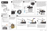
Discharge Pipe and Pressure Tank
Connections
PRE-CHARGE TANK CONNECTION (FIGURE 10)
1. Install a close nipple and a tee in the pump discharge
port (See Figure 10). The pipe size must be at least as
large as the discharge port. Run a pipe or reinforced
hose from one arm of the tee to the port on the pre-
charged tank.
2. Install a second close nipple and tee with a relief valve in
the tee.
3. Connect the other end of the second discharge tee to
your plumbing system.
4. Check the pre-charge of air in the tank with an ordinary
tire gauge. The pre-charge should be 2 psi less than the
cut-in setting of the pump’s pressure switch. The pre-
charge is measured when there is no water pressure
in the tank. Your new pump has a 30/50 psi switch, so
adjust the tank pre-charge pressure to 28 psi.
STANDARD TANK CONNECTION (FIGURE 11)
1. Install a close nipple and a tee in the pump discharge
port. Mount a relief valve in one arm of the tee.
2. Install a second close nipple and tee in the open arm of
the first tee. Put a priming plug in one arm of the second
tee.
3. Run a pipe from the open arm of the second tee to the
inlet port of your tank. The pipe size must be at least as
large as the pump discharge port.
4. Remove the 1/8” NPT pipe plug from the pump Air
Volume Control (AVC) port (See Figure 11). Run tubing
from the pump’s AVC port to the port on the AVC
mounted on the tank. See instructions provided with tank
and AVC for details.
7
Suction (Large)
Pipe from Well
To Household
Water System
Pressure Gauge
and Priming
Plug
Well
Head
Drive (Small)
Pipe to Well
Well Casing
serves as
Drive Pipe
Suction Pipe
Venturi
Nozzle
Ejector
Not
to
Scale
267 0295 NF
Relief
Valve
JET NO.
J32P-
24
Figure 9 – 2” (Single Pipe) Deep Well
P
268 0395 NF
To Household
Water System
Pressure Gauge
and Priming Plug
From
Well
Relief
Valve
Pressure
Switch
Figure 10 – Pre-charged Tank Connections
To Household
Water System
Pressure
Switch
From
Well
AVC Port
Air Volume
Control
Air Volume
Control Tube
P
Priming Tee
and Plug
276 0395 NF
Relief Valve
Figure 11 – Standard Tank Connections

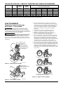
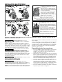
Hazardous voltage. Disconnect power before
working on pump, motor, pressure switch, or wiring.
Your Motor Terminal Board (under the motor end cover) and
Pressure Switch look like one of those shown above. Convert
to 115 Volts as shown. Do not change motor wiring if line
voltage is 230 Volts or if you have a single voltage motor.
Con nect power supply as shown for your type of switch and
your supply voltage.
Hazardous voltage. Can shock, burn, or
kill. Connect ground wire before connecting power supply
wires. Use the wire size (including the ground wire) specified
in the wiring chart (Page 10). If possible, connect the pump
to a separate branch circuit with no other appliances on it.
Explosion hazard. Do not ground to a gas
supply line.
Wiring Connections
Fire hazard. Incorrect voltage can cause a
fire or seriously damage the motor and voids the warranty.
The supply voltage must be within ±10% of the motor
nameplate voltage.
NOTE: Dual-voltage motors are factory wired for 230 volts. If
necessary, reconnect the motor for 115 volts, as shown. Do
not alter the wiring in single voltage motors.
Install, ground, wire, and maintain your pump in compliance
with the United States National Electrical Code (NEC) or the
Canadian Electrical Code (CEC), as applicable, and with all
local codes and ordinances that apply. Consult your local
building inspector for code information.
Connection Procedure
1. Connect the ground wire first as shown in Figure 12. The
ground wire must be a solid copper wire at least as large
as the power supply wires.
2. There must be a solid metal connection between the
pressure switch and the motor for motor grounding
protection. If the pressure switch is not connected to the
motor, connect the green ground screw in the switch to
the green ground screw under the motor end cover. Use
a solid copper wire at least as large as the power supply
wires.
3. Connect the ground wire to a grounded lead in a service
panel, to a metal underground water pipe, to a metal
well casing at least ten feet (3M) long, or to a ground
electrode provided by the power company or the hydro
authority.
4. Connect the power supply wires to the pressure switch
as shown in Figure 12.
8
Figure 12 – Motor wiring connections through Pressure Switch. Match motor voltage to line voltage.
Pull plug
straight
out from
terminal
board.
1.
1.
2.
2.
Plug in again
with arrow
on plug
pointing to
'115 Volts'.
A
L1
230
Volts
115
Volts
A
L1
230
Volts
115
Volts
Ground
Screw
3962 0401 A
115 V
230 V
230 Volt to 115 Volt Conversion. Move plug to change voltage.
Ground
Screw
230V
115V
230V
115V
A
A
L2
L2
L1
L1
230V
115V
A
A
L2
L2
L1
L1
230V
115V
Power Supply
Wires
230 Volt to 115 Volt Conversion. Move plug to change voltage.
Clamp the power cable to prevent strain
on the terminal screws.
Connect the green (or bare copper) ground wire
to the green ground screw.
Motor wires connect here.
Clamp the power cable to prevent strain
on the terminal screws.
Connect the green (or bare copper) ground wire
to the green ground screw.
Motor wires connect here.
3187 0398 B/WG
Power supply wires connect here.
230 Volt: Connect 2 hot wires (black and red)
here and cap the white (neutral) wire. It does
not matter which wire goes to which screw.
115 Volt: Connect one hot wire (black or red)
to one of these screws (it doesn't matter
which one). Connect the white (neutral) wire
to the other screw. Cap any remaining
black or red wires.
ELECTRICAL INSTALLATION

OPERATION
Preparing to Start the Pump – Deep Well
Never run pump dry. Running pump without
water may cause pump to overheat, damaging seal and
possibly causing burns to persons handling pump. Fill pump
with water before starting.
Never run pump against closed discharge.
To do so can boil water inside pump, causing hazardous
pressure in unit, risk of explosion and possibly scalding
persons handling pump.
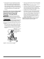
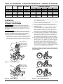
1. Open the control valve as far as possible (See Figure
13). Then remove the priming plug from the pump and fill
the pump, fill all piping between the pump and the well,
and make sure that all piping in the well is full. If you
have also installed a priming tee in the suction piping,
remove the plug from the tee and fill the suction piping.
2. Replace all fill plugs and close the control valve
completely (See Figure 14).
3. Power on! Start the pump and watch the pressure gauge.
The pressure should build rapidly to 50 psi as the pump
primes.
4. After 2 or 3 minutes, the gauge should show pressure.
If not, stop the pump, remove the fill plugs, reopen the
control valve, and refill the pump and piping. You may
have to repeat this two or three times in order to get all
the trapped air out of the piping. Don’t forget to close the
control valve each time before you start the pump.
5. When pressure has built up and stabilized at about 50
psi, slowly open the control valve (See Figure 15) and let
the pressure drop until the pressure gauge needle starts
to flutter. When the needle flutters, close the valve just
enough to stop the flutter (See Figure 15). Your pump is
now operating at its most efficient point.
9
280 0395 NF
Open control
valve as far as
possible and
fill pump and
piping through
priming port
or priming tee.
Figure 13 – Fill Pump
556 0395 NF
Replace all
fill plugs and
completely
close control
valve.
Figure 14 – Prime Pump
C-Close Control Valve until Pressure
Stabilizes
281 0395 NF
A-Open Control Valve
B-Watch for Pressure Gauge to Flutter
Figure 15 – Set Control Valve
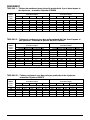
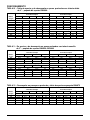
Max. Load Branch Fuse Distance in Feet from Motor to Supply
Model Volts Amps Rating Amps* 0 - 100 101 - 200 201 - 300 301 - 400 401 - 500
3PL 115/230 8.8/4.4 15/15 14/14 12/14 10/14 8/14 8/12
5PL 115/230 12.2/6.1 20/15 12/14 10/14 8/14 6/12 6/12
7PL 115/230 14.8/7.4 20/15 12/14 8/14 6/14 6/12 4/10
10PL 115/230 16.2/8.1 25/15 10/14 8/14 6/14 6/12 4/10
10PLS11C 115/230 14.8/7.4 20/15 12/14 8/14 6/14 6/12 4/10
15PLS11C 115/230 16.2/8.1 25/15 10/14 8/14 6/14 6/12 4/10
WIRING CHART – RECOMMENDED WIRE AND FUSE SIZES
* Time delay fuse or circuit breakers are recommended in any motor circuit.

6. After the pump has built up pressure in the system and
shut off, check the pressure switch operation by opening
a faucet or two and running enough water out to bleed
off pressure until the pump starts. The pump should start
when pressure drops to 30 psi and stop when pressure
reaches 50 psi. Run the pump through one or two
complete cycles to verify correct operation. This will also
help clean the system of dirt and scale dislodged during
installation.
If you were unsuccessful, please refer to the
Troubleshooting section (Page 10) or call our
customer service technical staff.
Preparing to Start the Pump –
Shallow Well
Never run pump dry. Running pump without
water may cause pump to overheat, damaging seal and
possibly causing burns to persons handling pump. Fill pump
with water before starting.
Never run pump against closed discharge.
To do so can boil water inside pump, causing hazardous
pressure in unit, risk of explosion and possibly scalding
persons handling pump.
1. Open the control valve as far as possible (See Figure
16). Then remove the priming plug from the pump and fill
the pump, fill all piping between the pump and the well,
and make sure that all piping in the well is full. If you
have also installed a priming tee in the suction piping,
remove the plug from the tee and fill the suction piping.
2. Replace all fill plugs. Leave the control valve open (in a
shallow well installation, the control valve always stays
open).
3. Power on! Start the pump. The pump should pump water
in two or three minutes.
4. If you don’t have water after 2 or 3 minutes, stop the
pump and remove the fill plugs. Refill the pump and
piping. You may have to repeat this two or three times
in order to get all the trapped air out of the piping. The
control valve remains open throughout this procedure.
5. After the pump has built up pressure in the system and
shut off, check the pressure switch operation by
opening a faucet or two and running enough water out
to bleed off pres sure until the pump starts. The pump
should start when pressure drops to 30 psi and stop
when pressure reaches 50 psi. Run the pump through
one or two complete cycles to verify correct operation.
This will also help clean the system of dirt and scale
dislodged during installation.
If you were unsuccessful, please refer to the
Troubleshooting section (Page 10) or call our
customer service technical staff.
10
Open control
valve as far as
possible and
fill pump and
piping through
priming port
or priming tee.
284 0395 NF
Figure 16 – Open Control Valve

11
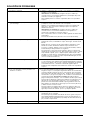
TROUBLESHOOTING CHART
Symptoms Things to Do:
A. Motor will not run. A. Check that the disconnect switch is ON and that the circuit breaker
has not tripped or the fuse has not blown.
DISCONNECT POWER and make sure that wires connecting motor to
power supply and pressure switch are tight and correctly connected
(see Page 7).
If the remedies above do not solve the problem, call your well
professional.
B. Motor runs hot and overload trips. B. Turn to electrical instructions on Page 7 and verify that motor is
correctly wired.
Check with the power company or hydro authority to make sure
that the voltage at the pump is within + 10% of the motor’s rated
nameplate voltage.
DISCONNECT POWER and make sure that the wires connecting the
motor to the power supply are sized according to Wiring Chart, Page 7.
If not, rewire according to the instructions on Page 7.
If the pump is cycling too frequently, see Section E, below.
C. Motor runs but no water is delivered. C. FIRST, check the prime; that is, make sure that the pump and all the
suction piping plus the piping in the well are full of water. If they
aren’t, fill them up.
In cold weather, make sure that the pipes and pump are not frozen.
If they are, thaw them, watching out for split pipes and fittings as you
work. Heat the pump pit or pump house and bury all piping below
the frost line.
Other possible causes (call your pump professional if you suspect one
of these): Air leaks in the suction line, dropping water level in the well,
foot valve stuck or plugged, ejector plugged, impeller plugged, foot
valve or strainer stuck in the mud in the bottom of the well, a shallow
well pump installed on a well with more than 25 ft depth to water
(in this case a deep well jet pump is needed).
D. Pump does not deliver water to full capacity. D. Possible causes are: the well water level is lower than estimated,
making a different nozzle/venturi combination necessary; steel piping
(if used) is corroded or limed, restricting capacity and increasing
friction; or the piping is too small for the installation. Consult your
well professional for any of these conditions.
E. Pump cycles too frequently or does not shut E. Make sure no faucets have been left open.
off at all. If system has a standard tank, make sure it isn’t waterlogged. If it is,
drain it down to the level of the air volume control. Make sure the
AVC isn’t defective and that there are no leaks at any connections.
If system has a precharged tank, disconnect power, open all system
faucets and bleed all pressure off of tank. Use a tire gauge to check
the air pressure in the tank. This should be lower than the cut-in setting
of the pressure switch by 2 PSI (that is, if the pressure switch starts the
pump at 30 PSI, the precharge should be 28 PSI). Check the air valve
for leaks (use a soap solution) and replace the core if necessary.
If you suspect any of the following conditions, consult your well
professional: leaky pipes, leaky foot valve, water level in the well
lower than estimated, clogged ejector or impeller.
F. Air spurts from faucets. F. Pump may still be priming; when priming is complete all air will have
been ejected from the system.
If you suspect leaks in the suction piping, gasses in the well, or that the
pump is intermittently overpumping the well (that is, drawing the water
level down below the foot valve), consult your well professional.
G. Pump leaks around clamp. G. Tighten clamp nut 1-2 turns. Do not overtighten.

1
2
3
4
5
6
7
8
9
11
12
18
16
15
19
21
22
23
24
25
26
20
10
13
14
17
1171 0794
12
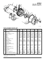
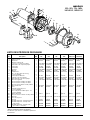
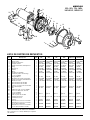
REPLACEMENT PARTS LIST
* Standard hardware item, purchase locally.
• Not shown and not included. Order separately.
** Not illustrated.
MODELS
3PL, 5PL, 7PL, 10PL,
10PLS11C, 15PLS11C
Key
No. Description Qty. 3PL 5PL 7PL 10PL 10PLS11C 15PLS11C
1 Motor 1 A100BHL A100CHL A100DHL A100EHL A100ELL A100FLL
2 Water slinger 1 17351-0009 17351-0009 17351-0009 17351-0009 17351-0009 17351-0009
3 Pressure gauge 1 U239-3 U239-3 U239-3 U239-3 U239-3 U239-3
4 1/2 x 1/8” NPT Reducer bushing 1 U78-107PT U78-107PT U78-107PT U78-107PT U78-107PT U78-107PT
5 Pump body, back half 1 L176-47P L176-47P L176-47P L176-47P L176-47P L176-47P
6 O-ring 1 U9-399 U9-399 U9-399 U9-399 U9-399 U9-399
7 Shaft seal 1 U109-6A U109-6A U109-6A U109-6A U109-6A U109-6A
8 Impeller 1 J105-40PE J105-42PT J105-8PAN J105-22PA J105-8PAN J105-22PA
9 Diffuser 1 J1-39P J1-39P J1-40P J1-40PA J1-40P J1-40PA
** Lockwasher 5 U43-21SS U43-21SS U43-21SS U43-21SS U43-21SS U43-21SS
10 #8 - 32 x 7/8” lg. Screw, S.S. 5 * * * * * *
11 Diffuser O-ring 1 U9-199 U9-199 U9-199 U9-199 U9-199 U9-199
12 Pump body clamp 1 C19-54SS C19-54SS C19-54SS C19-54SS C19-54SS C19-54SS
13 Pump body, front half 1 L76-37P L76-37P L76-37P L76-37P L76-37P L76-37P
14 Control valve 1 L162-10PS L162-10PS L162-10PS L162-10PS L162-10PS L162-10PS
15 1/8” NPT Pipe plug 1 * * * * * *
16 1/4” NPT Pipe plug 1 * * * * * *
17 1/4” NPT straight barbed fitting 1 * * * * * *
18 Switch tube 1 U37-671P U37-671P U37-671P U37-671P U37-671P U37-671P
19 Base 1 C4-42P C4-42P C4-42P C4-42P C4-42P C4-42P
20 5/16” Washer, S.S. 4 * * * * * *
21 5/16” - 18 Hex head nut, S.S. 4 * * * * * *
22 Motor pad 1 C35-11 C35-11 C35-11 C35-11 C35-11 C35-11
23 1/4” NPT Elbow barbed fitting 1 * * * * * *
24 Pressure switch 1 U217-1216 U217-1216 U217-1216 U217-1217 U217-1216 U217-1217
25 1/2” Locknut 1 * * * * * *
26 Connector 1 L43-5C L43-5C L43-5C L43-5C L43-5C L43-5C
• Ejector Kit – Shallow well 1 BK4875 BK4875 BK4875 BK4875 BK4875 BK4875
• Ejector Kit – Deep well (4” dia. well) 1 BK4800 BK4800 BK4800 BK4800 BK4800 BK4800
• Ejector Kit – Deep well (2” single pipe well) 1 BK4840 BK4840 BK4840 BK4840 BK4840 BK4840

13
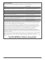
Limited Warranty
BERKELEY warrants to the original consumer purchaser (“Purchaser” or “You”) of the products listed below, that they will be free
from defects in material and workmanship for the Warranty Period shown below.
Product Warranty Period
Water Systems:
Water Systems Products — jet pumps, small centrifugal pumps, submersible pumps and
related accessories
whichever occurs first:
12 months from date of original installation, or
18 months from date of manufacture
Pro-Source
®
Composite Tanks 5 years from date of original installation
Pro-Source
®
Steel Pressure Tanks 5 years from date of original installation
Pro-Source
®
Epoxy-Lined Tanks 3 years from date of original installation
Sump/Sewage/Effluent Products
12 months from date of original installation, or
18 months from date of manufacture
Agricultural/Commer
cial:
Centrifugals – close-coupled motor drive, frame mount, SAE mount, engine drive, VMS, SSCX,
SSHM, solids handling, submersible solids handling
12 months from date of original installation, or
24 months from date of manufacture
Submersible T
urbines, 6” diameter and larger
12 months from date of original installation, or
24 months from date of manufacture
Our limited warranty will not apply to any product that, in our sole judgement, has been subject to negligence, misapplication,
improper installation, or improper maintenance. Without limiting the foregoing, operating a three phase motor with single phase
power through a phase converter will void the warranty. Note also that three phase motors must be protected by three-leg,
ambient compensated, extra-quick trip overload relays of the recommended size or the warranty is void.
Your only remedy, and BERKELEY’s only duty, is that BERKELEY repair or replace defective products (at BERKELEY’s choice). You
must pay all labor and shipping charges associated with this warranty and must request warranty service through the installing
dealer as soon as a problem is discovered. No request for service will be accepted if received after the Warranty Period has
expired. This warranty is not transferable.
BERKELEY SHALL NOT BE LIABLE FOR ANY CONSEQUENTIAL, INCIDENTAL, OR CONTINGENT DAMAGES WHATSOEVER.
THE FOREGOING LIMITED WARRANTIES ARE EXCLUSIVE AND IN LIEU OF ALL OTHER EXPRESS AND IMPLIED WARRANTIES,
INCLUDING BUT NOT LIMITED TO IMPLIED WARRANTIES OF MERCHANTABILITY AND FITNESS FOR A PARTICULAR
PURPOSE. THE FOREGOING LIMITED WARRANTIES SHALL NOT EXTEND BEYOND THE DURATION PROVIDED HEREIN.
Some states do not allow the exclusion or limitation of incidental or consequential damages or limitations on the duration of an
implied warranty, so the above limitations or exclusions may not apply to You. This warranty gives You specific legal rights and You
may also have other rights which vary from state to state.
This Limited Warranty is effective June 1, 2011 and replaces all undated warranties and warranties dated before June 1, 2011.
In the U.S.: BERKELEY, 293 Wright St., Delavan, WI 53115
In Canada: 269 Trillium Dr., Kitchener, Ontario N2G 4W5
Page is loading ...
Page is loading ...
Page is loading ...
Page is loading ...
Page is loading ...
Page is loading ...
Page is loading ...
Page is loading ...
Page is loading ...
Page is loading ...
Page is loading ...
Page is loading ...
Page is loading ...
Page is loading ...
Page is loading ...
Page is loading ...
Page is loading ...
Page is loading ...
Page is loading ...
Page is loading ...
Page is loading ...
Page is loading ...
Page is loading ...
Page is loading ...
Page is loading ...
Page is loading ...
Page is loading ...
-
 1
1
-
 2
2
-
 3
3
-
 4
4
-
 5
5
-
 6
6
-
 7
7
-
 8
8
-
 9
9
-
 10
10
-
 11
11
-
 12
12
-
 13
13
-
 14
14
-
 15
15
-
 16
16
-
 17
17
-
 18
18
-
 19
19
-
 20
20
-
 21
21
-
 22
22
-
 23
23
-
 24
24
-
 25
25
-
 26
26
-
 27
27
-
 28
28
-
 29
29
-
 30
30
-
 31
31
-
 32
32
-
 33
33
-
 34
34
-
 35
35
-
 36
36
-
 37
37
-
 38
38
-
 39
39
-
 40
40


Ask a question and I''ll find the answer in the document
Finding information in a document is now easier with AI
in other languages
Related papers
-
Berkeley 5PNP15H Shallow Well Water System Owner's manual
-
-
Pentair BPD Series Corrosion Resistant Self-Priming Centrifugal Pump Owner's manual
-
-
-
-
-
-
-
Other documents
-
STA-RITE CJ Series Owner's manual
-
Little GIANT JPC-100-C User manual
-
Eco Flo EFCWJ5 Installation guide
-
red lion RL-SWJ Series Owner's manual
-
Pentair ST.E.P. PLUS D 20DOM05121+1 Owner's manual
-
Craftsman 390.253251 Owner's manual
-
 Utilitech 148013 User guide
-
Everbilt J100A3 FAQ
-
-
