Page is loading ...

Panasonic Corporation
1006 Kadoma, Kadoma City, Osaka, Japan
85464609141021
Operating Instructions
Air Conditioner
Model No.
Indoor Units
CASSETTE
CEILING-MOUNTED
WALL-MOUNTED
CONCEALED DUCT
(4-WAY: U1 type)
S-22MU1E5
S-28MU1E5
S-36MU1E5
S-45MU1E5
S-56MU1E5
S-73MU1E5
S-106MU1E5
S-140MU1E5
S-160MU1E5
(1-WAY: D1 Type)
S-28MD1E5
S-36MD1E5
S-45MD1E5
S-56MD1E5
S-73MD1E5
(T1 Type)
S-36MT1E5
S-45MT1E5
S-56MT1E5
S-73MT1E5
S-106MT1E5
S-140MT1E5
(K1 Type)
S-22MK1E5
S-28MK1E5
S-36MK1E5
S-45MK1E5
S-56MK1E5
S-73MK1E5
S-106MK1E5
(Slim Low Static)
(M1 Type)
S-22MM1E5
S-28MM1E5
S-36MM1E5
S-45MM1E5
S-56MM1E5
(Low Silhouette)
(F1 Type)
S-22MF1E5
S-28MF1E5
S-36MF1E5
S-45MF1E5
S-56MF1E5
S-73MF1E5
S-90MF1E5
S-106MF1E5
S-140MF1E5
S-160MF1E5
(High Static Pressure)
(E1 Type)
S-73ME1E5
S-106ME1E5
S-140ME1E5
S-224ME1E5
S-280ME1E5
FLOOR STANDING
CONCEALED
FLOOR STANDING
(4-WAY: Y1 Type)
S-22MY1E5
S-28MY1E5
S-36MY1E5
S-45MY1E5
S-56MY1E5
(2-WAY: L1 Type)
S-22ML1E5
S-28ML1E5
S-36ML1E5
S-45ML1E5
S-56ML1E5
S-73ML1E5
(P1 Type)
S-22MP1E5
S-28MP1E5
S-36MP1E5
S-45MP1E5
S-56MP1E5
S-71MP1E5
(R1 Type)
S-22MR1E5
S-28MR1E5
S-36MR1E5
S-45MR1E5
S-56MR1E5
S-71MR1E5
Outdoor Units
Mini VRF U-4LE1E5, U-5LE1E5, U-6LE1E5
U-4LE1E8, U-5LE1E8, U-6LE1E8
This air conditioner uses the refrigerant R410A.
Before operating the unit, read these operating instructions thoroughly and
keep them for future reference.
OI-85464609141021_COVER.fm Page 2 Tuesday, August 2, 2011 12:38 PM

2
Contents
Page
Product Information .......................................................................................................................2
Alert Symbols ................................................................................................................................2
Installation Location.......................................................................................................................3
Electrical Requirements ................................................................................................................3
Safety Instructions.........................................................................................................................4
Wireless Remote Controller (Optional parts) ................................................................................5
NOTE Refer to the Operating Instructions attached to the optional Wireless Remote
Controller. ....................................................................................................................5
Timer Remote Controller (Optional parts) .....................................................................................5
NOTE Refer to the Operating Instructions attached to the optional Timer Remote
Controller. ....................................................................................................................5
Operation Condition ......................................................................................................................5
Adjusting the Airflow Direction.......................................................................................................6
Adjusting the Airflow Direction for Multiple Indoor Units Using a Single Remote Controller
(Wired)...........................................................................................................................................8
Special Remarks ...........................................................................................................................9
Care and Cleaning ........................................................................................................................9
Specifications ............................................................................................................................112
Product Information
If you have problems or questions concerning your Air Conditioner, you will need the following
information. Model and serial numbers are on the nameplate on the bottom of the cabinet.
Model No. _________________________________ Serial No. _______________________
Date of purchase______________________________________________________________
Dealer’s address ______________________________________________________________
Phone number________________________________________________________________
Alert Symbols
The following symbols used in this manual, alert you to potentially dangerous conditions
to users, service personnel or the appliance:
This symbol refers to a hazard or unsafe practice
which can result in severe personal injury or
death.
This symbol refers to a hazard or unsafe practice
which can result in personal injury or product or
property damage.
OI-141-2-EN
01_85464609141021_EN.fm Page 2 Thursday, August 11, 2011 11:24 AM

3
Installation Location
• We recommend that this air conditioner be installed properly by qualified installation
technicians in accordance with the Installation Instructions provided with the unit.
• Before installation, check that the voltage of the electric supply in your home or office is the
same as the voltage shown on the nameplate.
Electrical Requirements
1. All wiring must conform to the local electrical codes. Consult your dealer or a qualified
electrician for details.
2. Each unit must be properly grounded with a ground (or earth) wire or through the supply
wiring.
3. Wiring must be done by a qualified electrician.
The wires in this mains lead are colored in accordance with the following code:
Green-and-Yellow: Earth
Blue: Neutral
Brown: Live
As the colors of the wires in the mains lead of this appliance may not correspond with the colored
markings identifying the terminals in your plugs, proceed as follows:
The wire which is colored green and yellow must be connected to the terminal in the plug which
is marked by the letter E or by the safety earth symbol or colored green or green-and-yellow.
The wire which is colored blue must be connected to the terminal which is marked with letter N or
colored black.
The wire which is colored brown must be connected to the terminal which is marked with the
letter L or colored red.
• Do not install this air conditioner where there are fumes or flammable gases, or in an
extremely humid space such as a greenhouse.
• Do not install the air conditioner where excessively high heat-generating objects
are placed.
Avoid: To protect the air conditioner from heavy corrosion, avoid installing the outdoor unit where
salty sea water can splash directly onto it or in sulphurous air near a spa.
To warm up the system, the power mains must be turned on
at least five (5) hours before operation. Leave the power
mains ON unless you will not be using this appliance for an
extended period.
Pull off the power plug from a receptacle, or switch off the breaker, or switch off the power
disconnecting mean to isolate the air conditioner from the main power supply when not in use
for a long time.
Power mains
ON
NOTE
OI-141-3-EN
01_85464609141021_EN.fm Page 3 Thursday, August 11, 2011 11:24 AM

4
Safety Instructions
• Read these Operating Instructions carefully before using this air conditioner. If you still
have any difficulties or problems, consult your dealer for help.
• This air conditioner is designed to give you comfortable room conditions. Use this only
for its intended purpose as described in these Operating Instructions.
• Confirm to authorized dealer or specialist on usage of specified refrigerant type.
Using of refrigerant other than the specified type may cause product damage, burst
and injury etc.
• Never touch the unit with wet hands.
• Never use or store gasoline or other flammable vapor or liquid near the air
conditioner — it is very dangerous.
• Do not use this appliance in a potentially explosive atmosphere.
• This air conditioner has no ventilator for intaking fresh air from outdoors. You must
open doors or windows frequently when you use gas or oil heating appliances in
the same room, which consume a lot of oxygen from the air. Otherwise there is a
risk of suffocation in an extreme case.
• Provide a power outlet to be used exclusively for each unit, and a power supply
disconnect, circuit breaker and earth leakage breaker for overcurrent protection
should be provided in the exclusive line.
• Provide a power outlet exclusively for each unit, and full disconnection means
having a contact separation in all poles must be incorporated in the fixed wiring in
accordance with the wiring rules.
• To prevent possible hazards from insulation failure, the unit must be
grounded.
• Do not clean inside the indoor and outdoor units by users. Engage authorized
dealer or specialist for cleaning.
• In case of malfunction of this appliance, do not repair by yourself. Contact to the
sales dealer or service dealer for a repair.
• Refrigerant gas leakage may cause fire.
• For safety, be sure to turn the air conditioner off and also to disconnect
the power before cleaning or servicing.
• Pull off the power plug from a receptacle, or switch off the breaker, or
switch off the power disconnecting mean to isolate the air conditioner from the
main power supply in case of emergency.
• Do not turn the air conditioner on and off from the power mains switch. Use the ON/
OFF operation button.
• Do not stick anything into the air outlet of the outdoor unit.
This is dangerous because the fan is rotating at high speed.
• Do not touch the air inlet or the sharp aluminum
fins of the outdoor unit. You may get injured.
• Keep the fire alarm and the air outlet at least 1.5m away from the unit.
• This appliance is not intended for use by persons(including children) with reduced
physical, sensory or mental capabilities, or lack of experience and knowledge,
unless they have been given supervision or instruction concerning use of the
appliance by a person responsible for their safety. Children should be supervised to
ensure that do not play with the appliance.
• Do not cool or heat the room too much if babies or invalids are present.
• Do not sit or step on the unit.
You may fall down accidentally.
• Do not stick any object
into the FAN CASE.
You may be injured and
the unit may be damaged.
• The compressor may occasionally stop during thunderstorms.
This is not a mechanical failure. The unit automatically recovers after a few minutes.
• The English text is the original instructions. Other languages are translation of the
original instructions.
NOTICE
OI-141-4-EN
01_85464609141021_EN.fm Page 4 Thursday, August 11, 2011 11:24 AM

5
Wireless Remote Controller (Optional parts)
Timer Remote Controller (Optional parts)
Operation Condition
Refer to the Operating Instructions attached to the optional Wireless Remote Controller.
Refer to the Operating Instructions attached to the optional Timer Remote Controller.
Use this air conditioner under the following temperature range.
Indoor temperature range:
Cooling mode 14°C ~ 25°C (*WBT) / 18°C ~ 32°C (*DBT)
Heating mode 16°C ~ 30°C (*DBT)
Outdoor temperature range:
Cooling mode -10°C ~ 46°C (*DBT)
Heating mode -20°C ~ 18°C (*WBT) / -20°C ~ 24°C (*DBT)
*DBT: Dry bulb temperature
*WBT: Wet bulb temperature
NOTE
NOTE
OI-141-5-EN
01_85464609141021_EN.fm Page 5 Thursday, August 11, 2011 11:24 AM

6
Adjusting the Airflow Direction
The functions differ depending on the indoor unit used. The airflow direction cannot be set
using the remote controller for any unit which is not listed below.
U1 type, Y1 type, L1 type, D1 type, T1 type and K1 type.
• Never use your hands to move the flap (vertical airflow flap) that is controlled using the
remote controller.
• When the air conditioner is turned off, the flap (vertical airflow flap) automatically moves to
the downward position.
• The flap (vertical airflow flap) moves to the upward position when performing the standby
operation for heating. The swing operation is made after the standby operation for heating is
released, but swing is indicated on the remote controller even during the standby operation
for heating.
Setting the airflow
direction
The airflow direction changes each time the FLAP button is pressed during operation.
To activate the swing
operation
Press the FLAP button to set the flap (vertical airflow flap) to the downward position, and then
press the FLAP button again. This displays , and the airflow automatically swings up and
down.
To stop the swing
operation
Press the FLAP button again during the flap swing operation to stop the flap at the desired
position. Then, the airflow can be set from the top position by pressing the FLAP button again.
Indicator when swing operation is stopped
During cooling or drying operation, the flap will not stop at the downward position. Even if the
flap is stopped at the downward position during the swing operation, it will not stop until it
moves to the third position from the top.
Heating Cooling and drying Fan operation All operations
Set the flap (vertical airflow flap) to the downward
position. If the flap is set to the upward position,
the warm air may not reach the floor.
The flap (vertical airflow flap) can
be set to one of three positions.
Initial setting
Initial setting
Initial setting
Continuous
operation
Fan and heating Cooling and drying
OI-141-6-EN
01_85464609141021_EN.fm Page 6 Thursday, August 11, 2011 11:24 AM

7
Adjusting the Airflow Direction (continued)
U1 type, Y1 type, L1 type and D1 type air conditioners are equipped with auto flaps.
You can set the airflow direction to a specific angle or to the sweep mode using the remote
controller.
Do not move the flap with your hands.
4-way (U1 type), (Y1 type) • The air outlet flap can be easily removed and washed with water.
• Be sure to always stop operation before removing the flap.
• After washing with water, allow it to dry, and then remount it with the arrow facing outward.
Ceiling mounted type (T1)
Vertical directions (automatic)
This air conditioner is equipped with an auto flap. You can set the airflow direction to a specific
angle or to the sweep mode using the remote controller. (Refer to the description of the remote
controller.)
Do not move the flap with your hands.
Horizontal directions (manual)
The horizontal airflow direction can be adjusted manually by moving the vertical vanes to the
left or right.
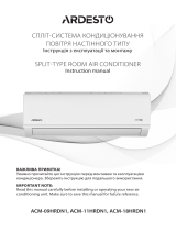
Wall mounted type (K1)
Vertical directions (automatic)
Confirm that the remote controller has been turned on. Press the FLAP button to start the flap
moving up and down. If you want to stop the flap movement and to direct the air in the desired
direction, press the FLAP button again. In the cool mode, do not direct the flap down and move
out of the cooling zone “A”, otherwise, condensation may drip on to the floor. Zone ‘‘A’’ is the
recommended flap position for cooling.
When operating continuously in the fixed airflow direction setting for about an hour, the airflow
direction is automatically controlled and the flap position is changed. The airflow direction may
be different from the display on the remote controller.
Do not move the flap with your hands.
Horizontal directions (manual)
The horizontal airflow direction can be adjusted manually by moving the vertical vanes to the
left or right.
Concealed duct type (F1, M1, E1)
This air conditioner is not equipped with air outlet parts. These must be obtained locally. Please
refer to the manual of the locally adopted air outlet parts.
Indoor unit
Zone ‘‘B’’ for
heating
Zone
‘‘A’’ for
cooling
OI-141-7-EN
01_85464609141021_EN.fm Page 7 Thursday, August 11, 2011 11:24 AM

8
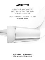
Adjusting the Airflow Direction for Multiple Indoor Units
Using a Single Remote Controller (Wired)
• The airflow direction cannot be set using the remote controller for the concealed duct type
(F1, M1, E1) and floor standing type (P1, R1).
• If multiple indoor units are connected to a remote controller, the airflow direction can be set
for each indoor unit by selecting the indoor units (see the operation below).
Auto Flap ( ) button
• To set the airflow for individual units, press the UNIT button. Display shows the indoor unit
number under group control. Set the airflow direction for the indoor unit that is shown on the
display.
• Each time UNIT is pressed, the indicator changes in the order shown below.
• When nothing is displayed, you can make the setting for all indoor units in one operation.
• The unit number is displayed as Outdoor Unit Number–Indoor Unit Number. It varies
depending on the number of units under group control.
One outdoor unit and eight indoor units Two outdoor units and four indoor units
No display
Unit No.
1–1
Unit No.
1–2
Unit No.
1–3
Unit No.
1–8
No
display
Unit
No.
1–1
Unit
No.
1–2
Unit
No.
1–3
Unit
No.
2–4
Unit
No.
1–4
Unit
No.
2–1
OI-141-8-EN
01_85464609141021_EN.fm Page 8 Thursday, August 11, 2011 11:24 AM

9
Special Remarks
Care and Cleaning
How it works • Once the room temperature reaches the level that was set, the unit repeats the cycle of
turning on and off automatically.
• In order to prevent the humidity in the room from rising again, the indoor fan also turns off
when the unit stops operating.
• The fan speed is set to ‘‘LO.’’ automatically, and cannot be adjusted.
• ‘‘DRY’’ operation is not possible if the outdoor temperature is 15 °C or less.
Heating performance • Because this appliance heats a room by utilizing the heat of the outside air (heat pump
system), the heating efficiency will fall off when the outdoor temperature is very low. If
sufficient heat cannot be obtained with this heat pump, use another heating appliance in
conjunction with this unit.
Defrosting • When the outdoor temperature is low, frost or ice may form on the outdoor heat exchanger
coil, reducing the heating performance. When this happens, a microcomputer-controlled
defrosting system operates. At the same time, the fan on the indoor unit stops (or runs at
very low speed in some cases) and the ‘‘STANDBY’’ indicator appears on the display until
defrosting is completed. Heating operation then restarts after several minutes. (This interval
will vary slightly depending upon the outdoor temperature and the way in which frost forms.)
(standby) on the
display
• For several minutes after the start of heating operation, the indoor fan will not start running
(or it will run at very low speed in some cases) until the indoor heat exchanger coil has
warmed up sufficiently. This is because a cold draft prevention system is operating. During
this period, the ‘‘ ’’ (standby) indicator remains displayed.
• ‘‘ ’’ (standby) remains displayed during defrosting or when the compressor has been
turned off (or when the unit is running at very low speed) by the thermostat when the
system is in the heating mode.
• Upon completion of defrosting and when the compressor is turned on again, ‘‘ ’’
(standby) will turn off automatically as heating operation resumes.
Should the power fail while the unit is running
If the power supply for this unit is temporarily cut off, the unit will automatically resume
operation (once the power is restored) using the same settings before the power was cut off.
1. For safety, be sure to turn the air conditioner off and also to disconnect the power
before cleaning.
2. Do not pour water on the indoor unit to clean it. This will damage the internal
components and cause an electric shock hazard.
Air intake and outlet side
(Indoor unit)
Clean the air intake and outlet side of the indoor unit with a vacuum cleaner brush, or wipe
them with a clean, soft cloth.
If these parts are stained, use a clean cloth moistened with water. When cleaning the air outlet
side, be careful not to force the vanes out of place.
1. Never use solvents or harsh chemicals when cleaning the indoor unit. Do not wipe
plastic parts using very hot water.
2. Some metal edges and the fins are sharp and may cause injury if handled
improperly; be especially careful when you clean these parts.
3. The internal coil and other components of the outdoor unit must be cleaned
periodically. Consult your dealer or service center.
‘‘DRY’’ Operation
Heating Operation
NOTE
OI-141-9-EN
01_85464609141021_EN.fm Page 9 Thursday, August 11, 2011 11:24 AM

10
Safety Instructions
Stop using the product when any abnormality/failure occurs and
disconnect the power plug.
(Risk of smoke/fire/electric shock)
Examples of
abnormality/
failure
- The product sometimes does not start when turned on.
- The power is sometimes disconnected when the cord is moved.
- Burnt odor or abnormal noise is detected during operation.
- The body is deformed or abnormally hot.
Contact immediately your local dealer for maintenance/repair.
Information for Users on Collection and Disposal of Old Equipment and Used Batteries
These symbols on the products, packaging, and/or accompanying documents mean that used electrical and
electronic products and batteries should not be mixed with general household waste.
For proper treatment, recovery and recycling of old products and used batteries, please take them to
applicable collection points, in accordance with your national legislation and the Directives 2002/96/EC and
2006/66/EC.
By disposing of these products and batteries correctly, you will help to save valuable resources and prevent
any potential negative effects on human health and the environment which could otherwise arise from
inappropriate waste handling.
For more information about collection and recycling of old products and batteries, please contact your local
municipality, your waste disposal service or the point of sale where you purchased the items.
Penalties may be applicable for incorrect disposal of this waste, in accordance with national legislation.
For business users in the European Union
If you wish to discard electrical and electronic equipment, please contact your dealer or supplier for further
information.
[Information on Disposal in other Countries outside the European Union]
These symbols are only valid in the European Union. If you wish to discard these items, please contact your
local authorities or dealer and ask for the correct method of disposal.
Note for the battery symbol (bottom two symbol examples):
This symbol might be used in combination with a chemical symbol. In this case it complies with the requirement
set by the Directive for the chemical involved.
Pb
To be followed absolutely
OI-141-10-EN
01_85464609141021_EN.fm Page 10 Thursday, August 11, 2011 11:24 AM

11
OI-141-1-FR
Mode d’emploi
Climatiseur
N° de modèle
Unités intérieures
CASSETTE
MONTE AU
PLAFOND
MONTE AU MUR
CONDUIT
CACHE
(4 VOIES : Type U1)
S-22MU1E5
S-28MU1E5
S-36MU1E5
S-45MU1E5
S-56MU1E5
S-73MU1E5
S-106MU1E5
S-140MU1E5
S-160MU1E5
(1 VOIE : Type D1)
S-28MD1E5
S-36MD1E5
S-45MD1E5
S-56MD1E5
S-73MD1E5
(Type T1)
S-36MT1E5
S-45MT1E5
S-56MT1E5
S-73MT1E5
S-106MT1E5
S-140MT1E5
(Type K1)
S-22MK1E5
S-28MK1E5
S-36MK1E5
S-45MK1E5
S-56MK1E5
S-73MK1E5
S-106MK1E5
(Mince Faible
Statique)
(Type M1)
S-22MM1E5
S-28MM1E5
S-36MM1E5
S-45MM1E5
S-56MM1E5
(Silhouette Basse)
(Type F1)
S-22MF1E5
S-28MF1E5
S-36MF1E5
S-45MF1E5
S-56MF1E5
S-73MF1E5
S-90MF1E5
S-106MF1E5
S-140MF1E5
S-160MF1E5
(Haute Pression
Statique)
(Type E1)
S-73ME1E5
S-106ME1E5
S-140ME1E5
S-224ME1E5
S-280ME1E5
VERTICAL AU
SOL
VERTICAL AU
SOL CACHE
(4 VOIES : Type Y1)
S-22MY1E5
S-28MY1E5
S-36MY1E5
S-45MY1E5
S-56MY1E5
(2 VOIES : Type L1)
S-22ML1E5
S-28ML1E5
S-36ML1E5
S-45ML1E5
S-56ML1E5
S-73ML1E5
(Type P1)
S-22MP1E5
S-28MP1E5
S-36MP1E5
S-45MP1E5
S-56MP1E5
S-71MP1E5
(Type P1)
S-22MR1E5
S-28MR1E5
S-36MR1E5
S-45MR1E5
S-56MR1E5
S-71MR1E5
Unités extérieures
Mini VRF U-4LE1E5, U-5LE1E5, U-6LE1E5
U-4LE1E8, U-5LE1E8, U-6LE1E8
Ce climatiseur utilise le frigorigène R410A.
Avant d’utiliser l’appareil, lisez ce mode d’emploi dans son intégralité et
conservez-le pour toute référence ultérieure.
02_85464609141021_FR_Cover.fm Page 11 Tuesday, August 2, 2011 12:50 PM

41
OI-141-1-IT
Istruzioni per l’uso
Condizionatore d’aria
No. del modello
Unità interne
A CASSETTA
CON MONTAGGIO
A SOFFITTO
CON MONTAGGIO
A PARETE
A CONDOTTO
NASCOSTO
(A 4 VIE: tipo U1)
S-22MU1E5
S-28MU1E5
S-36MU1E5
S-45MU1E5
S-56MU1E5
S-73MU1E5
S-106MU1E5
S-140MU1E5
S-160MU1E5
(A 1 VIA: tipo D1)
S-28MD1E5
S-36MD1E5
S-45MD1E5
S-56MD1E5
S-73MD1E5
(Tipo T1)
S-36MT1E5
S-45MT1E5
S-56MT1E5
S-73MT1E5
S-106MT1E5
S-140MT1E5
(Tipo K1)
S-22MK1E5
S-28MK1E5
S-36MK1E5
S-45MK1E5
S-56MK1E5
S-73MK1E5
S-106MK1E5
(Sottile a bassa
pressione statica)
(Tipo M1)
S-22MM1E5
S-28MM1E5
S-36MM1E5
S-45MM1E5
S-56MM1E5
(A profilo basso)
(Tipo F1)
S-22MF1E5
S-28MF1E5
S-36MF1E5
S-45MF1E5
S-56MF1E5
S-73MF1E5
S-90MF1E5
S-106MF1E5
S-140MF1E5
S-160MF1E5
(Ad alta
pressione statica)
(Tipo E1)
S-73ME1E5
S-106ME1E5
S-140ME1E5
S-224ME1E5
S-280ME1E5
A PAVIMENTO
A PAVIMENTO
NASCOSTO
(A 4 VIE: tipo Y1)
S-22MY1E5
S-28MY1E5
S-36MY1E5
S-45MY1E5
S-56MY1E5
(A 2 VIE: tipo L1)
S-22ML1E5
S-28ML1E5
S-36ML1E5
S-45ML1E5
S-56ML1E5
S-73ML1E5
(Tipo P1)
S-22MP1E5
S-28MP1E5
S-36MP1E5
S-45MP1E5
S-56MP1E5
S-71MP1E5
(Tipo R1)
S-22MR1E5
S-28MR1E5
S-36MR1E5
S-45MR1E5
S-56MR1E5
S-71MR1E5
Unità esterne
Mini VRF U-4LE1E5, U-5LE1E5, U-6LE1E5
U-4LE1E8, U-5LE1E8, U-6LE1E8
In questo condizionatore d’aria viene impiegato il refrigerante R410A.
Prima di utilizzare l’unità, leggere a fondo queste istruzioni per l’uso e
conservarle come riferimento futuro.
05_85464609141021_IT_Cover.fm Page 41 Wednesday, August 3, 2011 9:32 AM

51
OI-141-1-NL
Gebruiksinstructies
Airconditioner
Modelnr.
Binnenunits
CASSETTEMODEL
PLAFONDMODEL
WANDMODEL
VERBORGEN
KANAALMODEL
(4-WEG: type U1)
S-22MU1E5
S-28MU1E5
S-36MU1E5
S-45MU1E5
S-56MU1E5
S-73MU1E5
S-106MU1E5
S-140MU1E5
S-160MU1E5
(1-WEG: type D1)
S-28MD1E5
S-36MD1E5
S-45MD1E5
S-56MD1E5
S-73MD1E5
(Type T1)
S-36MT1E5
S-45MT1E5
S-56MT1E5
S-73MT1E5
S-106MT1E5
S-140MT1E5
(Type K1)
S-22MK1E5
S-28MK1E5
S-36MK1E5
S-45MK1E5
S-56MK1E5
S-73MK1E5
S-106MK1E5
(Slank laag
statisch)
(Type M1)
S-22MM1E5
S-28MM1E5
S-36MM1E5
S-45MM1E5
S-56MM1E5
(Onopvallend
silhouet)
(Type F1)
S-22MF1E5
S-28MF1E5
S-36MF1E5
S-45MF1E5
S-56MF1E5
S-73MF1E5
S-90MF1E5
S-106MF1E5
S-140MF1E5
S-160MF1E5
(Hoge statische
druk)
(Type E1)
S-73ME1E5
S-106ME1E5
S-140ME1E5
S-224ME1E5
S-280ME1E5
VLOERMODEL
VERBORGEN
VLOERMODEL
(4-WEG: type Y1)
S-22MY1E5
S-28MY1E5
S-36MY1E5
S-45MY1E5
S-56MY1E5
(2-WEG: type L1)
S-22ML1E5
S-28ML1E5
S-36ML1E5
S-45ML1E5
S-56ML1E5
S-73ML1E5
(Type P1)
S-22MP1E5
S-28MP1E5
S-36MP1E5
S-45MP1E5
S-56MP1E5
S-71MP1E5
(Type R1)
S-22MR1E5
S-28MR1E5
S-36MR1E5
S-45MR1E5
S-56MR1E5
S-71MR1E5
Buitenunits
Mini VRF U-4LE1E5, U-5LE1E5, U-6LE1E5
U-4LE1E8, U-5LE1E8, U-6LE1E8
Deze airconditioner gebruikt het koelmiddel R410A.
Lees deze gebruiksinstructies goed door voor u het apparaat gebruikt en
bewaar ze voor toekomstig gebruik.
06_85464609141021_NL_Cover.fm Page 51 Tuesday, August 2, 2011 5:04 PM

112
4-Way Cassette (U1 type)
Power Source 220 - 230 - 240 V, single-phase, 50/60 Hz
Model Name
S-22MU1E5 S-28MU1E5 S-36MU1E5 S-45MU1E5 S-56MU1E5 S-73MU1E5
Sound Pressure Level
High
Medium
Cooling Capacity
kW
BTU/h
Heating Capacity
kW
BTU/h
dB(A)
dB(A)
Sound Power Level
Low
High
Medium
dB(A)
dB(A)
dB(A)
Low
dB(A)
Unit Dimensions (H×W×D)
mm
290×950×950
Power Source 220 - 230 - 240 V, single-phase, 50/60 Hz
41 41 41 43
42 42 42 45
44 44 44 47
27 27 27 27
28 28 28 28
29 29 29 30
8,500 11,000 14,000 17,000
2.5 3.2 4.2 5.0
7,500 9,600 12,000 15,000
2.2 2.8 3.6 4.5
44
47
50
27
29
32
21,000
6.3
19,000
5.6
44
48
54
28
31
35
27,000
8.0
25,000
7.3
290×950×950 290×950×950 290×950×950 290×950×950 290×950×950
Net Weight
kg
24
24
Net Weight
kg 29 29
24
29
24 24 25
Net Weight
kg
21
21 21 25 33 33
Model Name S-106MU1E5 S-140MU1E5
Sound Pressure Level
High
Medium
Cooling Capacity
kW
BTU/h
Heating Capacity
kW
BTU/h
dB(A)
dB(A)
Sound Power Level
Low
High
Medium
dB(A)
dB(A)
dB(A)
Low
dB(A)
Unit Dimensions (H×W×D)
mm
353×950×950
47 49
55 55
60 61
43 44
39,000 54,600
11.4 16.0
36,000 47,800
10.6 14.0
353×950×950
S-160MU1E5
50
56
62
45
61,400
18.0
54,600
16.0
32 33
38 39
34
40
353×950×950
Ceiling (T1 type)
Power Source 220 - 230 - 240 V, single-phase, 50/60 Hz
Model Name
S-36MT1E5 S-45MT1E5 S-56MT1E5 S-73MT1E5 S-106MT1E5 S-140MT1E5
Sound Pressure Level
High
Medium
Cooling Capacity
kW
BTU/h
Heating Capacity
kW
BTU/h
dB(A)
dB(A)
Sound Power Level
Low
High
Medium
dB(A)
dB(A)
dB(A)
Low
dB(A)
Unit Dimensions (H×W×D)
mm
210×910×680
41 41 41 44
43 44 44 47
46 47 47 49
30 30 30 33
32 33 33 36
35 36 36 38
14,000 17,000 21,000 27,000
4.2 5.0 6.3 8.0
12,000 15,000 19,000 25,000
3.6 4.5 5.6 7.3
46
49
52
35
38
41
39,000
11.4
36,000
10.6
48
51
54
37
40
43
54,600
16.0
47,800
14.0
210×910×680 210×910×680 210×1180×680 210×1595×680 210×1595×680
Specifications
12_85464609141021_Spec.fm Page 112 Monday, July 25, 2011 3:38 PM

113
High Static Pressure Ducted (E1 type)
Power Source 220 - 230 - 240 V, single-phase, 50/60 Hz
220 - 230 - 240 V,
single-phase, 50 Hz
Model Name
S-73ME1E5 S-106ME1E5 S-140ME1E5 S-224ME1E5 S-280ME1E5
Sound Pressure Level
High
Medium
Cooling Capacity
kW
BTU/h
Heating Capacity
kW
BTU/h
dB(A)
dB(A)
Sound Power Level
Low
High
Medium
dB(A)
dB(A)
dB(A)
Low
dB(A)
Unit Dimensions (H×W×D)
mm
420×1065×620
53 53 55 57
54 55 57 58
55 56 58 59
42 42 44 46
43 44 46 47
44 45 47 48
27,000 39,000 54,600 85,300
8.0 11.4 16.0 25.0
25,000 36,000 47,800 76,400
7.3 10.6 14.0 22.4
60
61
62
49
50
51
107,500
31.5
95,500
28.0
420×1065×620 450×1065×620
467×1428×1230 467×1428×1230
Net Weight
kg 47 50 54 110 120
Net Weight
kg
18.4
18.4 18.4 18.4 18.4
4-Way Cassette 60x60 (Y1 type)
Power Source 220 - 230 - 240 V, single-phase, 50/60 Hz
Model Name S-22MY1E5 S-28MY1E5 S-36MY1E5 S-45MY1E5 S-56MY1E5
Sound Pressure Level
High
Medium
Cooling Capacity
kW
BTU/h
Heating Capacity
kW
BTU/h
dB(A)
dB(A)
Sound Power Level
Low
High
Medium
dB(A)
dB(A)
dB(A)
Low
dB(A)
Unit Dimensions (H×W×D)
mm
313×625×625
41 41 42 45
43 43 46 48
46 46 49 53
25 25 26 28
27 27 29 32
30 30 32 36
8,500 11,000 14,000 17,000
2.5 3.2 4.2 5.0
7,500 9,600 12,000 16,000
2.2 2.8 3.6 4.7
50
54
58
33
37
41
21,000
6.3
19,000
5.6
313×625×625 313×625×625 313×625×625 313×625×625
Net Weight
kg
19
19 19 19 19
Slim Low Static Ducted (M1 type)
Power Source 220 - 230 - 240 V, single-phase, 50/60 Hz
Model Name
S-22MM1E5 S-28MM1E5 S-36MM1E5 S-45MM1E5 S-56MM1E5
Sound Pressure Level
High
Medium
Cooling Capacity
kW
BTU/h
Heating Capacity
kW
BTU/h
dB(A)
dB(A)
Sound Power Level
Low
High
Medium
dB(A)
dB(A)
dB(A)
Low
dB(A)
Unit Dimensions (H×W×D)
mm
200×750×640
40 42 43 45
42 44 45 47
43 45 47 49
25 27 28 30
27 29 30 32
28 30 32 34
8,500 11,000 14,000 17,000
2.5 3.2 4.2 5.0
7,500 9,600 12,000 15,000
2.2 2.8 3.6 4.5
48
50
52
31
33
35
21,000
6.3
19,000
5.6
200×750×640 200×750×640 200×750×640 200×750×640
Specifications
12_85464609141021_Spec.fm Page 113 Monday, July 25, 2011 3:38 PM

114
Low Silhouette Ducted (F1 type)
Power Source 220 - 230 - 240 V, single-phase, 50/60 Hz
Model Name
S-22MF1E5 S-28MF1E5 S-36MF1E5 S-45MF1E5 S-56MF1E5 S-73MF1E5
Sound Pressure Level
High
Medium
Cooling Capacity
kW
BTU/h
Heating Capacity
kW
BTU/h
dB(A)
dB(A)
Sound Power Level
Low
High
Medium
dB(A)
dB(A)
dB(A)
Low
dB(A)
Unit Dimensions (H×W×D)
mm
310×700×630
33 33 33 36
37 37 37 39
40 40 40 41
22 22 22 25
26 26 26 28
29 29 29 30
8,500 11,000 14,000 17,000
2.5 3.2 4.2 5.0
7,500 9,600 12,000 15,000
2.2 2.8 3.6 4.5
36
39
41
25
28
30
21,000
6.3
19,000
5.6
38
41
45
27
30
34
27,000
8.0
25,000
7.3
310×700×630 310×700×630 310×700×630 310×700×630 310×1000×630
Net Weight
kg
24
24 24 25 25 32
Net Weight
kg
30
30 30 30 30 30
2-Way Cassette (L1 type)
Power Source 220 - 230 - 240 V, single-phase, 50/60 Hz
Model Name
S-22ML1E5 S-28ML1E5 S-36ML1E5 S-45ML1E5 S-56ML1E5 S-73ML1E5
Sound Pressure Level
High
Medium
Cooling Capacity
kW
BTU/h
Heating Capacity
kW
BTU/h
dB(A)
dB(A)
Sound Power Level
Low
High
Medium
dB(A)
dB(A)
dB(A)
Low
dB(A)
Unit Dimensions (H×W×D)
mm
358×1060×680
35 37 39 40
38 40 42 44
40 44 45 46
24 26 28 29
27 29 31 33
30 33 34 35
8,500 11,000 14,000 17,000
2.5 3.2 4.2 5.0
7,500 9,600 12,000 15,000
2.2 2.8 3.6 4.5
40
44
46
29
33
35
21,000
6.3
19,000
5.6
44
46
49
33
35
38
27,000
8.0
25,000
7.3
358×1060×680 358×1060×680 358×1060×680 358×1060×680 358×1060×680
Power Source 220 - 230 - 240 V, single-phase, 50/60 Hz
Net Weight
kg 32 47 47
Model Name S-90MF1E5 S-106MF1E5
Sound Pressure Level
High
Medium
Cooling Capacity
kW
BTU/h
Heating Capacity
kW
BTU/h
dB(A)
dB(A)
Sound Power Level
Low
High
Medium
dB(A)
dB(A)
dB(A)
Low
dB(A)
Unit Dimensions (H×W×D)
mm
310×1000×630
38 42
41 44
45 49
34 38
34,000 39,000
10.0 11.4
30,000 36,000
9.0 10.6
310×1480×630
S-140MF1E5
44
48
51
40
54,600
16.0
47,800
14.0
27 31
30 33
33
37
310×1480×630
47
S-160MF1E5
44
48
51
40
61,500
18.0
54,600
16.0
33
37
310×1480×630
Specifications
12_85464609141021_Spec.fm Page 114 Monday, July 25, 2011 3:38 PM

115
1-Way Cassette (D1 type)
Power Source
Model Name
S-28MD1E5 S-36MD1E5 S-45MD1E5 S-56MD1E5 S-73MD1E5
Sound Pressure Level
High
Medium
Cooling Capacity
kW
BTU/h
Heating Capacity
kW
BTU/h
dB(A)
dB(A)
Sound Power Level
Low
High
Medium
dB(A)
dB(A)
dB(A)
Low
dB(A)
Unit Dimensions (H×W×D)
mm
220×1230×800
44 44 45 45
45 45 46 47
47 47 47 49
33 33 34 34
34 34 35 36
36 36 36 38
11,000 14,000 17,000 21,000
3.2 4.2 5.0 6.3
9,600 12,000 15,000 19,000
2.8 3.6 4.5 5.6
47
51
56
36
40
45
27,000
8.0
25,000
7.3
220×1230×800 220×1230×800 220×1230×800 220×1230×800
Net Weight
kg 26.5 26.5 26.5 26.5 27.5
220 - 230 - 240 V, single-phase, 50/60 Hz
Floor Standing (P1 type)
Net Weight
kg
29
29 29 39 39
Power Source 220 - 230 - 240 V, single-phase, 50/60 Hz
Model Name S-22MP1E5 S-28MP1E5 S-36MP1E5 S-45MP1E5 S-56MP1E5
S-71MP1E5
Sound Pressure Level
High
Medium
Cooling Capacity
kW
BTU/h
Heating Capacity
kW
BTU/h
dB(A)
dB(A)
Sound Power Level
Low
High
Medium
dB(A)
dB(A)
dB(A)
Low
dB(A)
Unit Dimensions (H×W×D)
mm
615×1065×230
39 39 40 42
41 41 46 46
44 44 50 49
28 28 29 31
30 30 35 35
33 33 39 38
8,500 11,000 14,000 17,000
2.5 3.2 4.2 5.0
7,500 9,600 12,000 15,000
2.2 2.8 3.6 4.5
42
47
50
31
36
39
21,000
6.3
19,000
5.6
615×1065×230 615×1065×230 615×1380×230 615×1380×230
39
46
49
52
35
38
41
27,000
8.0
24,000
7.1
615×1380×230
Concealed Floor Standing (R1 type)
Net Weight
kg
21
21 21 28 28
Power Source 220 - 230 - 240 V, single-phase, 50/60 Hz
Model Name S-22MR1E5 S-28MR1E5 S-36MR1E5 S-45MR1E5 S-56MR1E5
S-71MR1E5
Sound Pressure Level
High
Medium
Cooling Capacity
kW
BTU/h
Heating Capacity
kW
BTU/h
dB(A)
dB(A)
Sound Power Level
Low
High
Medium
dB(A)
dB(A)
dB(A)
Low
dB(A)
Unit Dimensions (H×W×D)
mm
616×904×229
39 39 40 42
41 41 46 46
44 44 50 49
28 28 29 31
30 30 35 35
33 33 39 38
8,500 11,000 14,000 17,000
2.5 3.2 4.2 5.0
7,500 9,600 12,000 15,000
2.2 2.8 3.6 4.5
42
46
49
31
36
39
21,000
6.3
19,000
5.6
616×904×229 616×904×229 616×1219×229616×1219×229 616×1219×229
28
46
49
52
35
38
41
27,000
8.0
24,000
7.1
616×1219×229
Specifications
12_85464609141021_Spec.fm Page 115 Monday, July 25, 2011 3:38 PM

116
Wall Mounted (K1 type)
Power Source 220 - 230 - 240 V, single-phase, 50/60 Hz
Model Name
S-22MK1E5 S-28MK1E5 S-36MK1E5
Sound Pressure Level
High
Medium
Cooling Capacity
kW
BTU/h
Heating Capacity
kW
BTU/h
dB(A)
dB(A)
Sound Power Level
Low
High
Medium
dB(A)
dB(A)
dB(A)
Low
dB(A)
Unit Dimensions (H×W×D)
mm
285×825×217
39 39 40
43 43 44
46 46 48
28 28 29
32 32 33
35 35 37
8,500 11,000 14,000
2.5 3.2 4.2
7,500 9,600 12,000
2.2 2.8 3.6
285×825×217 285×825×217
Net Weight
kg
10
10 10
Power Source 220 - 230 - 240 V, single-phase, 50/60 Hz
Net Weight
kg 13 13 14.5
Model Name S-45MK1E5 S-56MK1E5
Sound Pressure Level
High
Medium
Cooling Capacity
kW
BTU/h
Heating Capacity
kW
BTU/h
dB(A)
dB(A)
Sound Power Level
Low
High
Medium
dB(A)
dB(A)
dB(A)
Low
dB(A)
Unit Dimensions (H×W×D)
mm
300×1065×230
41 43
45 47
49 51
38 40
17,000 21,000
5.0 6.3
15,000 19,000
4.5 5.6
300×1065×230
S-73MK1E5
51
55
58
47
27,000
8.0
25,000
7.3
30 32
34 36
40
44
300×1065×230
14.5
S-106MK1E5
53
56
60
49
39,000
11.4
36,000
10.6
42
45
300×1065×230
Specifications
12_85464609141021_Spec.fm Page 116 Monday, July 25, 2011 3:38 PM

117
Mini VRF (Single-phase)
Power Source
Model Name
U-4LE1E5 U-5LE1E5 U-6LE1E5
Sound Pressure Level (C/H)
Cooling Capacity
kW
BTU/h
Heating Capacity
kW
BTU/h
dB(A)
Sound Power Level (C/H) dB(A)
Unit Dimensions (H×W×D)
mm
50/52 51/53 52/55
68/70 69/71 70/73
12.5 16.0 18.0
12.1 14.0 15.5
41,300 47,800 52,900
42,700 54,600 61,400
Net Weight
kg
104
104 104
Single-phase, 220 - 230 - 240 V, 50 Hz
1330×940×340
Mini VRF (3-phase)
Power Source
Model Name
U-4LE1E8 U-5LE1E8 U-6LE1E8
Sound Pressure Level (C/H)
Cooling Capacity
kW
BTU/h
Heating Capacity
kW
BTU/h
dB(A)
Sound Power Level (C/H) dB(A)
Unit Dimensions (H×W×D)
mm
50/52 51/53 52/55
68/70 69/71 70/73
12.5 16.0 18.0
12.1 14.0 15.5
41,300 47,800 52,900
42,700 54,600 61,400
Net Weight
kg
104
104 104
3-phase, 380 - 400 - 415 V, 50 Hz
1330×940×340
Specifications
12_85464609141021_Spec.fm Page 117 Monday, July 25, 2011 3:38 PM

118
English Français Español Deutsch
4-Way Cassette (U1 type) Cassette 4 voies (Type U1) Cassette de 4 vías (tipo U1) 4-Weg Kassette (Typ U1)
Ceiling (T1 type) Plafond (Type T1) Techo (tipo T1) Deckenmontage (Typ T1)
High Static Pressure Ducted (E1
type)
Conduit Haute Pression Sta tique
(Type E1)
Conductos de presión estática
alta (tipo E1)
Kanalgerät mit hoher statischer
Pressung (Typ E1)
4-Way Cassette 60x60 (Y1 type) Cassette 4 voies 60x60 (Type Y1) Cassette de 4 vías 60x60 (tipo Y1) 4-Weg Kassette 60 x 60 (Typ Y1)
Slim Low Static Ducted (M1 type) Conduit Mince Fa ible S
tatique
(Type M1)
Conductos finos de presión
estática baja (tipo M1)
Flaches Kanalgerät mit niedriger
statischer Pressung (M1)
Low Silhouette Ducted (F1 type) Conduit Silhouette Basse
(Type F1)
Conductos de silueta baja
(tipo F1)
Kanalgerät, flache Bauform (Typ
F1)
2-Way Cassette (L1 type) Cassette 2 voies (Type L1) Cassette de 2 vías (tipo L1) 2-Weg Kassette (Typ L1)
1-Way C
assette (D1 type) Cassette 1 voie (Type D1) Cassette de 1 vía (tipo D1) 1-Weg Kassette (Typ D1)
Floor Standing (P1 type) Vertical au sol (Type P1) De pie (tipo P1) Bodenaufstellung (Typ P1)
Concealed Floor Standing
(R1 type)
Ver tical au sol caché (Type R1) De pie y oculto (tipo R1) Bodenaufstellung/Einbau (Typ R1)
Wall Mounted (K1 type) Monté au mur (Type K1) Montado en pared (tipo K1) Wandmontage (Typ K1)
Standard-COP mode Mode COP standard Modo COP estándar COP-Modus Standard
High-COP mode Mode COP élevé Modo COP alto COP-Modus hoch
Mini (LE2
series) Mini (série LE2) Mini (serie LE2) Mini (Serie LE2)
English Italiano Nederlands Português
4-Way Cassette (U1 type) A cassetta a 4 vie (tipo U1) 4-weg cassette (type U1) Cassete de 4 vias (Tipo U1)
Ceiling (T1 type) A soffitto (tipo T1) Plafond (type T1) Tecto (Tipo T1)
High Static Pressure Ducted
(E1 type)
A condotto ad alta pressione
statica (tipo E1)
Kanaalmodel met hoge statische
druk (type E1)
Pressão estática elevada no tubo
(Tipo E1)
4-Way Cassette 60x60 (Y1 type) A cassetta a 4 vie 60x60 (tipo Y1) 4-weg cassette 60x60 (type Y1) Cassete de 4 vias 60x60 (Tipo Y1)
Slim Low Static Ducted (M1 type) S
ottile a condotto a bassa
pressione statica (tipo M1)
Slank laag statisch kanaalmodel
(type M1)
Estática baixa fina no tubo
(Tipo M1)
Low Silhouette Ducted (F1 type) A profilo basso a condotto
(tipo F1)
Kanaalmodel met onopvallend
silhouet (type F1)
Baixo perfil no tubo (Tipo F1)
2-Way Cassette (L1 type) A cassetta a 2 vie (tipo L1) 2-weg cassette (type L1) Cassete de 2 vias (Tipo L1)
1-Way Cassette (D1 type) A cassetta
a 1 via (tipo D1) 1-weg cassette (type D1) Cassete de 1 via (Tipo D1)
Floor Standing (P1 type) A pavimento (tipo P1) Vloermodel (type P1) Montagem no chão (Tipo P1)
Concealed Floor Standing
(R1 type)
A pavimento nascosto (tipo R1) Verborgen vloermodel (type R1) Montagem no chão oculta
(Tipo R1)
Wall Mounted (K1 type) Con montaggio a parete (tipo K1) Wandmodel (K1) Montagem na parede (Tipo K1)
Standard-COP mode Modalità COP standard Standaard-COP-modus Modo COP padrão
High-COP mode Modalità COP alta Hoge-COP-modus Modo COP alto
Mini (LE2 series) Mini (s
erie LE2) Mini (serie LE2) Mini (Série LE2)
Specifications
Caractéristiques / Especificaciones / Technische Daten /
Specifiche / Specificatie / Especificações
12_85464609141021_Spec.fm Page 118 Monday, July 25, 2011 3:38 PM
/