Page is loading ...

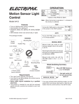
ALL METAL MOTION SENSOR
QUARTZ LIGHT CONTROL
Model HD-9260
© 2000 DESA International 598-1007-02

-2-
598-1007-02
Contents
Introduction .................................................................................................. 3
Package Contents ..................................................................................... 4
Installation ..................................................................................................... 5
Wall Mount ............................................................................................... 5
Eave Mount ............................................................................................... 5
Universal Adaptor .................................................................................... 6
Standard Wiring ....................................................................................... 6
Controlling Non-Motion Sensing Fixtures ............................................. 7
Finish Mounting ....................................................................................... 8
Specifications ............................................................................................ 8
Test and Adjustment .................................................................................... 9
Expected Coverage .................................................................................10
Operation .................................................................................................... 12
Troubleshooting Guide.............................................................................. 13
JourneyMan
®
Lifetime Warranty ...............................................................14

-3-
598-1007-02
Introduction
Enhanced Performance Features
☞ Rugged gripping teeth and finger screw provide full three-dimension adjustment of sensor head.
☞ Eight silicon rubber gaskets seal internal components and controls from severe environmental conditions.
☞ Stainless steel screws to prevent rust and corrosion.
☞ Built in 1.25 Mega Watt surge protection.
☞ A.S.I.C. (Application Specific Integrated Circuit) design allows more reliable performance.
☞ Range Boost option to extend range for those hard to cover areas.
☞ Extremely wide angle coverage (up to 270°).
☞ Easy to control other lights with your JourneyMan
®
fixture (up to 1000 Watts total load).
☞ Expanded lens area receives more infrared light improving detection sensitivity.
☞ Pulse count technology reduces false sensing from wind and rain for professional reliability.
☞ Automatic photocell deactivates unit in daylight to save energy.
☞ Power outage reset. Turns light off automatically if turned on by power interruption or electrical storm.
☞ Selectable light timer to set the time lights stay on after motion has been detected.
☞ Sensitivity control allows adjustment of coverage range.
☞ Manual override to turn lights on/off at your convenience with existing indoor wall switch.
Dear Consumer:
We would like to thank you for purchasing this JourneyMan
®
product. We at Heath
®
/Zenith feel
that you have purchased the most durable motion sensor available today. This JourneyMan
®
product
will give you a lifetime worth of operation. We are so confident with the durability of this product that
we are backing it with a Lifetime Warranty.
Heath
®
/Zenith

-4-
598-1007-02
Package Contents
• Motion Sensor Light Fixture
• Lens shield
• Two 250 watt halogen lamps
• Manual
• Hardware Pack
1 Gasket
1 Hanger
1 Universal adaptor plate
4 Wire nuts
2 #6-32 X 3/4" (19 mm) screws
(for small rectangular boxes)
2 #8-32 X 3/8" (10 mm) screws
(fixture to universal adaptor)
4 #8-32 X 3/4" (19 mm) screws
(for circular or octagon boxes)
2 #10-24 X 1/2" (13 mm) screws
(for water tight boxes)
Additional Items Needed
• Phillips screwdriver
• Ladder
Fits All Junction Box Configurations
Circular
Horizontal rectangular
Vertical rectangular
Octagon

-5-
598-1007-02
Installation
If you want to use the Manual Override feature you will need to install the fixture on a circuit controlled
by a switch. The lamps are packed in boxes, inside the lampheads. Open the lampheads by removing
the screws at the top. Use a clean cloth or the foam packing around the lamps to keep your fingers off
the lamps. Install the lamps in the right side of the sockets first, then the left. Close the lampheads and
continue the installation as shown below.
❒ Loosen the thumbscrews holding the sensor
head and lampheads.
❒ Adjust the various parts so that the fixture
looks similar to this illustration.
❒ Finger tighten the thumbscrews at this time.
Wall Mount Eave Mount
❒ Loosen the thumbscrews holding the sensor
head and lampheads.
❒ Adjust the various parts so that the fixture
looks similar to this illustration.
❒ Finger tighten the thumbscrews at this time.
CAUTION: To Avoid Fire Or Burn Hazards:
• Allow fixture to cool before touching. The bulb and the fixture
operate at high temperatures.
• Keep fixture at least 3" (76 mm) from combustible materials.
Do not aim at objects closer than 3' (1 m).
• Use only type T 250W (max.) tungsten halogen 120 VAC lamps.
CAUTION: BEFORE STARTING THE INSTALLATION, TURN THE POWER OFF AT THE
CIRCUIT BREAKER.

-6-
598-1007-02
CAUTION: If you have not already turned the
power off at the breaker or fuse, do so now.
Make sure the gasket is in place before connect-
ing any wires. You may find it convenient to use
the wire hanger provided to hold the fixture to the
junction box during the wiring process.
Connect the junction box wires to the fixture wires.
Twist together and secure with wire connectors.
CAUTION: If you are not controlling additional
fixtures from your JourneyMan
®
fixture, DO NOT
connect the RED wire.
If you are mounting the JourneyMan
®
fixture to a
small rectangular box, you will need to use the
universal adaptor as shown below. Other boxes
may require the adaptor adjusted differently.
If you are using a standard octagon or round box,
the adaptor is probably not required.
#6-32
screw
Use these holes and the #8-32
X 3/8" (10 mm) screws provided
to secure the fixture.
Horizontal Box
#6-32
screws
Use these holes
and the #8-32 X
3/8" (10 mm)
screws provided
to secure the
fixture.
Vertical Box
#6-32
screw
If the mounting holes in the fixture base still do
not line up with the threaded holes in the univer-
sal adaptor, you can (1) remove the adaptor and
flip it over or (2) remove the other pair of knock
outs in the fixture base.
Standard WiringUniversal Adaptor
Black to
Black
White to
White
Junction
Box
Green ground
wire to junction
box ground wire
RED, not
used in most
applications
Gasket

-7-
598-1007-02
Controlling Non-Motion Sensing Fixtures
❒ When wiring to additional standard fixture
only: Strip the motion sensor's red wire and
connect to the standard fixture's black wire.
Connect all white wires together. Total fixture
ratings must not exceed 1000W (8.3 A).
NOTE: All wiring between fixtures should be run
in accordance with the National Electrical Code
through conduit or another acceptable means.
Contact a qualified electrician if there is any
question as to the suitability of the system.
❒ This fixture is provided with a sensor rated
for 1000W. Since the fixture is only rated 500W,
500W of additional load may be controlled by
this sensor.
❒ When determining what a fixture is rated for,
do not simply look at the rating on the lamp in
the fixture. Look at the marking which speci-
fies the maximum lamp wattage for which the
fixture is suitable.
❒ Once you have selected the fixtures to be con-
nected and determined their maximum ratings,
add these ratings up. For instance, if you have
3 fixtures rated 100W, 150W, and 75W respec-
tively, you have a total load of 325W.
Wiring to a Motion Light & Standard Fixture
Standard
Fixture
RED from JourneyMan
®
to
BLACK from Fixture
BLACK from Switch to
BLACK from JourneyMan
®
WHITE from Line to
WHITE from JourneyMan
®
WHITE from Line to
WHITE from Fixture

-8-
598-1007-02
Finish Mounting
❒ Align the JourneyMan
®
base plate, gasket, and
the junction box holes. Secure with mounting
screws that fit your junction box.
❒ If not installed on a weatherproof box or if the
adaptor plate was used, caulk between the
base plate and mounting surface with sili-
cone weather sealant.
To obtain maximum lamp
life, keep the tubular
lamps horizontal.
Specifications
Range .............................. Up to 100 feet (30.5 m) with
Range Boost On; up to 70
feet (21 m) with Range
Boost Off. (Varies with sur-
rounding temperature).
Sensing Angle................. Up to 270°
Fixture Load ................... 500 watts max., Incandescent
(250W each lamp holder)
Sensor Load Capacity..... 1000 watts (8.3 amps), In-
candescent
Power Requirements....... 120 VAC, 60 Hz
Operating Modes ............ TEST, AUTO and MANUAL
MODE
Time Delay ..................... 1 , 5, 20 minutes
Sensitivity ....................... Adjustable
CAUTION: To Avoid Fire Or Burn Hazards:
• Allow fixture to cool before touching. The bulb and the fixture
operate at high temperatures.
• Keep fixture at least 3" (76 mm) from combustible materials.
Do not aim at objects closer than 3' (1 m).
• Use only type T 250W (max.) tungsten halogen 120 VAC lamps.

-9-
598-1007-02
Test and Adjustment
NOTES: When first turned on or when switching
from Manual to Auto mode wait 1
1
/
2
minutes for the unit to calibrate.
Testing with Range Boost on during day-
light may result in abnormal operation.
❒ Turn on the circuit breaker and light switch.
❒ Open the control access cover (on bottom of unit)
by pulling down on the tab of the rubber cover.
❒ Turn the sensitivity control to the center of its
adjustment, RANGE BOOST to OFF and the
ON-TIME to TEST position.
Sensor Bottom
Don't aim the control at:
• Objects that change temperature rapidly, such
as heating vents and air conditioners, to help
avoid false triggering.
• Where pets or traffic may trigger the control.
• Nearby large, light-colored objects reflect-
ing light may trigger the shut-off feature. Do
not point other lights at the sensor.
MIN. MAX.
SENSITIVITY
Range Boost
OFF
ON
ON TIME
TEST 1 5 20

-10-
598-1007-02
Adjustments Continued . . .
Aim Sensor Down
for Short Coverage
❒ Loosen the wing screws, estimate the direction to aim the sensor and
tighten the wing screws just enough to hold the sensor in place.
❒ Walk through the coverage area noting where you are when the lights
turn on. Loosen the wing screws and readjust the sensor as necessary.
Tighten the wing screws (finger tight) when you are satisfied with the
coverage direction. Keep the sensor at least 1 inch (25 mm) from
lamps and keep the controls on the bottom.
❒ Adjust SENSITIVITY as needed to increase or decrease the range. Too
much sensitivity may increase false triggering.
❒ Set the amount of TIME (1, 5 or 20 minutes) you want the lights to stay
on after motion is detected at night.
❒ If you need to detect objects more than 70 feet (21 m) away, turn Range
Boost on.
❒ Replace the rubber cover to protect controls.
Aim Sensor Out for
Long Coverage
Expected Coverage
The sensor is less sensitive to motion directly
towards it, most sensitive to motion across its field
of view.
Motion
Sensor
Least Sensitive Most Sensitive
100 ft.
(30.5 m)
Boosted
Maximum Range
When mounted 8 feet (2.4 m) from the ground,
you may expect the range shown below. If
mounted much higher the sensor may miss ob-
jects near the ground. If mounted much lower the
sensor range may be reduced.
8 ft.
(2.4 m)
Motion
70 ft.
(21 m)

-11-
598-1007-02
If the wide angle (270°) coverage is too wide for
your application, you may need to install the lens
shield to reduce the coverage angle.
❒ Decide which side of the lens you want to cover.
❒ Curve the shield as shown. Slide the shield
down, under the two metal ribs of the case.
Make sure the shield slides all the way down
so the entire shield will lay directly against
the lens.
❒ Slip the small protrusion behind the vertical
metal rib to hold the top of the shield in place.
Maximum
Coverage Angle
If the sensor is not kept level you may experi-
ence an apparent decrease in range because
objects may pass under the detection zone with-
out being detected.
270°
Approx. area
blocked by the
lens shield (if
used)
Slip behind
vertical rib
Lens shield
Metal
ribs

-12-
598-1007-02
Operation
RANGE BOOST
Turn Range Boost on for addi-
tional coverage only if needed.
Off
On
Range Boost
Put the ON-TIME switch on the
sensor bottom in TEST and the
Range Boost switch to Off.
TEST 1 5 20
ON TIME
TEST
AUTO
ON TIME
TEST 1 5 20
Put the ON-TIME switch in the
1, 5 or 20 minute position.
* resets to Auto Mode at dawn.
Test 5 Sec x x
Auto 1, 5 or 20 min. x
Manual Until Dawn* x
Mode: On-Time: Works: Day Night
MANUAL MODE
... back on.
1 Second OFF
then
...
Manual Mode only works at
night because daylight returns
the sensor to AUTO.
Flip the light switch off for one
second then back on to toggle
between AUTO and MANUAL
MODE.
Manual Mode works with the
ON-TIME switch in the 1, 5,
or 20 minute position.
Move ON-TIME Switch
to 1, 5 or 20 minutes
Flip light switch
off for one second
then back on*
* If you get confused while switching modes,
turn the power off for one minute, then back
on. After the calibration time, the control will
be in the AUTO mode.
MANUAL MODE
AUTO
TEST

-13-
598-1007-02
Troubleshooting Guide
If you have a problem, please follow this guide. You may also want to visit our Web site at: www.desatech.com. For
more help call 1-800-858-8501 8:00 AM to 4:30 PM Central Time weekdays.
Lo sentimos, pero no podemos contestar preguntas en español por teléfono.
SYMPTOM
Lights will
not come
on.
1. Light switch is turned off.
2. Flood light is loose or burned out.
3. Fuse is blown or circuit breaker is
turned off.
4. Daylight turnoff is in effect.
(Re-
check after dark)
.
5. Incorrect circuit wiring, if this is a
new installation.
6. Re-aim the sensor to cover de-
sired area.
Lights
come on in
daylight.
Lights come
on for no
apparent
reason.
1. Control may be installed in a rela-
tively dark location.
2. Control is in Test.
(Set control
switch to an ON-TIME position)
.
1. Control may be sensing small ani-
mals or automobile traffic.
(Re-
aim sensor or use lens shield)
.
2. Sensitivity is set too high.
(Reduce
sensitivity. Turn Range Boost off)
.
POSSIBLE CAUSE
1. Heat or light from the lamps may be
turning the Light Control on and off.
(Aim lamps away from the sensor. Turn
Boost off).
2. Reflected heat from other objects are
triggering the sensor. (
Re-aim sensor.
Turn Boost off).
3. Control is in warming up.
(Flashing is
normal under these conditions. Wait 1
minute for sensor to warm up).
4. Control is in Test.
(Set control switch to
an ON-TIME position).
Lights flash
on and off.
SYMPTOM
Lights stay on
continuously.
POSSIBLE CAUSE
1. A lamp is positioned too close to the
sensor or pointed at objects that causes
the sensor to trigger.
(Aim the lamp
away from the sensor or objects)
.
2. Control is pointed at a heat source like
an air vent, dryer vent, or brightly-painted
heat-reflective surface.
(Re-aim sen-
sor. Turn Boost off).

-14-
598-1007-02
JourneyMan
®
Lifetime Warranty
This is a "Limited Warranty" which gives you specific legal rights. You may also have other
rights which vary from state to state or province to province.
For as long as you (the original purchaser) own this JourneyMan
®
product, any malfunction
caused by factory defective parts or workmanship will be corrected at no charge to you. Light
bulbs are not covered. To obtain a refund or a replacement, return the product to the place of
purchase.
Not Covered - Repair service, adjustment and calibration due to misuse, abuse or negli-
gence, light bulbs and other expendable items are not covered by this warranty.
Unauthorized service or modification of the product or of any furnished component will
void this warranty in its entirety. This warranty does not include reimbursement for incon-
venience, installation, setup time, loss of use, or unauthorized service.
This warranty covers only JourneyMan
®
products and is not extended to other equipment
and components that a customer uses in conjunction with our products.
THIS WARRANTY IS EXPRESSLY IN LIEU OF ALL OTHER WARRANTIES, EXPRESS
OR IMPLIED, INCLUDING ANY WARRANTY, REPRESENTATION OR CONDITION OF
MERCHANT ABILITY OR THAT THE PRODUCTS ARE FIT FOR ANY PARTICULAR PUR-
POSE OR USE, AND SPECIFICALLY IN LIEU OF ALL SPECIAL, INDIRECT, INCIDENTAL,
OR CONSEQUENTIAL DAMAGES.
REPAIR OR REPLACEMENT SHALL BE THE SOLE REMEDY OF THE CUSTOMER
AND THERE SHALL BE NO LIABILITY ON THE PART OF HEATH FOR ANY SPECIAL,
INDIRECT, INCIDENTAL, OR CONSEQUENTIAL DAMAGES, INCLUDING BUT NOT LIM-
ITED TO ANY LOSS OF BUSINESS OR PROFITS, WHETHER OR NOT FORESEEABLE.
Some states or provinces do not allow the exclusion or limitation of incidental or conse-
quential damages, so the above limitation or exclusion may not apply to you. Retain receipt
for warranty claims.

-15-
598-1007-02
CONTROL CON LUZ DE
CUARZO Y DETECTOR DE MOVIMIENTO
TODO DE METAL
Modelo HD-9260
© 2000 DESA International 598-1007-02 S

-29-
598-1007-02
COMMANDE D’ÉCLAIRAGE AU QUARTZ
TOUT MÉTAL À DÉTECTEUR DE
MOUVEMENT
Modèle HD-9260
© 2000 DESA International 598-1007-02 F
/