Page is loading ...

1
Robert H. Peterson Co.
Models
G46-18/20-01(P)
G46-18/20-11(P)
G46-18/20-15(P)
G46-18/20(P)
G46-24-01(P)
G46-24-11(P)
G46-24-15(P)
G46-24(P)
G46-30-01(P)
G46-30-11(P)
G46-30-15(P)
G46-30(P)
RHP
OWNER’S
OWNER’S
MANUAL
MANUAL
No.L-A2-21506
REV 2 0603020800
ROBERT H. PETERSON CO. 14724 East Proctor Ave., City of Industry, CA 91746
Your Peterson Real-Fyre Gas Log Set is to be installed
only in a solid-fuel burning fi replace with a working fl ue
constructed of noncombustible material. Solid fuels
shall not be burned in a fi replace where this gas log
set is installed. The installation, including provisions
for combustion, ventilation air and required minimum
permanent vent opening, must conform with the National
Fuel Gas Code (ANSI Z21.60a-2003 and CSA 2.26a-
2001) and applicable local building codes. In Canada,
the installation must conform with the current CAN/
CGA B149.1, and B149.2 Installation Code.
Z223.1)
and applicable local building codes. A damper clamp
is included to maintain the minimum permanent vent
opening and to prevent full closure of the damper
blade. The chimney damper MUST be fully open
when burning the log set. Your log set is designed
to burn with yellow fl ames; adequate ventilation
is absolutely necessary.
Installation and service must be
performed by an NFI Certifi ed or other
qualifi ed, professional installer, service
agency or the gas supplier.
IMPORTANT: To comply with certifi cation, listings,
and building codes, and for safe operation and
proper performance, ONLY Peterson parts and
accessories MUST be used with this gas log set.
IMPORTANT: READ THESE INSTRUCTIONS
CAREFULLY BEFORE STARTING
INSTALLATION OF YOUR LOG SET
- Do not store or use gasoline or other
fl ammable vapors and liquids in the
vicinity of this or any other appliance.
- WHAT TO DO IF YOU SMELL GAS.
• Open a window.
• Do not try to light any appliance.
• Do not touch any electrical switch; do not
use any phone in your building.
• Immediately call your gas supplier from
neighbor's phone. Follow the gas
supplier's instructions.
• If you cannot reach your gas supplier,
call the fi re department.
WARNING: If the information in this
manual is not followed exactly, a fi re or
explosion may result causing property
damage, personal injury or loss of life.
G46 SERIES BURNER
INSTALLER & CONSUMER :
These Instructions MUST be
retained with this appliance
C.S.A. CERTIFIED
GLOWING EMBERS
GAS FIREPLACE
LOG SET

3
G46 GAS LOG SET
TABLE OF CONTENTS
Cover - Important Safety Warnings 1-2
Table of Contents 3
Burner - Parts Lists:
General Burner and Log Parts List 4
G46 Manual Valve System 5
G46-11 Remote Valve System 5
G46-01 Electronic Valve System 6
G46-15V Remote Valve (Variable fl ame) System 6
Important Information:
General information
Technical Data Table
Minimum Damper Opening Data 7
Installing your gas log set:
Damper clamp Installation 8
Installation of the burner 8-9
Special Instructions for G46-01 Installation 10
Securing the burner 11
Granule and ember placement 11
Log Placement 12-13
Optional Log Placement (Charred series and Campfyre) 14-15
Lighting Instructions:
G46 Manual valve 16-17
G46-11 Remote valve 18-19
G46-01 Electronic valve 20-21
G46-15 Remote Variable fl ame valve 22-23
Operating Information:
Pilot Burner Adjustment 24
Flame pattern adjustment 25
Maintenance 25
Warranty 26
TOPIC
PAGE #

4
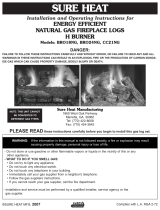
PARTS LIST FOR REAL-FYRE G46 SERIES GLOWING EMBER GAS LOG SETS
Log styles, sizes and parts will vary depending upon
the G46 Series model ordered.
When ordering replacement parts, be sure to
indicate your log set model.
NOTE: Only the logs for the WO-24 Woodland Oak 24" Set
are illustrated and listed below.
Item Description
No.
ON
OFF
PILOT
1. 20" rear log
2. 24" front log
3. 15" top left log
4. 15" top right log
5. 9" top left log
6. 9" top right log
7. Grate
8. Log locators with screws
9. Burner pan assembly
10. G46 safety control system (see Pages 5-6)
11. Piezo ignitor assembly
12. Pilot assembly
13. Sand (natural gas)
or Vermiculite (L.P. gas)
14. Glowing embers
15. Damper clamp
16. Connector kit
G46-01 Electronic Burner
(Top view)
G46-11 Burner
(Top view)
G46 Burner with
Manual Control (Top view)
G46-15 Burner
(Top view)
11
16
15
2
1
5
6
3
4
7
9
10
12
14
13
NOTE: Photos not to scale
Actual parts may differ.
8

5
SAFETY CONTROL SYSTEM FOR G46 MANUAL
SAFETY CONTROL SYSTEM FOR G46-11(P)
G46 Burner showing valve layout
under heat shield.
NOTE: DO NOT REMOVE HEAT SHIELD
23
24
Item No. Description
23. Safety control valve
24. Brass elbow 1/2" fl are x 3/8"MIP
G46 Burner showing valve layout
under heat shield (rear view).
NOTE: DO NOT REMOVE HEAT SHIELD
17
18
19
20
22
PILOT ASSEMBLY
(Rear view)
Item Description
No.
17. Safety control valve
18. Pressure regulator (natural gas)
Pressure regulator (L.P. gas)
19. Handle assembly
20. Pilot assembly
21. Ceramic electrode
22. Adapter elbow
LOCATION OF
ORIFICE
PILOT
ASSEMBLY
(ITEM 20)
CERAMIC
ELECTRODE
(ITEM 21)

6
SAFETY CONTROL SYSTEM FOR G46-01(P)
G46 Burner showing Remote Control layout under heat shield.
NOTE: DO NOT REMOVE HEAT SHIELD
SAFETY CONTROL SYSTEM FOR G46-15(P)
G46 Burner showing 15 valve
under heat shield.
NOTE: DO NOT REMOVE HEAT SHIELD
FLAME HEIGHT
CONTROL KNOB
SUPPLIED VR-1 REMOTE WITH RECEIVER,
HEATSHIELD, BATTERIES & WIRING
ON/OFF IGN/PILOT
KNOB
CONNECTION TERMINALS FOR
VR-1 WIRING TO RECIEVER
26
25
25. Safety control valve
26. Pilot assembly
Item Description
No.
27
28
27. Safety control valve
28. Pilot assembly
Item Description
No.

7
G46 SERIES IMPORTANT INFORMATION
Do not use this log set if any part has been under
water. Immediately call a qualifi ed professional
service technician to inspect the appliance and to
replace any part of the control system and any gas
control which has been under water.
The appliance and its individual shutoff valve must
be disconnected from the gas supply piping system
when testing the system at test pressures in excess
of ½ psig. This is accomplished by closing the gas
supply line valve, which is required by NFPA54,
section 5.54.
Keep the area of the gas log set clear and free from
combustible materials, gasoline and other fl am-
mable vapors and liquids.
The minimum inlet gas supply pressure for the
purpose of input adjustment is 5" for natural
gas and 11" for propane gas. The maximum inlet
gas supply pressure for this burner is 14" for
natural and propane gas.
A fi replace screen must be in place when the log
set is burning. Provisions for adequate combustion
air must be maintained. Combustion air is adequate
when all fl ames curl into the fi replace and away from
the screen.
When glass fi replace doors are used, operate the
gas log set with the doors open.
The minimum size fi replace in which the log set is to be
installed is listed in the "Technical Data Table" below.
The minimum chimney height from the hearth to the
top of the chimney is 15'
.
THIS GAS LOG SET CONFORMS TO THE
ANSI Z21.60a -2003 STANDARD.
18"&20" 24" 30" 18"&20" 24" 30"
15' 15 SQ" 21 SQ" 29 SQ" 23 SQ" 31 SQ" 40 SQ"
20' 14 SQ" 18 SQ" 24 SQ" 21 SQ" 28 SQ" 36 SQ"
25' 12 SQ" 16 SQ" 21 SQ" 20 SQ" 27 SQ" 34 SQ"
30' 10 SQ" 15 SQ" 19 SQ" 19 SQ" 26 SQ" 33 SQ"
*Note: A damper stop clamp is provided as a means to prevent full
closure of the damper blade. Fully open the damper when burning
the log set (see page 8 for details on the damper clamp).
Your log set is designed to burn with yellow fl ames;
Adequate ventilation is absolutely necessary.
Chimney
Height
Minimum Free Opening Area of Chimney Damper for Venting
For Factory Built Fireplaces
Log Set Sizes
For Masonry Built Fireplaces
Log Set Sizes
*
IMPORTANT: To comply with certifi cation, listings and building code acceptances and for
safe operation and proper performance ONLY Real-Fyre parts and accessories may be
used with this gas log set. Real-Fyre valves, controls, parts and accessories have been
designed, tested and certifi ed for use with Real-Fyre Gas Log Sets. Use of other controls,
parts and accessories which are not designed for use with Real-Fyre Gas Log Sets is
prohibited and will void all warranties, certifi cations, listings and building code approvals,
and may cause property damage, personal injury or loss of life.
Log Set Front
Depth Height Nat. Propane
18" 24" 13" 16" 40,000 40,000
20" 26" 13" 16" 40,000 40,000
24" 30" 13" 16" 55,000 55,000
30" 36" 13" 16" 65,000 65,000
BTU Rating
Real-Fyre G46 Series Technical Data Table
Minimum Fire Box Dimensions
Opening
Size

8
DAMPER CLAMP INSTRUCTIONS
The damper clamp with hex bolt (Figure 1) is provided as a means to prevent full closure of the
damper blade. The clamp is easily attached to most damper blades with pliers or wrench, and must
be permanently installed. The clamp is designed to prevent accidental closure of the damper when
installed as illustrated (Figures 2 A&B). Should the clamp not fi t, or provide the permanent vent opening
listed on the table found on page 7, have a permanent stop installed, remove the damper blade or
have the damper cut to provide the minimum permanent opening required.
DAMPER STOP CLAMP INSTRUCTIONS
Your Peterson Real-Fyre gas log set must be installed by an NFI Certifi ed or other qualifi ed, professional
installer. Instructions must be followed carefully to ensure proper performance and an aesthetically
pleasing product. Check to be sure your log set is designed and labeled for the type of gas (natural
or propane gas) supplied to your fi replace. Never use a log set designed for natural gas with propane
gas or a log set designed for propane gas with natural gas. Real-Fyre gas logs must be installed only
in a wood-burning fi replace with the minimum venting requirements met (see page 7). Fireplace fl oor
must be level, clean and smooth. Check parts list to be sure all parts are included. Gas supply pipe
inside diameter (I.D.) must be 1/2" or larger. 3/4" I.D. may be necessary if gas line is longer than 20'.
You should adjust and align the pilot prior to installing by using the fl ex connector kit (Item 16). Attach
your connector kit to the gas supply and the burner outside the fi replace. This will allow you to move
the burner at an angle in order to access the pilot adjustment screw on the valve (see page 24 for pilot
adjustment).
INSTALLING YOUR REAL-FYRE GAS LOG SET
CONNECTOR KIT
GAS
SUPPLY
LARGE ADAPTER
BURNER
VALVE
GAS INLET
ELBOW
Postion of Burner Gas Inlet Valve on
G46-11 Model
Figure 3
Figure 2A Figure 2B
Damper Clamp
Figure 1
SET SCREW
Open Closed

9
1. The burner gas inlet is located in front of the gas
valve (Figure 3). Use tefl on tape or pipe compound
on all pipe thread male connections, except where
brass to brass.
FOR THE G46 AUTOMATIC MILLIVOLT VALVE Attach
the connector kit 3/8" adaptor to the brass elbow (Item
No. 24) on the valve. The log set user should make
themselves familiar with the valve control layout before
installing the burner into the fi replace.
2. Next clamp the log locators onto the grate fi ngers
(one in from either end). The log locators will fi t on either
side of the grate fi nger (see Figure 4a and b). Align the
locator screw so that it projects down into the locator
holes on the burner. Attach nuts to screws and fi nger
tighten only. Place the bottom log on the grate (see Figure
4c) and align the log against the locator. Fully tighten
the screws and then remove the logs and grate until
completing gas connection and granule placement.
3. Position the burner in the center rear of the fi replace.
Connect the connector kit tubing (Item 16) to your gas
supply. Be sure that the burner assembly and the valve
remain in alignment. If the valve shifts position during
installation, the burner assembly may not sit fl at in the
fi replace, causing improper gas fl ow. It may also cause
interference with the control knob operation.
• Make sure that the safety control system is in the
"OFF" position.
• Turn on the gas to the fi replace and check for leaks
at all connections by using a soapy water solution.
Never use an open fl ame to check for leaks.
• Light the pilot (pages 16-23) and check for proper
adjustment. If the pilot needs to be adjusted, follow the
instructions on page 24. Turn the pilot off.
• Position the grate on the burner (Figure 4c). Push the
burner-grate assembly as far as possible to the rear of
the fi replace, then remove the grate.
NOTE: REFER TO PARTS LIST (PAGE 4) WHEN FOLLOWING THESE INSTRUCTIONS.
INSTALLATION OF LOG SET IN YOUR FIREPLACE
(be sure the gas to the fi replace is off)
IMPORTANT:
Log locators may be installed in either confi guration (A or B),
depending on burner size. Adjust as necessary to ensure screws
fi t in locator holes in burner. This secures the burner and grate
from movement, and keeps the logs in place for optimum log
set operation.
INSTALLING YOUR REAL-FYRE GAS LOG SET (Continued)
NOTE: IF YOUR LOG SET IS A G46-01(P) MODEL CONTINUE
FOLLOWING THE INSTRUCTIONS ON PAGE 10.
FOR ALL OTHER MODELS PROCEED TO PAGE 11.
Figure 4B
B
A
Figure 4A
HEAT
CHAMBER
LOG
LOCATORS
FRONT
BOTTOM
LOG
LOG
LOCATOR
SCREW
GRATE
BURNER
REAR
BOTTOM
LOG
Figure 4C
Log locator
Grate
Burner

10
CONNECTING THE IGNITION PACK TO THE G46-01(P) VALVE
The G46-01-xx(P) valve comes complete with the wiring harness connected to the pine cone switch. You may
wish to ensure it is correctly connected before fi nally connecting the 3 wires to the valve as below.
PINE CONE PLACEMENT
The designer pine cone incorporating
the control switch is aesthetically
designed and is an integral part of the
operation of your set. The pine cone
can be placed as close to the valve
as you desire, but never closer than
4" from the fl ame.
CAUTION: THE PINE CONE MAY
BE HOT DURING AND DIRECTLY
AFTER OPERATION OF YOUR
GAS LOG SET.
G46
Electronic
Valve
TO PILOT ASSEMBLY
PROBES
I
S
VALVE MAGNET
WIRE (BLACK)
(DO NOT REMOVE)
IGNITOR PACK
PINE CONE
SWITCH
WIRE HARNESS
(BLACK) TO
BATTERY
HOLDER
(BROWN)
2 WIRES
TO SWITCH
GREEN (TH)
BLACK (TP)
ORANGE (THTP)
I
S
(RED) TO
BATTERY
HOLDER
(Drawings not to scale.)
Wiring Diagram for 01 remote switch
INSTALLING YOUR REAL-FYRE GAS LOG SET (Continued)
SPECIAL INSTRUCTIONS FOR G46-01-xx(P) MODELS
Installing pine cone with switch for 01M models
TO CHECK THE WIRING ASSEMBLY:
A. Check that the wiring harness is fi tted tightly into the
connector on the green ignitor pack in the rear of the
pine cone (Figure 5A).
B. Check that the female connectors on the two black wires
from the pilot assembly (wires marked "I" and "S") are
inserted fully into the male connectors on the ignitor pack
(Figure 5B).
C. Check the connection of the red and black wires of the
wire harness to the respective counterpart wires from the
battery holder (red-red and black-black). The two brown
wires should be connected to the switch.
Note: the 2 spare brown wires with coated male connectors
are used to connect an optional remote system.
D. Finally connect the wires to the valve in the following
order (see Figure 6):
Orange wire marked THTP - to THTP connector on valve
Black wire marked TP - to TP connector on valve
Green wire marked TH - to TH connector on valve
CHECK CONNECTIONS
I WIRE
S WIRE
WIRE HARNESS
CONNECTOR
IGNITOR PACK
B
A
Figure 5
STEP 5 (A-B)
INSTALLING OR REPLACING BATTERIES FOR IGNITION
MODULE PACK
Two 1.5-volt (D-cell) alkaline batteries are supplied with your
log set. To install or replace batteries, remove the green ignition
module pack, held in place with a velcro strip, from rear of the pine
cone receiver (Figure 7). Remove battery holder and old batteries
from the pine cone. Replace (or install) batteries into the battery
holder, making sure they are installed according to the diagram in
battery holder. Replace holder, pressing it fi rmly against the velcro
strip. Replace ignition pack and press fi rmly into place. The ignition
system is now ready to operate.
NOTE: For your system to work properly, it is suggested that you
replace batteries annually with fresh batteries. Always replace all
the batteries at the same time.
Battery holder
with batteries
Pine cone
cover
with switch
Ignition Module Pack
Velcro
strips
GREEN
WIRE
MARKED
TH
BLACK
WIRE
MARKED
TP
ORANGE
WIRE
MARKED
THTP
D
Figure 6
STEP 5(D)
Figure 7

11
SECURING THE BURNER
Your gas log set has 2 securing holes at the front of the burner pan heat shield (see parts list and Figure
8 for location). Mark the center point of each hole and drill a 3/16" pilot hole (one for each side) into the
fi replace fl oor. Secure with 1/4" anchor bolts.
GRANULE PLACEMENT
Fill the burner pan completely with granules (Item 13). Slope the granules at the same angle as burner pan.
Do not allow granules to spill over front lip, sides or back of the burner.
DO NOT PLACE GRANULES ON
IGNITOR SHIELD OR KNOB SHIELD.
EMBER PLACEMENT
After breaking up any clumps, sprinkle embers (Item 14), lightly and evenly over entire surface of the granules.
You may sprinkle the embers (not the granules) over knob and ignitor shields, making sure to keep embers
clear of pilot assembly.
Embers around the pilot will block air fl ow, causing the pilot to overheat and shutdown the system.
To check operation, light pilot and burner (pages 16-23).
IMPORTANT
For all valves, the air MUST be purged from the gas line before the pilot will light and burn properly. The time needed
to purge will depend on the length of the gas line to the unit and the amount of time since the unit or gas line was
last used. It may take several minutes before all the air is purged and the pilot will light and burn properly. Follow the
"Lighting Instructions" (pages 16-23) in this manual.
INSTALLING YOUR REAL-FYRE GAS LOG SET (Continued)
Figure 8
PERFORATED
AREA
IGNITOR
SHIELD
PILOT
ASSEMBLY
EMBERS
LOG LOCATOR
BOLTS
BURNER
SECURING
HOLE
LOCATOR
HOLE
EMBERS
ONLY
24" unit shown.

12
Note: For Charred Series see Page 14
For Western Campfyre Series see Page 15.
Proper log placement is important to insure proper performance of your Real-Fyre gas log set. Be sure to follow
the log placement instructions carefully. 3 optional log placement patterns, an exclusive feature of Real-Fyre
gas logs, are explained below.
REAL-FYRE GAS LOG SETS 18"-30".
24" Woodland Oak (WO) log set shown.
For all Options - Step 1. Place the rear bottom log (Log #1) on the
back of the grate (Figure 9), and slide it forward against the log locators.
Place the front log (Log # 2) on the front of the grate and slide it back
against the log locators. The log locators ensure that adequate space
between the logs is maintained for a cleaner burn.
Option 1 - Step 2. Place the the middle log (Log #4) to rest on the front and rear bottom logs as shown
in Figure 10A. Place Log #3 so it rest on Log #4 and the front log, as shown in fi gure
10A. Ensure they are placed across the space between the logs.
Option 1 - Step 3. Place the top logs (Logs #5 & 6) as shown in Figure 10B, with Log # 5 resting on Log
#3 and the front log, and Log #6 resting on the rear log and Log #4.
Option 2 - Step 2. Place the middle logs parallel as shown in Figure 10A. Log #3 is placed with one end
on the front log, the other end resting on Log #4.
Option 2 - Step 3. Place Log #5 resting on the front log and the left middle log, and Log #6 resting on the
rear log and the right middle log as in Figure 10C.
Option 3 - Step 2. Place the middle logs (Logs #3 & 4) so they are parallel, resting on the front and rear
logs across the space as shown in Figure 10D.
Option 3 - Step 3. Place top logs #5 & 6 so they are parallel and rest across Logs #3 & 4, as in Figure
10D.
INSTALLING YOUR REAL-FYRE GAS LOG SET (Continued)
Figure 10C
Option 2
Steps 2 & 3.
4
3
6
5
CAUTION: BURN HAZARD.
LOGS WILL REMAIN HOT FOR SOME TIME AFTER USE.
YOU MUST MAINTAIN THE LOG LAYOUT AS SHOWN TO ENSURE PROPER
OPERATION OF YOUR LOG SET.
IF YOU NEED TO REPOSITION ANY LOG TO MAINTAIN THE PROPER LAYOUT,
USE HEAT RESISTANT GLOVES OR ALLOW LOGS ADEQUATE TIME TO COOL BEFORE HANDLING.
Figure 9
2
1
Figure 10D
Option 3
Steps 2 & 3.
3
4
6
5
4
6
5
3
Option 1
Step 2.
Figure 10A
Option 1
Step 3.
Figure 10B

13
INSTALLING YOUR REAL-FYRE GAS LOG SET (Continued)
The illustrations below (Figures 12A-C and 12D-F for Split Oak) show the three basic log placement
patterns available for G46 Real-Fyre C.S.A. Certifi ed gas log sets. The mirror image of each of the
illustrations is also approved. These log placement patterns are the acceptable patterns for all other sets.
REAL-FYRE GAS LOG SETS OPTIONAL
BONUS LOG PLACEMENT
Your optional bonus log (included with Golden Oak Designer
Plus and Split Oak Designer Plus Log Sets) should be
placed directly above the front or rear bottom logs (Logs
#1 & #2), so it does not extend into the space between the
front and rear logs, as shown in Figure 11.
Figure 12E
Figure 12F
Log #7
Figure 11
Figure 12A
Figure 12B
Figure 12C
Figure 12D
OPTIONAL LOG PLACEMENT PATTERNS SUMMARY

14
If you have purchased this style of log set, follow the instructions below.
NOTE: The logs for the CHD Charred Oak Set are illustrated.
Log styles and sizes will vary depending upon the Charred Series log set ordered.
NOTE: INSTRUCTIONS ON THE FYREBED MAY NOT BE APPLICABLE
The COALS FYREBED (see Figure 13) supplied with your Charred log set, fi ts onto the back of the burner
pan. Place it centrally on the back so the outer front tabs hang over the pan (see Figure 14). Set it so it is
over the pilot assembly, but high enough that it does not interfere with the operation of the pilot (see Figure
13). Cover the surface of the COALS FYREBED with the GLOWING EMBERS, supplied with your Charred
Series log set, making sure to keep the GLOWING EMBERS clear of the pilot assembly. For best glowing
performance, they should be applied evenly and pulled slightly apart so the fi bers are somewhat loose. (It
is not necessary to pile the entire bag of the GLOWING EMBERS). Center fl ame must be clearly visible, or
excessive sooting could occur.
Figure 15
Figure 16
Figure 17
Figure 18
Figure 13 Figure 14
INSTALLING YOUR REAL-FYRE GAS LOG SET (Continued)
CHARRED SERIES LOG PLACEMENT - 24" Charred Oak (CHD) set shown
Step 1. Place the long bottom rear log (Log #1) on the back of the grate with the fl at hollow side facing the
rear of the fi replace. Push the log up against the log locators.
Step 2. Place the two sections of the front log (Log #2L & 2R) on the front of the grate and up against the
log locators. The charred sections should be facing each other, approximately one inch apart at the
top.
Step 3. Place the two top knot hole logs (Logs #3 & #4) so that one end rests on each front log section and
the other end rests on the rear log, as shown in Figure 16. The charred sections should be over the
opening between the front and rear logs.
Step 4. Place the top logs (Logs #5 & 6) as shown in Figure 17, with Log # 5 resting on left hand knot hole
log #3 and the left front log (Log #2L), and Log #6 resting across both knot hole logs to the rear.
Step 5. Place the additional top log (Log #7) so it rests near on the right hand knot hole log (Log # 4) and
on the right front bottom log section (Log # 2R ) as shown in Figure 18.
1
2L
2R
3
4
5
6
7

15
INSTALLING YOUR REAL-FYRE GAS LOG SET (Continued)
WESTERN CAMPFYRE STYLE LOGS LAYOUT SUMMARY
If you have purchased this style of log set, follow the instructions below.
NOTE: LOG PLACEMENT is very important for the proper operation and performance of the
Real-Fyre gas log set. Please follow these instructions carefully. Refer to the photo
(Figure 19) for log numbering and the overall look of the completed layout.
Step 1. Install the coals fyrebed provided with your G46 as shown on page 14.
Step 2. Place the bottom rear log (#1 in the photo) on the back of the grate so that the bark faces to the front.
The two fl at indentations and “V” notch will be face up.
Step 3. Place the left and right logs (#2 & #3) so they rest on the fl at indentations on the rear Log #1 and on
the ends of the grate front bar leg. You may need to adjust slightly to secure in position.
Step 4. Place top log #4 resting with the pointed end fi tting in the “V” notch on the rear log #1. The notch on
the other end of Log #4 rests against the second right side outer grate fi nger (check photo).
Step 5. Place top log #5 with the “Y” end resting securely on the second left side outer grate fi nger, the op-
posite end resting on Log #4 (check photo).
Step 6. Place top log #6 resting in the cutout on right log #3 with its opposite resting on Log #4 (check photo).
Step 7. Place top log #7 (the shortest log) on the fi replace bottom, resting against the front middle grate fi nger
(check photo)
Step 8. Place top log #8 so it rests on Log #4 and on Log #3 (check photo).
Step 9. Place top log #9 (the round log) so it rests against the right front leg and between the two right side
outer grate fi ngers (check photo).
WESTERN CAMPFYRE 24
8
7
1
2
3
4
5
6
9
1. MWCFL-18BR REAR LOG
2. MWCFL-18L LEFT LOG
3. MWCFL-18R RIGHT LOG
4. MWCFL-13T TOP LOG
5. MWCFL-13TY TOP LOG
6. MWCFL-10TY TOP LOG
7. MWCFL-8T1 TOP LOG
8. MWCFL-11T TOP LOG
9. MWCFL-5T TOP LOG
SCREEN 200394
ITEMS
Figure 19

16
1. Use "OFF" only
when complete shutdown
is necessary.
1. STOP Read the safety information on this page.
2. Turn "OFF" any electrical appliance (such as the Peterson warm air circulator) if used with the log set.
3. Push in the gas control handle slightly and turn clockwise
to "OFF" (Figure 20).
NOTE: The handle cannot be turned from "PILOT" to "OFF" unless the handle is pushed in slightly. Do not
force.
Wait fi ve minutes to clear out any gas. If you then smell gas, STOP! Notify your gas supplier or the fi re department
immediately. If you don’t smell gas, go on to step 4.
4. Turn the gas control handle counterclockwise
to "PILOT" (Figure 20). Push the control handle all the way
in and hold it. Press the igniter button one or more times to light the pilot. Continue to hold the control handle
for approximately one minute after the pilot is lit. When you release the handle, it will pop out and the pilot
should remain lit.
• If the handle does not pop out when released, stop and immediately call your service technician or gas
supplier.
• If the pilot will not light, repeat steps 3 - 4 and light the pilot manually.
• If the pilot will not stay lit after several tries, turn the gas control handle to "OFF" and call your service technician
or gas supplier.
5. If an electrical appliance is used with the log set, turn on or reconnect that appliance.
6. Turn the gas control handle counterclockwise
to "ON" (Figure 20) to ignite the burner.
NOTE: Periodically check the pilot fl ame (Figure 26, page 24) for proper fl ame pattern.
MAKE SURE THE THERMOCOUPLE AND PILOT ASSEMBLY ARE IN CORRECT ALIGNMENT WITH EACH
OTHER. (SEE FIGURE 26, PAGE 24).
LIGHTING INSTRUCTIONS FOR G46 MANUAL GAS LOG SETS
TO TURN OFF THE MANUAL GAS LOG SET
1. From the "ON" position, turn the control knob clockwise to the "PILOT" position. The log set will extinguish
and the pilot will remain lit.
2. If complete shutdown is desired, from the "PILOT" position, push in the control knob slightly and turn clockwise
to the "OFF" position. Do not force the knob.
FOR YOUR SAFETY, READ BEFORE LIGHTING
The Real-Fyre G46 Series gas log set has a pilot which can be lit by hand using the piezo ignitor. When lighting
the pilot, follow these instructions exactly.
BEFORE LIGHTING, smell all around the gas log set area for gas. Be sure to smell next to the fl oor as some gas is
heavier than air and will settle on the fl oor. IF YOU SMELL GAS, FOLLOW THE INSTRUCTIONS ON PAGE 1.
Use only your hand to push in or turn the gas control knob. Never use tools. If the knob will not push in or turn by
hand, don't try to repair it. Call a qualifi ed, professional service technician. Force or attempted repair may result
in fi re or explosion.
* We recommend that before you install your log set you familiarize yourself with the control valve layout. This will help
you to be confi dent operating the log set when fully installed (see Figures on page 16-23 for typical control positions).
WARNING: If you do not follow these instructions exactly, a fi re or explosion may result causing
property damage, personal injury or loss of life.
Figure 20
1. LIGHTING - turn knob to "OFF"
and wait 5 minutes before lighting.
2. Turn Dial to "PILOT"
position. With match
ready press knob in and
hold for 60 seconds while
lighting pilot.
3. Turn knob to "ON"
to light burner.
PILO T
ON
OFF
OFF
ON
PILOT
OFF
ON
PILOT
OFF
ON
PILOT

18
1. STOP! Read the safety information above.
2. Turn "OFF" any electrical appliance (such as the Peterson warm air circulator or remote control system)
if used with the log set.
3. Place the "switch" or "remote" in "OFF" position.
4. Push in the control knob and turn clockwise
to the "OFF" position.
5. Wait fi ve (5) minutes to clear out any gas. If you then smell gas, STOP! Follow the instructions on Page 1.
6. Find the pilot by following the metal tube from the gas control. Pilot is located at the right rear of the burner
pan.
7. Turn the gas control knob counterclockwise
to "PILOT" (Figure 21). Push the control knob all the way
in and hold it. Press the igniter button several times to light the pilot. Continue to hold the control knob
for approximately one minute after the pilot is lit. When you release the knob, it will pop out and the pilot
should remain lit.
• If the knob does not pop out when released, STOP! Immediately call your service technician or gas sup-
plier.
• If the pilot will not light, repeat steps 4 - 7 and light the pilot manually.
• If the pilot will not stay lit after several tries, turn the gas control knob to "OFF" and call your service
technician or gas supplier.
8. Turn gas control knob counterclockwise
to "ON".
9. If an electrical appliance is used with the log set, turn on or reconnect that appliance.
10. To operate, fl ip the "toggle switch" to "ON" or put the remote handset in the "ON" position.The burner will
ignite.
NOTE: Periodically check the pilot fl ame for proper fl ame pattern (see Figure 28).
MAKE SURE THE THERMOPILE AND PILOT ASSEMBLY ARE IN CORRECT ALIGNMENT WITH EACH
OTHER (SEE FIGURE 28, PAGE 24).
FOR YOUR SAFETY, READ BEFORE LIGHTING
The Real-Fyre G46 Series gas log set has a pilot which can be lit by hand using the piezo ignitor. When lighting
the pilot, follow these instructions exactly.
BEFORE LIGHTING, smell all around the gas log set area for gas. Be sure to smell next to the fl oor as some
gas is heavier than air and will settle on the fl oor. IF YOU SMELL GAS, FOLLOW THE INSTRUCTIONS ON
PAGE 1.
Use only your hand to push in or turn the gas control knob. Never use tools. If the knob will not push in or turn
by hand, don't try to repair it. Call a qualifi ed, professional service technician. Force or attempted repair may
result in fi re or explosion.
* We recommend that before you install your log set you familiarize yourself with the control valve layout. This will help
you to be confi dent operating the log set when fully installed (see Figures on pages 16-23 for typical control positions).
WARNING: If you do not follow these instructions exactly, a fi re or explosion may result causing
property damage, personal injury or loss of life.
LIGHTING INSTRUCTIONS FOR G46-11 REMOTE GAS LOG SET
1. Place the remote or switch in the "OFF" position. The pilot will remain lit.
2. If complete shutdown is desired, remove the radiant heat shield. Push in the control knob and turn clock-
wise
to the "OFF" position. Replace the radiant heat shield.
1. LIGHTING - turn
knob to "OFF"
and wait 5 minutes
before lighting.
TOGGLE
SWITCH
CONTROL
KNOB
PILOT ADJUSTMENT
UNDER CONTROL
KNOB
HEAT SHIELD
OFF PILOT ON
2. Turn dial to ''PILOT"
position. With
match ready press
knob in and hold for 60
seconds while lighting
pilot.
3. Turn knob to "ON"
to light burner.
1. Use "OFF"
only when complete
shutdown is neces-
sary.
ON
OFF
PILOT
ON
OFF
PILOT
ON
OFF
PILOT
ON
OFF
PILOT
Figure 21
TO TURN OFF THE G46-11 REMOTE GAS LOG SET

20
FOR YOUR SAFETY, READ BEFORE LIGHTING
The Real-Fyre G46 Series gas log set has a pilot which can be lit by hand using the piezo ignitor. When lighting
the pilot, follow these instructions exactly.
BEFORE LIGHTING, smell all around the gas log set area for gas. Be sure to smell next to the fl oor as some gas
is heavier than air and will settle on the fl oor. IF YOU SMELL GAS, FOLLOW THE INSTRUCTIONS ON PAGE 1.
Use only your hand to push in or turn the gas control knob. Never use tools. If the knob will not push in or turn by
hand, don't try to repair it. Call a qualifi ed, professional service technician. Force or attempted repair may result in
fi re or explosion.
* We recommend that before you install your log set you familiarize yourself with the control valve layout. This will help
you to be confi dent operating the log set when fully installed (see Figures on page 16-23 for typical control positions).
WARNING: If you do not follow these instructions exactly, a fi re or explosion may result causing
property damage, personal injury or loss of life.
TO LIGHT THE PILOT AND MAIN BURNER.
1. STOP! Read the safety information above.
2. Turn "OFF" any electrical appliance (such as the Peterson warm air circulator system) if used with the log
set.
3. Place the "switch" (marked " I" = "IGNITE"; "O" = "OFF" , Figure 22) in "OFF" position.
4. Wait fi ve (5) minutes to clear out any gas. If you then smell gas, STOP! Follow the instructions on Page 1.
5. Press the switch on top of the pine cone to the "I" position (see Figure 23). A rapid series of sparks at the pilot
(cobra) head. These sparks cease when the pilot fl ame is lit and stable. When the pilot becomes stable the
electronic valve will open and light the main burner.
CAUTION: IF THE GAS SET DOES NOT IGNITE WITHIN 20 SECONDS, STOP, WAIT 5 MINUTES THEN
REPEAT "TO LIGHT THE PILOT AND MAIN BURNER".
LIGHTING INSTRUCTIONS FOR G46-01 GAS LOG SET
THIS UNIT (G46-01) HAS A NON-STANDING PILOT.
1. Press the switch on top of the pine cone to the "O" position ("O" = "OFF", Figure 24). The gas fl ow will cease
and all fl ames (main burner and pilot) will go out.
PINE CONE SWITCH
Figure 22
Figure 23
Figure 24
PINE CONE SWITCH
IN "ON" POSITION
PINE CONE SWITCH
IN "OFF" POSITION
TO TURN OFF THE G46-01 REMOTE GAS LOG SET

22
1. Using remote handset, turn main burner off by pressing "DOWN" button. Pilot will remain lit.
2. If complete shutdown is desired, WHEN THE LOG SET IS COOL, push in the ignitor knob and turn clockwise
to the "OFF" position. Replace the radiant heat shield.
FOR YOUR SAFETY, READ BEFORE LIGHTING
The Real-Fyre G46 Series gas log set has a pilot which can be lit by hand using the piezo ignitor. When lighting
the pilot, follow these instructions exactly.
BEFORE LIGHTING, smell all around the gas log set area for gas. Be sure to smell next to the fl oor as some
gas is heavier than air and will settle on the fl oor. IF YOU SMELL GAS, FOLLOW THE INSTRUCTIONS ON
PAGE 1.
Use only your hand to push in or turn the gas control knob. Never use tools. If the knob will not push in or turn
by hand, don't try to repair it. Call a qualifi ed, professional service technician. Force or attempted repair may
result in fi re or explosion.
* We recommend that before you install your log set you familiarize yourself with the control valve layout. This will help
you to be confi dent operating the log set when fully installed (see Figures on page 16-23 for typical control positions).
WARNING: If you do not follow these instructions exactly, a fi re or explosion may result causing
property damage, personal injury or loss of life.
LIGHTING INSTRUCTIONS FOR G46-15 GAS LOG SET
1. STOP Read the safety information above.
2. Turn "OFF" any electrical appliance (such as the Peterson warm air circulator or any remote control system) if
used with the log set.
3. Push in ignitor control knob, turn clockwise
to "OFF" position (Figure 25). Turn variable fl ame height
control clockwise
to "OFF" position.
4. Wait fi ve (5) minutes to clear out any gas. If you then smell gas, STOP! Follow the safety information above. If
you don't smell gas, go to the next step.
5. Locate the pilot. Follow the metal tube from the gas control. Pilot is located at the right rear of burner pan.
6. To light pilot, turn ignitor knob from "OFF" position clockwise towards "IGN" until reaching stop. Press ignitor
knob in and hold for 5 seconds (only pilot gas will fl ow).
7. Continue holding knob in, turn the ignitor control knob to "PILOT" to activate the piezo ignitor (you should hear
a click, pilot should light). Continue to hold ignitor knob in for 30 seconds after pilot is lit. Release ignitor knob
and it will pop back up. The pilot should remain lit. If it goes out, repeat steps 5 through 8.
• If the knob does not pop up when released, stop and immediately call your service technician or gas supplier.
• If the pilot will not stay lit after several tries, turn the gas control knob to "OFF" and call your service technician
or gas supplier.
8. Turn ignitor knob counterclockwise
to "ON".
9. With the pilot lit, turn the fl ame height control towards "ON" (counterclockwise
) to desired fl ame height
and heat output. NOTE: When the unit has been burning for some time, use your remote control to adjust the
fl ame height and to turn the unit off.
10. If an electrical appliance is used with the log set, turn on or reconnect that appliance.
TO TURN OFF THE GAS LOG SET
TO TURN OFF THE GAS LOG SET
Figure 25
Ignitor Knob
Flame Height
Control Knob
2. Turn dial to "IGN",
push in and turn to "PILOT"
position. Press knob in and
hold for 60 seconds while
lighting pilot.
OFF PILOT ON
3. Turn knob to
"ON". To light burner
turn variable fl ame
height knob towards
"ON"
1. Use "OFF"
when complete shut-
down is desired.
4. When log set is
hot, press "DOWN"
on handset to turn off
main burner. Pilot will
remain lit.
NOTE: Press "UP" or
"DOWN" on handset to
adjust fl ame height as
desired.
1. LIGHTING - turn all knobs
to "OFF" and wait 5
minutes before lighting.

24
The pilot burner is preset at the factory and normally
should not require adjustment. However, if adjustment
is necessary, the following steps should be taken:
With the pilot burner lit and the control knob in the pilot
position, use a long narrow screwdriver to turn the
pilot adjustment screw (located on front of valve). Turn
the adjustment screw slowly clockwise to reduce the
fl ame, or counterclockwise to increase the fl ame. The
adjustment screw can be turned so that the pilot fl ame
is completely extinguished. The pilot fl ame should be a
quiet soft blue fl ame with yellow tipping which encircles
the thermocouple tip.
Turn the control knob to the "ON" position to assure
proper ignition of the log set.
PILOT BURNER ADJUSTMENT (G46 MANUAL)
Example of proper pilot burner fl ame
and proper pilot/thermocouple alignment
PILOT
ADJUSTMENT
Figure 26
Thermocouple
Thermopile
Figure 28
Example of proper pilot burner fl ame and
proper pilot / thermopile alignment
PILOT ADJUSTMENT SCREW
ON
OFF
PILOT
Figure 27
Position of Pilot Adjustment Screw
PILOT BURNER ADJUSTMENT
The pilot burner is preset at the factory and should
normally not require any adjustment. However, should
adjustment be necessary, the following steps should
be taken:
1. Pull the burner forward so that you can access the
pilot burner adjustment screw.
2. Light the pilot burner (see pages 16-23 for "Lighting
Instructions").
3. With the control knob in the "PILOT" position,
carefully remove the cap screw and gasket covering the
safety pilot adjustment screw on the control valve.
4. Using a long narrow screwdriver, turn the pilot
adjustment screw (Figure 27) slowly clockwise to
reduce the fl ame or counterclockwise to increase the
fl ame. The adjustment screw can be turned so that the
pilot fl ame is completely extinguished. The pilot fl ame
should be a quiet soft blue fl ame with yellow tipping
which encircles the tip of the thermopile (Figure 28).
5. Reassemble the cap screw and gasket to the valve
body, insuring that the cap screw and gasket are fi rmly
seated on the valve body. Turn the control knob to the
"ON" position to assure proper ignition of the log set.
PILOT BURNER ADJUSTMENT (G46-11 REMOTE)
California Proposition 65 Warning
As a result of Proposition 65, the State of California lists substances known to cause cancer or reproductive harm. We want you to
be aware of the following so you can minimize possible exposure to substances on the State’s list related to natural gas. Natural gas
combustion produces substances on the State’s list such as soot. To minimize exposure, operate gas equipment according to the
manufactures’ instructions. Products of gas combustion can be removed through appliance vents, including chimneys. When your
log set is operating, the damper must be fully open.
California Advertencia de la Proposición 65
Como resultado la Proposición 65, el Estado de California ha publicado una lista de substancias que se sabe producen cáncer o
defectos en la reproducción. Deseamos advertirle de lo siguiente, de modo que Ud. pueda minimizar la posible exposición a las
substancias relacionadas con los servicios de gas natural e incluidas en la lista del estado.
Combustión de gas natural produce algunas de las substancias que fi guran en la lista del estado, tales como el hollín. Para mini-
mizar la exposición debe hacer funcionar sus equipos de gas de acuerdo con las instrucciones del fabricante. Los productos de
combustión de gas pueden removerse a través de respiraderos, incluyendo chimeneas. Cuando su equipo de leña esté encendido,
el regulador de tiro de la chimenea debe estar completamente abierto.

25
To adjust the fl ame pattern, take a long blade screwdriver or similar tool and stir the granules until the desired pattern
is achieved. DO NOT REMOVE GRANULES FROM THE BURNER PAN.
FLAME PATTERN ADJUSTMENT (ALL MODELS)
Insert blade into sand and stir
granules in various places until
desired flame pattern is achieved.
Long bladed screwdriver
(or similar)
MAINTENANCE: Periodically remove the logs and examine the burner assembly. If dirty, clean with a stiff
brush. Also examine the area around the pilot. Any dirt or lint in this area should be removed. This will
ensure long life and trouble-free operation. An annual inspection and cleaning of the vent system (chimney
and damper) by a qualifi ed agency is recommended. For safe operation and proper performance, use only
Peterson Real-Fyre parts and accessories.
/