Pioneer DJ RM-05 User manual

Category
Supplementary music equipment
Type
User manual

This manual is also suitable for

Professional Active Reference Monitor
Enceinte de monitoring active professionnelle
Professioneller aktiver Referenzlautsprecher
Monitor attivi Reference professionali
Professionele actieve referentiemonitor
Monitor de referencia activo profesional
Monitor de referência ativo profissional
Профессиональный активный
студийный монитор
Operating Instructions
Mode d’emploi
Bedienungsanleitung
Istruzioni per l’uso
Handleiding
Manual de instrucciones
Manual de instruções
Инструкции по эксплуатации
RM-05
RM-07
http://pioneerdj.com/support/
T
he Pioneer DJ support site shown above offers FAQs, information on software and various other types of
information and services to allow you to use your product in greater comfort.
Le site de support DJ de Pioneer indiqué ci-dessus propose une FAQ, des informations sur le logiciel et divers
types d’informations et de services qui permettent une utilisation plus confortable de ce produit.
Die oben gezeigte Pioneer DJ-Support-Website enthält häufig gestellte Fragen, Informationen über Software
und andere wichtige Informationen und Dienste, die Ihnen helfen, Ihr Produkt optimal zu verwenden.
Il sito di supporto DJ Pioneer indicato qui sopra offre una sezione FAQ, informazioni sul software ed
informazioni e servizi di vario tipo, per permettere un uso più confortevole dei nostri prodotti.
De bovengenoemde Pioneer DJ ondersteuningswebsite biedt een overzicht van de vaak gestelde vragen,
informatie over software en allerlei andere soorten informatie en diensten die u in staat stellen dit product met
meer gemak te gebruiken.
El sitio de asistencia Pioneer DJ mostrado arriba ofrece las preguntas frecuentes, información del software y
varios otros tipos de información y servicios que le permitirán usar su producto con mayor confort.
O site de suporte da Pioneer DJ mostrado acima oferece FAQs, informações sobre o software e outros tipos
de informações e serviços para permitir utilizar o produto com um maior conforto.
На указанном выше сайте поддержки Pioneer DJ содержатся раздел часто задаваемых вопросов,
информация по программному обеспечению, а также различные другие типы информации и услуг,
позволяющие использовать ваше изделие более лучшим образом.
Français Deutsch Italiano
English
Nederlands Español
Português Русский
En
2
Thank you for buying this Pioneer product.
Please read through these operating instructions so you will know how to operate your model properly.
After you have finished reading the instructions, put them away in a safe place for future reference.
WARNING
This equipment is not waterproof. To prevent a fire or
shock hazard, do not place any container filled with
liquid near this equipment (such as a vase or flower
pot) or expose it to dripping, splashing, rain or
moisture.
D3-4-2-1-3_A1_En
WARNING
This product equipped with a three-wire grounding
(earthed) plug - a plug that has a third (grounding) pin.
This plug only fits a grounding-type power outlet. If you
are unable to insert the plug into an outlet, contact a
licensed electrician to replace the outlet with a properly
grounded one. Do not defeat the safety purpose of the
grounding plug.
D3-4-2-1-6_A1_En
WARNING
To prevent a fire hazard, do not place any naked flame
sources (such as a lighted candle) on the equipment.
D3-4-2-1-7a_A1_En
Operating Environment
Operating environment temperature and humidity:
+5 °C to +35 °C (+41 °F to +95 °F); less than 85 %RH
(cooling vents not blocked)
Do not install this unit in a poorly ventilated area, or in
locations exposed to high humidity or direct sunlight (or
strong artificial light).
D3-4-2-1-7c*_A2_En
CAUTION
The POWER switch on this unit will not completely
shut off all power from the AC outlet. Since the power
cord serves as the main disconnect device for the
unit, you will need to unplug it from the AC outlet to
shut down all power. Therefore, make sure the unit
has been installed so that the power cord can be
easily unplugged from the AC outlet in case of an
accident. To avoid fire hazard, the power cord should
also be unplugged from the AC outlet when left
unused for a long period of time (for example, when
on vacation).
D3-4-2-2-2a*_A1_En
POWER-CORD CAUTION
Handle the power cord by the plug. Do not pull out the
plug by tugging the cord and never touch the power
cord when your hands are wet as this could cause a
short circuit or electric shock. Do not place the unit, a
piece of furniture, etc., on the power cord, or pinch the
cord. Never make a knot in the cord or tie it with other
cords. The power cords should be routed such that they
are not likely to be stepped on. A damaged power cord
can cause a fire or give you an electrical shock. Check
the power cord once in a while. When you find it
damaged, ask your nearest PIONEER authorized service
center or your dealer for a replacement.
S002*_A1_En
Make sure that the wall you intend to mount the
speakers on is strong enough to support them.
SGK003_A1_En
Pioneer is not responsible for any accidents or damage
that result from improper installation, misuse or
modification of the product, or natural disasters.
SGK008_A1_En
VENTILATION CAUTION
When installing this unit, make sure to leave space
around the unit for ventilation to improve heat radiation
(at least 10 cm at top, 10 cm at rear, and 10 cm at each
side).
WARNING
Slots and openings in the cabinet are provided for
ventilation to ensure reliable operation of the product,
and to protect it from overheating. To prevent fire
hazard, the openings should never be blocked or
covered with items (such as newspapers, table-cloths,
curtains) or by operating the equipment on thick carpet
or a bed.
D3-4-2-1-7b*_A1_En
En
3
English
The Safety of Your Ears is in Your Hands
Get the most out of your equipment by playing it at a safe level – a level that lets the sound come through clearly without
annoying blaring or distortion and, most importantly, without affecting your sensitive hearing. Sound can be deceiving.
Over time, your hearing “comfort level” adapts to higher volumes of sound, so what sounds “normal” can actually be
loud and harmful to your hearing. Guard against this by setting your equipment at a safe level BEFORE your hearing
adapts.
ESTABLISH A SAFE LEVEL:
Set your volume control at a low setting.
Slowly increase the sound until you can hear it comfortably and clearly, without distortion.
Once you have established a comfortable sound level, set the dial and leave it there.
BE SURE TO OBSERVE THE FOLLOWING GUIDELINES:
Do not turn up the volume so high that you can’t hear what’s around you.
Use caution or temporarily discontinue use in potentially hazardous situations.
Do not use headphones while operating a motorized vehicle; the use of headphones may create a traffic hazard and is
illegal in many areas.
S001a_A1_En
[For American Users and Canadian Users]
Read these instructions.
Keep these instructions.
Heed all warnings.
Follow all instructions.
Do not use this apparatus near water.
Clean only with dry cloth.
Do not block any ventilation openings. Install in
accordance with the manufacturer’s
instructions.
Do not install near any heat sources such as
radiators, heat registers, stoves, or other
apparatus (including amplifiers) that produce
heat.
Do not defeat the safety purpose of the polarized
or grounding-type plug. A polarized plug has two
blades with one wider than the other. A
grounding type plug has two blades and a third
grounding prong. The wide blade or the third
prong are provided for your safety. If the provided
plug does not fit into your outlet, consult an
electrician for replacement of the obsolete outlet.
Protect the power cord from being walked on or
pinched particularly at plugs, convenience
receptacles, and the point where they exit from
the apparatus.
1)
2)
3)
4)
5)
6)
7)
8)
9)
10)
Only use attachments/accessories specified by
the manufacturer.
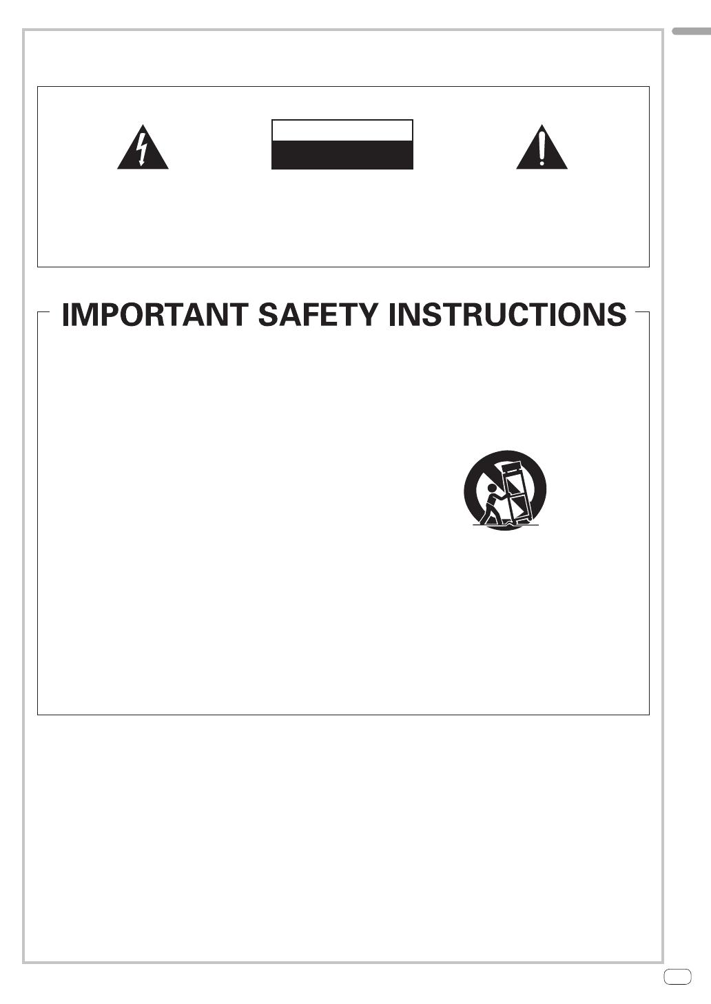
Use only with the cart, stand, tripod, bracket, or
table specified by the manufacturer, or sold with
the apparatus. When a cart is used, use caution
when moving the cart/apparatus combination to
avoid injury from tip-over.
Unplug this apparatus during lightning storms
or when unused for long periods of time.
Refer all servicing to qualified service personnel.
Servicing is required when the apparatus has
been damaged in any way, such as power-supply
cord or plug is damaged, liquid has been spilled
or objects have fallen into the apparatus, the
apparatus has been exposed to rain or moisture,
does not operate normally, or has been dropped.
D3-7-13-69_En
11)
12)
13)
14)
The exclamation point within an equilateral
triangle is intended to alert the user to the
presence of important operating and
maintenance (servicing) instructions in the
literature accompanying the appliance.
The lightning flash with arrowhead symbol,
within an equilateral triangle, is intended to
alert the user to the presence of uninsulated
“dangerous voltage” within the product’s
enclosure that may be of sufficient
magnitude to constitute a risk of electric
shock to persons.
CAUTION:
TO PREVENT THE RISK OF ELECTRIC
SHOCK, DO NOT REMOVE COVER (OR
BACK). NO USER-SERVICEABLE PARTS
INSIDE. REFER SERVICING TO QUALIFIED
SERVICE PERSONNEL.
CAUTION
RISK OF ELECTRIC SHOCK
DO NOT OPEN
IMPORTANT
D3-4-2-1-1b_A1_En
En
4
AFTER-SALES SERVICE FOR PIONEER PRODUCTS
Please contact the dealer or distributor from where you purchased the product for its after-sales
service (including warranty conditions) or any other information. In case the necessary information
is not available, please contact the Pioneer’s subsidiaries (regional service headquarters) listed
below:
PLEASE DO NOT SHIP YOUR PRODUCT TO THE COMPANIES at the addresses listed below for
repair without advance contact, for these companies are not repair locations.
AMERICA
PIONEER ELECTRONICS (USA) INC.
P.O. BOX 1760, LONG BEACH, CA 90801-1760, U.S.A.
EUROPE
PIONEER EUROPE NV
EUROPEAN SERVICE DIVISION
HAVEN 1087, KEETBERGLAAN 1, B-9120 MELSELE, BELGIUM
ASEAN
PIONEER ELECTRONICS ASIACENTRE PTE. LTD.
SERVICE DEPARTMENT
253, ALEXANDRA ROAD #04-01 SINGAPORE 159936
JAPAN AND OTHERS
PIONEER CORPORATION (HEAD OFFICE)
CUSTOMER SUPPORT CENTER
1-1, SHIN-OGURA, SAIWAI-KU, KAWASAKI-SHI, KANAGAWA
212-0031, JAPAN
S016_C1_En
[For American Users and Canadian Users]
En
5
English
D3-4-2-1-6b_A1_En
Laite on liitettävä suojamaadoituskoskettimilla
varustettuun pistorasiaan
For Finland customers
For Norway customers
For Sweden customers
Apparatet må tilkoples jordet stikkontakt
Apparaten skall anslutas till jordat uttag
If you want to dispose this product, do not mix it with general household waste. There is a separate collection system for used
electronic products in accordance with legislation that requires proper treatment, recovery and recycling.
Private households in the member states of the EU, in Switzerland and Norway may return their used electronic products free of charge to
designated collection facilities or to a retailer (if you purchase a similar new one).
For countries not mentioned above, please contact your local authorities for the correct method of disposal.
By doing so you will ensure that your disposed product undergoes the necessary treatment, recovery and recycling and thus prevent potential
negative effects on the environment and human health.
K058b_A1_En
[For European Users]
CAUTION
TO PREVENT THE RISK OF ELECTRIC SHOCK, DO NOT
REMOVE COVER (OR BACK). NO USER-SERVICEABLE
PARTS INSIDE. REFER SERVICING TO QUALIFIED
SERVICE PERSONNEL.
D3-4-2-1-1_B1_En
[For European Users and Others]
NOTE:
This equipment has been tested and found to comply with the limits for a Class B digital device, pursuant to Part 15
of the FCC Rules. These limits are designed to provide reasonable protection against harmful interference in a
residential installation. This equipment generates, uses, and can radiate radio frequency energy and, if not installed
and used in accordance with the instructions, may cause harmful interference to radio communications. However,
there is no guarantee that interference will not occur in a particular installation. If this equipment does cause
harmful interference to radio or television reception, which can be determined by turning the equipment off and on,
the user is encouraged to try to correct the interference by one or more of the following measures:
Reorient or relocate the receiving antenna.
Increase the separation between the equipment and receiver.
Connect the equipment into an outlet on a circuit different from that to which the receiver is connected.
Consult the dealer or an experienced radio/TV technician for help.
D8-10-1-2_A1_En
Information to User
Alterations or modifications carried out without appropriate authorization may invalidate the user’s right to operate
the equipment.
D8-10-2_A1_En
WARNING: This product contains chemicals known to the State of California and other governmental entities to
cause cancer and birth defects or other reproductive harm.
D36-P5_C1_En
IMPORTANT NOTICE
THE MODEL NUMBER AND SERIAL NUMBER OF THIS EQUIPMENT ARE ON THE REAR OR BOTTOM.
RECORD THESE NUMBERS ON YOUR ENCLOSED WARRANTY CARD AND KEEP IN A SAFE PLACE FOR FUTURE
REFERENCE.
D36-AP9-1_A1_En
[For American Users]
En
6
Introduction
Main Features
Coaxial driver reproducing point-source sound with 50 kHz
*HSDOM tweeter.
HSDOM stands for “Harmonized Synthetic Diaphragm Optimum
Method”. All aspects of the diaphragm, including materials,
the shape, and the edges, have been optimized using computer
simulations, realizing ultrahigh frequency playback.
High-stiffness aluminum die-cast cabinet eliminating
unnecessary resonance.
AFAST technology realizes clear sound quality through the
reduction of internal standing waves.
AFAST stands for “Acoustic Filter Assisted System Tuning”.
Technology that controls standing waves and resonant sounds
by adding an acoustic tube inside the speaker enclosure.
Power cord (1)
Operating Instructions (this document)
Rubber leg x 4
Bottom cushion x 6
Names and Functions of Parts
1
2
3
4
1
Coaxial driver
RM-05: 5 inch Aramid fiber woofer
1.5 inch HSDOM tweeter
RM-07: 6.5 inch Aramid fiber woofer
1.5 inch HSDOM tweeter
HSDOM:
[Harmonized Synthetic Diaphragm Optimum Method]
2
POWER / CLIP indicator
Lit white in connection to power ON/OFF. Off when in
Standby.
It will also be lit red when the input level is too high and
causing sound distortion.
In this case, lower the input level.
3
Bass-reflex woofer
4
Groove
Controls the airflow from the bass reflex duct for smooth relay
of the low frequency range.
Front Panel Facilities
* The RM-05 is shown in the illustration. Specifications for the RM-05 and RM-07 are identical apart from the screw holes for the wall
mount bracket.
Confirm All Accessories
RM-05
RM-07
En
7
English
POWER
Unbalanced
RCA
-10dB
-6dB
-4dB +2dB
-2dB 0dB
0dB
Level Low EQ Mid EQ High EQ
XLR
Auto Standby
AC IN
ON
OFF
ON
OFF
-4dB 0dB
-2dB 1dB
-4dB +2dB
-2dB 0dB
5
4
6
b
8
9
a
7
2
3
1
* The RM-05 is shown in the illustration.
1
Screw holes for the wall mount bracket
2
LOW EQ dial
Adjust the frequency response in the low frequency range.
See “Equalizer Settings” on page 9 for more details.
3
MID EQ dial
Adjust frequency attenuation in the approx. 100 Hz to 200 Hz
range.
See “Equalizer Settings” on page 9 for more details.
4
HIGH EQ dial
Adjust the frequency response in the high frequency range.
See “Equalizer Settings” on page 9 for more details.
5
LEVEL dial
Use to adjust the sound level (Volume).
6
RCA INPUT jack (Unbalanced)
7
AUTO STANDBY switch
Use to turn the auto standby function on or off.
When the auto standby function is turned on, the speakers
automatically enter standby mode if no input signal is received
for a certain period of time (approximately 25 minutes) and
power consumption can be reduced. When an input signal is
received while the speakers are in standby mode, the speakers
will automatically resume from standby mode.
The illumination (POWER indicator) on the front panel turns
off when the speakers enter standby mode.
When the input signal is weaker than a certain level, the
speakers may not automatically resume from standby
mode. In such cases, turn off the [
AUTO STANDBY
] switch
to use the speakers.
To force the speakers to resume from standby mode, turn off
the [
POWER
] switch on the rear panel once, and turn it back
on after a few seconds.
8
XLR INPUT connector (Balanced)
The connector’s pin array is as follows:
No. 1 Ground, No. 2 Hot, and No. 3 Cold.
9
AC IN
Connect the accessory power cord here and to an AC power
outlet.
a
Fuse holder
b
POWER switch
Use to turn the power on and off.
Rear Panel Facilities
Cautions for Attaching to Wall Using a Mount Bracket
Use a mount bracket that is capable of supporting the weight of the unit. In regard to retail brackets, please direct any inquiries to
your retailer.
Perform an inspection of the wall etc. prior to performing the mounting, and ensure that it is strong enough to support the weight
of the unit.
Use screws that are suited to the materials of the wall to which the unit is being mounted.
After completing the mounting, be sure to perform a full safety check, and conduct periodic safety checks going forward.
Position of screw holes for the wall mount bracket
RM-05 (M6 10 mm deep 2 locations) RM-07 (M6 10 mm deep 6 locations)
76.2 mm
108 mm
51 mm
70 mm
En
8
Installation and Connections
How to Install
Speakers should ideally be located at 30° angles from the
listening position (together forming a total 60° angle), and
rotated inward to face the listening position.
A speaker’s playback sound is delicately influenced by
conditions in the listening room. To produce optimum listening
conditions, take due consideration of the conditions of your
installation location before beginning actual installation.
Place the speakers at ear level.
60 °
The left and right speakers should be placed at an equal
distance from and bilaterally symmetrical to the listening
position.
Do not block the heat sink section on the back. The resulting
reduction in heat radiation capabilities can lead to a
degradation in performance or cause malfunctions.
You may use the rubber legs and cushions supplied as the situation demands with the unit to tilt the speaker surface upward or place
it vertically.
Angling Speakers
When using a speaker stand etc. to place the speaker surface vertically
Attach the supplied rubber legs (thicker ones) to the indents on the bottom surface.
When placing on a desk etc. with the speaker face tilted upward
Attach the supplied cushions (thinner ones) to the bottom of the unit in order to prevent slippage.
Connections
When making or changing connections, always turn off the
power and disconnect the power cord from its outlet.
Also, be sure to read the operating instructions for the other
components to which you are connecting these speakers.
Do not plug in the power cord until all other connections have
been completed.
Use only the furnished accessory power cord.
Make sure to set the sound level at an appropriate level as the
input signals to the XLR INPUT connector and RCA INPUT
jack will be mixed together, affecting the sound level.
WARNING
Store small parts out of the reach of children and infants. If accidentally swallowed, contact a doctor immediately.
D41-6-4_A1_En
En
9
English
Equalizer Settings
The Tone Control Function
The unit has functionality to adjust frequency response in accordance with the location and environment in which it is placed.
Adjustment is performed using a combination of the three knobs on the rear panel.
The unit is shipped with settings to provide a flat response in an anechoic room. Please adjust the settings to match the environment
in which you place the unit.
Low EQ
A shelving filter is used to adjust the frequency response in the low frequency range. You can choose from +2 dB, 0 dB, –2 dB and –4 dB.
Use if the placement environment of the unit is lacking in the low frequency range, or if reflection from walls etc. is causing the low
frequency range to become too strong.
G%U
+]
50

  





G%U
+]
50

  





Mid EQ
A notch-filter is used to adjust frequency attenuation in the approx. 100 Hz to 200 Hz range. You can choose from 0 dB, –1 dB, –2 dB
and –4 dB.
Use if the effects of a control console or table are making the above range too strong.
High EQ
A shelving filter is used to adjust the frequency response in the high frequency range. You can choose from +1 dB, 0 dB, –1 dB and –2 dB.
Use if the placement environment of the unit is lacking in the high frequency range, or if the high frequency range is too strong.
G%U
+]
50

  





G%U
+]
50

  





G%U
+]
50

  





G%U
+]
50

  





En
10
Additional Information
Troubleshooting
If you think you are experiencing a malfunction with this unit, check the following items.
Also check other devices connected to the
unit. If the problem persists, consult your dealer for service.
On occasion, the unit may fail to operate properly due to static electricity or other external conditions. In this event, disconnect the
power cord and wait for five minutes or more, then reconnect the power cord and check for proper operation.
Symptom Items to Check Remedy
No power Is power cord connected properly? Connect power cord to outlet.
No sound from connected audio
devices, or sound is very small.
Has connected audio device been set properly? Set device’s external input and sound volume properly.
Is connection cable connected properly? Connect cables properly.
Are connectors or plugs dirty? Clean connectors and plugs before connecting.
Is the sound volume set properly? Turn the [
LEVEL
] dial on the rear panel clockwise and
turn up the volume.
Is the power turned on? Turn on the [
POWER
] switch on the rear panel.
Is the auto standby function on? Turn off the [
POWER
] switch on the rear panel once,
wait a few seconds, and then turn it back on.
The POWER indicator (white) does not
come on.
Is the power turned on? Turn on the [
POWER
] switch on the rear panel.
Is the auto standby function on? Turn off the [
POWER
] switch on the rear panel once,
wait a few seconds, and then turn it back on.
Speakers do not resume (turn on) from
standby mode.
Is the level of the input signal low? Increase the level of the input signal.
Turn off the [
AUTO STANDBY
] switch to turn off the
auto standby function.
The sound distorts, or the indicator is lit
red.
Is the level of the input signal too high? Slowly turn the [
LEVEL
] dial on the rear panel
counterclockwise and turn down the volume.
Is the output level of the connected audio device set
properly?
Adjust the output level of the connected audio device
properly.
Feedback (continuous howling sound) Is the sound volume set properly? Slowly turn the [
LEVEL
] dial on the rear panel
counterclockwise and turn down the volume.
Trademarks
Pioneer is a registered trademark of PIONEER CORPORATION.
Other listed company names and a product name are the registered trademark of the companies or trademarks.
En
11
English
Specifications
RM-05 RM-07
Type Bi-amp 2-way active speaker
System Total Capabilities
Frequency Response (–10 dB)
45 Hz to 50 kHz 40 Hz to 50 kHz
Maximum Sound Pressure Level 104 dB SPL (peak @ 1 m) 109 dB SPL (peak @ 1 m)
Input Sensitivity –40 dB to +6 dB
High EQ Can be Adjusted, –2 / –1 / 0 / +1 dB at 10 kHz
Mid EQ Can be Adjusted, –4 / –2 / –1 / 0 dB at 140 Hz
Low EQ Can be Adjusted, –4 / –2 / 0 / +2 dB at 50 Hz
Cross Over Frequency 1.7 kHz 1.6 kHz
Amplifier
Amp Output
LF: 50 W / 4
, Class AB
HF: 50 W / 4
, Class AB
LF: 100 W / 4
, Class AB
HF: 50 W / 4
, Class AB
Input connectors (balanced input) XLR × 1
Input connectors (unbalanced input) RCA × 1
Impedance 10 k
Speaker
Enclosure Bass reflex/Aluminum die-cast
Woofer (LF driver) 13 cm (5 in.) cone 16.5 cm (6.5 in.) cone
Tweeter (HF driver) 3.8 cm (1.5 in.) hard dome 3.8 cm (1.5 in.) hard dome
Power unit/other
Supported voltages* 100 V (50 Hz/60 Hz), 110 V to 120 V (50 Hz/60 Hz), 220 V to 240 V (50 Hz/60 Hz)
Power consumption 142 W 195 W
Power consumption during standby mode
0.3 W or less 0.3 W or less
External dimensions W × H × D
203 mm x 281 mm x 225 mm
8.0 in. x 11.1 in. x 8.9 in.
244 mm x 337 mm x 260 mm
9.6 in. x 13.3 in. x 10.2 in.
Weight 9.3 kg (20.5 lbs) 12.3 kg (27.1 lbs)
* Differs depending on the region of use.
Specifications and design subject to possible modification without notice, due to improvements.
© 2015 PIONEER CORPORATION. All rights reserved.
࠾ၥྜࡏඛ㸸ࠉ3LRQHHU'-ࢧ࣏࣮ࢺࢭࣥࢱ࣮
ӒᎣ޷ӌԥ४ϵѨ
ѯᢋѯіҀϲ෺ୣ࿆ӏ ĵıĸ Ĺ
TEL: 886-(0)2-2657-3588
ӒᎣႬφȞॸ෬ȟԥ४ϵѨ
ॸ෬Οᓹߞؔᢋၿ ĺıĺġဵ Ķġዃ
TEL: 852-2848-6488
PIONEER ELECTRONICS DE MEXICO S.A. DE C.V.
Blvd.Manuel Avila Camacho 138 10 piso Col.Lomas de Chapultepec,
Mexico, D.F. 11000 TEL: 55-9178-4270
PIONEER INDIA ELECTRONICS PRIVATE LTD.
216, Second Floor, Time Tower, M.G. Road, Sector 28, Gurgaon 122001,
Haryana, India TEL: +91-124-463-6100
PIONEER CORPORATION
1-1, Shin-ogura, Saiwai-ku, Kawasaki-shi, Kanagawa 212-0031, Japan
Корпорация Пайонир
1-1, Син-Огура, Сайвай-ку, г. Кавасаки, префектура Канагава, 212-0031, Япония
PIONEER EUROPE NV
Haven 1087, Keetberglaan 1, B-9120 Melsele, Belgium TEL: 03/570.05.11
PIONEER ELECTRONICS (USA) INC.
P.O. BOX 1720, Long Beach, California 90801-1720, U.S.A. TEL: (800) 421-1404
PIONEER ELECTRONICS ASIACENTRE PTE. LTD.
253 Alexandra Road, #04-01, Singapore 159936 TEL: 65-6472-7555
PIONEER ELECTRONICS AUSTRALIA PTY. LTD.
5 Arco Lane, Heatherton, Victoria, 3202, Australia, TEL: (03) 9586-6300
PIONEER ELECTRONICS (THAILAND) CO., LTD.
17th Fl., KPN Tower, 719 Rama 9 Road, Bangkapi, Huaykwang, Bangkok 10310 TEL: 66-2-717-0777
© 2015 PIONEER CORPORATION.All rights reserved.
<DRC1403-B>
Printed in China
RM-05/RM-07
Сделано в Китае
SAMPLE
  • Page 1 1
  • Page 2 2
  • Page 3 3
  • Page 4 4
  • Page 5 5
  • Page 6 6
  • Page 7 7
  • Page 8 8
  • Page 9 9
  • Page 10 10
  • Page 11 11
  • Page 12 12
  • Page 13 13
  • Page 14 14
  • Page 15 15
  • Page 16 16
  • Page 17 17
  • Page 18 18
  • Page 19 19
  • Page 20 20
  • Page 21 21
  • Page 22 22
  • Page 23 23
  • Page 24 24
  • Page 25 25
  • Page 26 26
  • Page 27 27
  • Page 28 28
  • Page 29 29
  • Page 30 30
  • Page 31 31
  • Page 32 32
  • Page 33 33
  • Page 34 34
  • Page 35 35
  • Page 36 36
  • Page 37 37
  • Page 38 38
  • Page 39 39
  • Page 40 40
  • Page 41 41
  • Page 42 42
  • Page 43 43
  • Page 44 44
  • Page 45 45
  • Page 46 46
  • Page 47 47
  • Page 48 48
  • Page 49 49
  • Page 50 50
  • Page 51 51
  • Page 52 52
  • Page 53 53
  • Page 54 54
  • Page 55 55
  • Page 56 56
  • Page 57 57
  • Page 58 58
  • Page 59 59
  • Page 60 60
  • Page 61 61
  • Page 62 62
  • Page 63 63
  • Page 64 64
  • Page 65 65
  • Page 66 66
  • Page 67 67
  • Page 68 68
  • Page 69 69
  • Page 70 70
  • Page 71 71
  • Page 72 72
  • Page 73 73
  • Page 74 74
  • Page 75 75
  • Page 76 76
  • Page 77 77
  • Page 78 78
  • Page 79 79
  • Page 80 80

Pioneer DJ RM-05 User manual

Category
Supplementary music equipment
Type
User manual
This manual is also suitable for

Ask a question and I''ll find the answer in the document

Finding information in a document is now easier with AI