Page is loading ...

Part # 1844063 (08/06) Page 1
INSTALLATION, OPERATING
& SERVICE INSTRUCTIONS
FOR THE
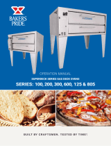
GARLAND GPD SERIES GAS PIZZA OVENS
FOR YOUR SAFETY
DO NOT STORE OR USE GASOLINE OR OTHER
FLAMMABLE VAPORS OR LIQUIDS IN THE
VICINITY OF THIS OR ANY OTHER APPLIANCE.
WARNING:
IMPROPER INSTALLATION, ADJUSTMENT,
ALTERATION, SERVICE OR MAINTENANCE CAN
CAUSE PROPERTY DAMAGE, INJURY OR DEATH.
READ THE INSTALLATION, OPERATION AND
MAINTENANCE INSTRUCTIONS THOROUGHLY
BEFORE INSTALLING OR SERVICING
THIS EQUIPMENT.
PLEASE READ ALL SECTIONS OF THIS MANUAL AND RETAIN FOR FUTURE REFERENCE.
THIS PRODUCT HAS BEEN CERTIFIED AS COMMERCIAL COOKING EQUIPMENT AND MUST BE INSTALLED
BY PROFESSIONAL PERSONNEL AS SPECIFIED.
IN THE COMMONWEALTH OF MASSACHUSETTS THIS PRODUCT MUST BE INSTALLED BY A LICENSED
PLUMBER OR GAS FITTER. APPROVAL NUMBER: G-1-07-05-28
For Your Safety:
Post in a prominent location, instructions to be followed in the event the user smells gas. is information shall be
obtained by consulting your local gas supplier.
Users are cautioned that maintenance and repairs must be performed by a Garland authorized service agent using genuine
Garland replacement parts. Garland will have no obligation with respect to any product that has been improperly installed,
adjusted, operated or not maintained in accordance with national and local codes or installation instructions provided
with the product, or any product that has its serial number defaced, obliterated or removed, or which has been modified
or repaired using unauthorized parts or by unauthorized service agents. For a list of authorized service agents, please refer
to the Garland web site at http://www.garland-group.com. e information contained herein, (including design and parts
specifications), may be superseded and is subject to change without notice.
Continuous product improvement is a Garland policy, therefore design and specifications are subject to change without notice.
GARLAND COMMERCIAL INDUSTRIES
185 East South Street
Freeland, Pennsylvania 18224
Phone: (570) 636-1000
Fax: (570) 636-3903
GARLAND COMMERCIAL RANGES,
LTD.
1177 Kamato Road, Mississauga, Ontario L4W 1X4
CANADA
Phone: 905-624-0260
Fax: 905-624-5669
Enodis UK LTD.
Swallowfield Way, Hayes, Middlesex UB3 1DQ ENGLAND
Telephone: 081-561-0433
Fax: 081-848-0041
Part # 1844063 (08/06) © 2005 Garland Commercial Industries, Inc.

Part # 1844063 (08/06)Page 2
IMPORTANT INFORMATION
WAR NING:
is product contains chemicals known to the State of California to cause cancer and/or birth defects or other
reproductive harm. Installation and servicing of this product could expose you to airborne particles of glass wool/
ceramic fibers. Inhalation of airborne particles of glass wool/ceramic fibers is known to the State of California to
causes cancer. Operation of this product could expose you to carbon monoxide if not adjusted properly. Inhalation
of carbon monoxide is known to the State of California to cause birth defects or other reproductive harm.
Keep appliance area free and clear from combustibles

Part # 1844063 (08/06) Page 3
TABLE OF CONTENTS
Important Information ................2
Dimensions And Specifications
GPD Series ........................ 4
Installation ........................ 5
Rating Plate ............................5
Gas Connections ....................... 5
Installation Clearances ................... 6
Preparation: ........................... 6
Ventilation: ............................ 6
Air Supply ............................ 6
Installing Under Ventilation Canopy: ........ 7
Installing With Direct Ventilation .......... 7
Assembly Instructions ............... 7
Leg Installation ......................... 7
Hearth Installation ...................... 7
Double Deck Assembly ................... 8
Gas Connection: ........................ 8
Adjustments ........................ 9
Gas Pressure Adjustments: ................ 9
Flame & Air Mixture Adjustment: .......... 9
By-pass Flame Adjustment: ............... 10
Calibration: .......................... 10
Flame Diverters ........................11
Operation .........................11
Break-in: ..............................11
Lighting/shutdown Instructions: ........... 12
Cleaning ......................... 12
Oven Exterior: ........................ 12
Oven Interior: ......................... 12
Core Plates: ........................... 12
Troubleshooting Guide .............. 13

Part # 1844063 (08/06)Page 4
DIMENSIONS AND SPECIFICATIONS GPD SERIES
3"
[76mm]
7-15/16"
[201mm]
12-1/2"
[318mm]
45-1/4"
[1149mm]
8"
[203mm]
7-21/32"
[195mm]
3/4"N.P.T.
[19mm]
GASINLET
14-1/2"
[368mm]
23-3/8"
[594mm]
24-21/32"
[626mm]
28-1/2"
[724mm]
DECK
36-1/2"
[927mm]
REAR&SIDE
GASINLET
DIA6"
[152mm]
74-1/32"
[1880mm]
23-3/8"
[594mm]
51-7/8"
[1318mm]
DECK
31"
[787mm]
24-21/32"
[626mm]
45"
[1143mm]
DECK
53"
[1346mm]
67-5/32"
[1705mm]
DIA6"
[152mm]
Installation Notes:
Non-Combustible &
Combustible Wall
Clearances
Sides Back
1” (25mm) 6” (152mm)
Entry Clearance:
Crated Uncrated
35”
(889mm)
26”
(660mm)
Manifold
Operating Pressure:
Natural Propane
6” WC
(15mbar)
10” WC
(25mbar)
INPUT SPECIFICATIONS
Natural Or Propane
MODEL
BTU/HR
KW
GAS
INLET
GPD48 96,000 28.1 3/4" N.P.T.
GPD60 122,000 35.7 3/4" N.P.T.
GPD48-2 192,000 56.2 1" N.P.T.
GPD60-2 244,000 71.4 1" N.P.T.
Ratings shown are for natural gas
installations up to 2000 feet (610m)
above sea level. BTU input ratings must
be de-rated for high altitude installations.
Specify altitude of product if over 2000
feet (610m)
is product is not approved for residential
use
MODEL
NUMBER
Interior Dimensions: In (mm)
Exterior Dimensions In (mm)
W H D W H (w/NSF legs) D
GPD48 48 (1220) 8 (203) 36 (914) 63 (1600) 52-3/4 (1340) 45-1/4 (1149)
GPD60 60 (1524) 8 (203) 36 (914) 75 (1905) 52-3/4 (1340) 45-1/4 (1149)
GPD48-2 48 (1220) 8 (203) 36 (914) 63 (1600) 62-1/2 (1588) 45-1/4 (1149)
GPD60-2 60 (1524) 8 (203) 36 (914) 75 (1905) 62-1/2 (1588) 45-1/4 (1149)

Part # 1844063 (08/06) Page 5
INSTALLATION
1. Damage Check: check carton or crate for possible
damage incurred in shipping. After carefully
uncrating, check for “concealed” damage. Report
any damage immediately to your carrier.
2. e correct type of gas for which the unit was
manufactured is noted on the rating plate, and this
type of gas must be used.
3. e gas pressure must be checked when the unit is
installed, to ensure that the unit gas pressure is the
same as specified on the rating plate. If necessary
pressure adjustments can be made at the pressure
regulator, supplied on each unit.
4. Have a qualified gas technician check the gas
pressure to make certain that existing gas facilities
(meter, piping, etc.) will deliver the BTU’s of gas
required at the unit with no more than ½” water
column pressure drop. When checking pressure, be
certain that all the equipment on same gas line is
turned to the “ON” position.
5. Make certain that the new piping, joints and
connections have been made in a clean manner and
have been purged, so that the piping compound,
chips, etc will not clog pilots, valves and / or
controls. Use pipe joint sealant that is certified for
use with LP gas.
6. WARNING; check gas connections for leaks,
using soap solution or similar means. DO NOT
CHECK WITH AN OPEN FLAME.
Rating Plate
All burner-input ratings are shown on the serial plate
located on the right side panel of the appliance.
When corresponding with the factory or your local
authorized factory service center regarding service
problems or replacement parts, be sure to refer to the
particular unit by the correct model number (including
the prefix and suffix letters and numbers) and the
warranty serial number. e rating plate affixed to the
unit contains this information.
We suggest installation, maintenance and repairs should
be performed by your local authorized service agency
listed in your information manual pamphlet.
In the event you have any questions concerning the
installation, use, care or service of the product, write or
call our Product Service Department.
is product must be installed by professional personnel
as specified. Garland/U.S. Range products are not
approved or authorized for home or residential use,
but are intended for commercial applications only.
Garland / U.S. Range will not provide service, warranty,
maintenance or support of any kind other than in
commercial applications.
Gas Connections
e inlet manifold size for connection to the main gas
supply is () ¾” NPT inlet for each deck.
e importance of proper installation of Commercial
Gas cooking Equipment cannot be over stressed. Proper
performance of the equipment is dependent, in great
part, on the compliance of the installation with the
manufacturer’s specifications. Installation must conform
to local codes with the Nation fuel code, ANSI Z.,
Natural Gas Installation code, CAN/CGA-B., or
the Propane Installation code, CAN/CGA-B., as
applicable, including:
1. e appliance and its individual shut-off valve must
be disconnected from the gas supply piping system
during any pressure testing of that system at test
pressures in excess of ½ psi (3.45 kPa).
2. e appliance must be isolated from the gas supply
piping system by closing its individual manual
shut-off valve during any pressure testing of the gas
supply piping system at test pressures equal to or
less than ½ psi (3.45 kPa).
Before assembly and connections, check gas supply.
A. e type of gas for which the unit is equipped is
stamped on the data plate located behind lower
front panel. Connect a unit stamped “NAT” only
to natural gas; connect those stamped “PRO” only
to propane gas.

Part # 1844063 (08/06)Page 6
B. If it is a new installation, have gas authorities
check meter size and piping to assure that the unit
is supplied with sufficient amount of gas pressure
required to operate the unit.
C. If it is additional or replacement equipment, have
gas authorities check pressure to make certain that
existing meter and piping will supply fuel at the
unit with not more than ½” water column pressure
drop.
NOTE: When checking pressure be sure that all
other equipment on the same gas line is on. A pressure
regulator is supplied with GARLAND Pizza Ovens.
Regulator is preset to deliver gas at pressure shown on
the rating plate.
Installation Clearances
Minimum clearance for combustible and Non-
Combustible Construction : ” (mm) sides and
” (mm) rear. Suitable for installation on combustible
floors. Legs must be installed.
Preparation
1. Carefully remove unit from carton or crate. Burner
tie wires and other packing material should be
removed from units. On stainless steel units, the
protective material covering the stainless steel
should be removed immediately after the unit is
installed.
2. is unit must be mounted on the factory-supplied
legs when installed. Refer to section titled LEG
INSTALLATION for details.
3. Provide adequate clearances for proper operation
and servicing of the appliance.
4. For your safety: keep the appliance area free and
clear from combustibles.
5. ese units must be installed under an adequate
ventilation system. Refer to sections titled
“Ventilation” and “Air Supply” for further
instructions.
Ventilation
is appliance must be installed in a location in which the
facilities for ventilation permit satisfactory combustion of
gas and proper venting. Proper ventilation is imperative
for good operation of the appliance. e ideal method of
ventilating equipment is the use of a properly designed
ventilating canopy, which should extend at least ”/mm
beyond all sides of the appliance (except against the wall
if the canopy is a wall installation). is is usually part
of a mechanical exhaust system
Air Supply
1. It is necessary that sufficient room air ingress be
allowed to compensate for the amount of air
removed by any ventilating system. Otherwise
a subnormal atmospheric pressure will occur,
affecting the appliance operation adversely and
causing undesirable working conditions.
2. Appliances shall be located so as not to interfere
with proper circulation of air within the confined
space. All gas burners and pilots require sufficient
air to operate.
3. Large objects should not be placed in front of the
appliance, which might obstruct the airflow through
the front. Do not obstruct the flow of combustion
and ventilation air.
4. Do not permit fans to blow directly at the appliance,
and wherever possible, avoid open windows adjacent
to the appliance sides and back; also wall type fans
which create air cross-currents within the room.
INSTALLATION Continued
DRAFT DIVERTER
FLUE CAP

Part # 1844063 (08/06) Page 7
INSTALLATION continued
Termination Less than 10 feet (3 meters) from ridge Termination More than 10 feet (3 meters) from ridge
Less than 10 feet (3 meters)
More than 10' (3 meters)
2' (60cm) Min.
3' (90cm) Min.
3' (90cm) Min.
Installing Under Ventilation Canopy:
Too strong a pull through the exhaust system will pull
heat out of the oven too rapidly and cause uneven baking
(strong bottoms and light tops).
All ovens, operating under a ventilating canopy should be
equipped with a canopy flue diverter assembly (supplied
to offset too strong a pull.
Installing with Direct Ventilation
Wherever a direct flue is unavoidable, it is necessary
that:
1. e draft diverter shipped with the oven is
installed.
2. An adequately sized draft regulator (barometric
damper) must be installed in the flue line as close
to the oven connection as possible.
An adequately sized prefabricated metal vent should rise
at least feet (m) above the roof of the building in
which it is installed, or feet (m) above any proximate
higher structure, and should be equipped with a well
designed vent cap.
Never, under any circumstances, install a damper or
place steel wool in an oven flue.
ASSEMBLY INSTRUCTIONS
Leg Installation
On single deck units, tip oven section units back. On
double-deck units, tip lower oven section ONLY on its
back. Each leg is secured with four /” (mm) hex
head bolts, threaded into nuts located on the underside
of the base angle. When both front legs are installed,
lift and block up rear of unit. Install rear legs.
Hearth Installation
NOTE: Because of the weight of the hearth plates, be
very careful to avoid injury to yourself and to shelf joint
edges, when sliding shelf halves into the oven.
To install hearth core plates or steel hearth assembly,
proceed as follows:

Part # 1844063 (08/06)Page 8
ASSEMBLY INSTRUCTIONS Continued
1. Slide the wooden frame out of the oven.
2. Before installing the hearth core plates or steel
hearth assembly, be sure that the bottom heat
deflectors are properly positioned with the treaded
side (bumps) in the up position.
3. If the oven is supplied with a steel hearth assembly,
place the hearth spacers (with the flat side in the
up position) on the extreme left and right sides of
the oven resting on the heat deflectors. Making sure
the hearth spacers are not disturbed, slide the steel
hearth assembly into the oven.
4. If oven is supplied with hearth core plates, slide the
plates into the oven.
GPD-48 is supplied with (2) two hearth core plates.
GPD-60 is supplied with (3) three hearth core plates.
5. Installation instruction for Hearth.
a. Place a screwdriver, or a similar prying
device, between the core plate and hearth
frame support, (being careful not to chip
the core plate) then place two spacer clips
(PN G03086-1-9) between the core plate and
the hearth frame support. (See instructions
sheet – PN 1917401) 6” from front & 6” from
rear.
b. Place a screwdriver between the back of the
right core plate and hearth frame support. Pry
the core plate forward, away from the hearth
support and place a clip within the space
centered on each core plate.
c. Repeat step 2 for the left core plate
d. Repeat step 3 for the center core plate for 60”
unit.
Double Deck Assembly
1 Secure legs to lower section
2. Remove stainless steel top trim strip from lower
unit if not already removed.
3. Tip upper unit backward. Remove vent patch at
lower rear if not if not already removed.
4. Place 1” x 4” x 65” (25mm x 100mm x 1650mm)
long piece of lumber across the rear top of oven to
prevent stacks from misarranging.
5. Raise the top oven section up and onto the lower
oven section.
6. Carefully remove piece of lumber ensuring lower
section vent collar inserts into upper section vent
hole.
Gas Connection
1. e appliance must be isolated from the gas supply
piping system by closing its manual shut-off valve
during any pressure testing of the gas supply piping
system at test pressure equal to or less that ½ psig.
(3.45 kpa.).
2. e appliance and its shut off valve must be
disconnected from the gas supply piping system
during any pressure testing of that system at test
pressures in excess of ½ psig. (3.45 kpa.).
NOTE: e ovens should not be installed on the same
line with space heaters, broilers or other equipment
with high intermittent demand.
3. When making gas connections, uses a pipe joint
compound that is resistant to the action of liquefied
petroleum gases.
4. Each oven is supplied with two possible gas
connection locations. One is located on the right
side and the other is located on the right rear
corner.
5. e right side connection is plugged with a ¾
counter sunken plug. If this connection is used, you
must cap the rear connection.
6. e gas pressure regulator is part of the combination
valve and is adjusted to yield a pressure of 6.0” water
column for natural gas and 10” water column for
propane gas.

Part # 1844063 (08/06) Page 9
ASSEMBLY INSTRUCTIONS Continued
7. A separate shut-off valve for each oven must be
provided. It should be as close as possible to the
place where the gas line goes into the oven. It must
be located so that it is easily accessible. A handle or
wrench should be chained to the valve where it will
always be at hand.
8. For a stack of two ovens, two shut-off valves, one
for each oven must be provided.
ADJUSTMENTS
Gas Pressure Adjustments
All GPD Series ovens are equipped with fixed orifices
and cannot be adjusted for gas flow: If necessary, pressure
adjustments can be made at the pressure regulator
(located on the combination gas valve).
A pressure tap is supplied with the unit and it is installed
on the manifold, downstream of the main valve. e gas
pressure must be checked when the unit is installed, to
ensure that the unit gas pressure is the same as specified
on the rating plate.
IMPORTANT:
All gas burners and pilots need sufficient air to
operate and large objects should not be placed
in front of this oven, which would obstruct the
airflow through the front.
Objects should not be placed on main rear of oven
while in use.
Flame & Air Mixture Adjustment
After the pilot burner is ignited, when heat is desired, turn
gas cock dial to “ON” position and set the thermostat
dial to the desired temperature. e oven burner flame
should always have a blue appearance. is indicates a
3/4 NIPPLE
3/4" COUPLING
3/4" x 3/4" x 1" TEE
6 1/2" NIPPLE
3/4" NIPPLE
3/4" COUPLING
1" NPT 90° STREET ELBOW
5 3/4" NIPPLE
3/4" UNION
3/4" NPT 90° STREET ELBOW
3/4" NPT 90° STREET ELBOW

Part # 1844063 (08/06)Page 10
good mixture of air and gas. When using LP gas the
flame will have a blue yellow appearance. Follow steps
thru to adjust the flame for good quality.
1. Loosen the small knurled locking disk.
2. Turn the large adjusting disk towards the air mixture
throat to reduce the opening. is restricts the
amount of air, causing the flame to turn yellow.
3. Turn the adjusting disk gradually out, away from
the air mixer throat, allowing more air into the air
mixer until the yellow disappears and a sharp blue
flame appears.
4. When the flame turns blue and spreads out, turn
the locking disk tight against the adjusting disk.
ere may be intermittent yellow-orange flame
noticed. is is caused by dust particles burning in
the Flame. Should the burners fail to light, check
to see if there is a problem with any or all of the
following.
A. e gas supply: If there are other gas appliances on
the same supply line, shut them off temporarily and
see if the flame comes back on, or if it fluctuates as
other gas appliances are turned on and off. If so, it
would indicate overloading of the gas supply or a
faulty gas pressure regulator. You should contact a
qualified service agency or the local gas company to
check the gas supply.
B. Dirty burner orifice or ports: With the oven cold,
use a thin wire to check that the spud orifice (nozzle)
is clear. If necessary, loosen and remove the spud.
Be careful when cleaning not to enlarge the hole.
en, using a wire or thin nail, clear the burner
ports of carbon deposits or other restrictions.
Periodically, after breaking the ovens in, check the burner
flame and readjust the air mixture if needed. Black soot
on the oven doors or in the burner compartment may
indicate that not enough air is mixing with the gas. If
this case back off the air adjustment disk until the proper
flame and color is set.
By-Pass Flame Adjustment
e by-pass in the thermostat is a small gas supply
through the control that is independent of the dial
setting. It is controlled strictly by the Adjusting Screw.
is small gas supply maintains a minimum flame or
the burner(s), helping to maintain the heat in the oven
and assisting in recovery. is adjustment is best done
when the oven is being heated for the day’s business. To
adjust the by-pass flame follow steps thru .
1. Turn the oven on and set the thermostat to the
desired temperature.
2. Allow the oven to pre-heat until the burner flame
begins to throttle down.
3. At this point, turn the thermostat dial all the way
down. is ensures that the thermostat is in the by-
pass mode. ere should now be a small steady flame
remaining across the burner without flickering or
going out.
NOTE: It may be necessary to turn the thermostat back
up to relight the burner(s) if there is not flame present.
4. Using a small screwdriver, reach through the access
hold on the control panel to the left of the thermostat
knob. Turn the by-pass adjustment screw to raise
or lower the by-pass flame as required. Counter-
clockwise raises the flame, clockwise lowers the
flame. Take care not to turn the screw out too far
as that will allow gas to leak around the adjustment
screw.
Calibration
1. Field calibration is seldom necessary and should not
be attempted unless experience with cooking results
definitely proves that the control is not maintaining
the temperature to which the dial is set.
2. Place the thermocouple of the test instrument
or reliable mercury thermometer in the center
of the oven approximately one or two inches
(25mm – 50mm) above the hearth. Do not place the
thermocouple directly in contact with the hearth.
ADJUSTMENTS Continued

Part # 1844063 (08/06) Page 11
ADJUSTMENTS Continued
3. Set the thermostat temperature dial to 500 degrees
F (260 degrees C) and allow the oven temperature
to stabilize. e thermostat must be allowed to
cycle twice before taking a test reading.
4. Check the temperature when the burner just cycles
off after the second cycle, compare the reading of
thermocouple or thermometer with thermostat
setting.
5. If the two do not agree (plus or minus 15 degrees
F (8 degrees C)), carefully remove the thermostat
dial, not disturbing dial settings.
6. Hold calibration plate and loosen the two calibration
screws until the plate can be moved independently
of the control.
7. Turn calibration plate so that the instrument of
thermometer reading is in line with the indicator
mark. Hold plate and tighten screws firmly.
8. Replace dial.
9. NOTE: If the above adjustment is prevented by
the two loosened calibration lock screws being in
contact with the ends of the screw clearance plate to
the proper location, reassembly screws in the other
tapped holes designed for them.
NOTE: NO ATTEMPT TO RECALIBRATE
THE OVEN CONTROL SHOULD BE MADE
WITHIN THE WARRANTY PERIOD IF THE
TEMPERATURE IS WITHIN ± DEGREES
FAHRENHEIT OF THE DIAL SETTING.
RECALIBRATION SHOULD BE MADE IF THE
CONTROL IS OUT MORE THAN ± DEGREES
FAHRENHEIT AND LESS THAN ± DEGREES
FAHRENHEIT. IF THE CONTROL IS OUT MORE
THAN DEGREES FAHRENHEIT FROM THE
DIAL SETTING, THE CONTROL WILL BE
REPLACED UNDER WARRANTY, (WITHIN
THE WARRANTY PERIOD).
Flame Diverters
Flame diverters distribute the heat evenly below the deck.
ey must be in good condition and properly placed in
the burner chamber in order to be effective. Damaged or
improperly installed flame diverters adversely affect the
oven performance. Check them periodically and replace
as needed. Make sure that the “V” shaped diverters are
pushed all the way to the back of the oven as far as they
will go.
OPERATION
Break-In
1. Once the equipment has been installed and tested
by qualified professional personnel, the oven is
ready for operation.
2. Many of the parts used in the oven have a thin
protective oil covering. is oil should be burned
off before the oven is used for the production of
food products. It is normal for the unit to smoke
while burning off excess oil. Washing the deck of
the oven with a damp clean cloth and mild soap
solution will remove some of the protective oil
coating.
3. Select a temperature of 300 degrees F (150
degrees C) and turn the gas cock dial to the ON
position.
4. Allow the oven to warm to 300 degrees F (150
degrees C) and keep it there for FIVE HOURS, or
at least until all smoke and fumes have disappeared.
e smoke and fumes are from moisture in the deck
and insulation and a light coat of oil.
5. Turn the thermostat knob to between 475 degrees
F (250 degrees C). Allow the oven to warm up to
your selected temperature for 1 to 1 ½ hours.

Part # 1844063 (08/06)Page 12
CLEANING
6. When the oven has reached the selected temperature,
experiment until you get the feel of the oven and the
speed of the bake. In case of some initial unevenness
in the baking, have patience for a few days until the
oven cures
Lighting/Shutdown Instructions
1. Open control panel door located on right hand side
of unit. To access combination gas control.
2. Turn gas cock on combination control to the “OFF”
position. Wait 5 minutes.
3. Turn gas cock on combination control to the
“PILOT” position.
4. Depress gas cock and light pilot burner.
5. Hold gas cock depressed for one minute after pilot
has been ignited, then release. Pilot should continue
to burn.
6. If pilot does not continue to burn after releasing
gas cock, repeat steps 2 thru 5 or have a qualified
serviceman check the system. Do not allow anyone
else to attempt repairs.
7. Once pilot is lit, turn gas cock to the “ON” position.
It is not necessary to repeat lighting procedure
unless the pilot is extinguished by any cause.
8. To shut down unit, turn gas cock on combination
control to the “OFF” position
Oven Exterior
Painted Surfaces should be cleaned when cool, using
a mild soap and warm water solution on a sponge or
soft clean cloth. Rinse and dry thoroughly with a soft
clean cloth.
Stainless Steel Surfaces usually respond to cleaning as
noted above. Stubborn stains or heat tint may require
the use of a commercial type cleaner, such as Penny
Brite or stainless steel pad. Always rub in the direction
of the polished lines. Rinse thoroughly with fresh water
and wipe dry.
Oven Interior
Aluminized Steel Surfaces Should be cleaned with a
damp soft cloth and mild household detergent.
Core Plates
CAUTION: e use of water to cool down or clean
core plates will void warranty.
To clean core plates, set thermostat dial to degrees
F ( degrees C) at the end of the cooking day and
allow thermostat to cycle for one hour. When the oven
has cooled, cooking residue will be carbonized and can
be removed by sweeping with a stiff brush. Stubborn
residue can be loosened with a scraper.
OPERATION Continued

Part # 1844063 (08/06) Page 13
Problem Causes Solutions
Hot Spots in Deck Flame diverters not installed properly Push all the way to the back of oven
Flame diverters warped or damaged May need replacing
Bottoms cook before top Deposit on deck Clean deck
Low production oven idling Turn temperature up after loading pizza.
Make sure to turn the temperature down
after bake is compete
By-pass flame too high Adjust by-pass flame
Improper damper position Adjust dampers
Bottoms become light during
periods of heavy production
Improper damper position Close dampers
Placement of pizza Change placement
By-pass flame low Increase by-pass flame
Color overall dark High temperature Lower temperature
Pizza left in too long Reduce bake time
By-pass flame high Reduce by-pass flame
Thermostat Check actual temperature; call for
service
Color overall light Short bake time Bake longer
Lower temperature Increase temperature
Dough Check dough for freshness
Pre-heat time short Allow for adequate pre-heating
Top color light Damper closed Open damper
Oven idles during slow periods Increase temperature to bake, reduce
again when bake is finished
Burner flame yellow/soft/lazy Not enough air mixing Open (adjust) air shutter
Low gas pressure Adjust pressure
Flame lifts off burner ports Too much air mixed with gas Close (adjust) air shutter
Flashes back in burner Gas pressure too high Adjust pressure
Pops excessively when turned off Wrong orifice in unit Replace with proper orifice
Burner flame too large Unit over gassed or wrong orifice Check gas pressure and orifice size
Burner flame shuts off when oven
reaches set temperature
By-pass set too low Adjust by-pass
TROUBLESHOOTING GUIDE

Pièce nº 1844063 (07/05) Page 3
TABLE DES MATIÈRES
Informations Importantes . . . . . . . . . . . . . .2
Dimensions And Specifi cations
GPD Series . . . . . . . . . . . . . . . . . . . . . . . . .4
Installation . . . . . . . . . . . . . . . . . . . . . . . . .5
Plaque Signalétique . . . . . . . . . . . . . . . . . . . . . .5
Branchements Du Gaz . . . . . . . . . . . . . . . . . . . .5
Dégagements D’installation . . . . . . . . . . . . . . . .6
Préparation . . . . . . . . . . . . . . . . . . . . . . . . . . . . .6
Ventilation . . . . . . . . . . . . . . . . . . . . . . . . . . . . .6
Alimentation En Air . . . . . . . . . . . . . . . . . . . . .6
Installation Sous Une Hotte De Ventilation . . . .7
Installation Avec Une Ventilation Directe . . . . . .7
Instructions D’assemblage . . . . . . . . . . . . .8
Installation Des Pieds . . . . . . . . . . . . . . . . . . . . .8
Installation De La Sole . . . . . . . . . . . . . . . . . . .8
Assemblage Du Four À Deux Sections . . . . . . . .8
Branchement De Gaz: . . . . . . . . . . . . . . . . . . . . .9
Réglages . . . . . . . . . . . . . . . . . . . . . . . . . . .10
Réglages de pression du gaz . . . . . . . . . . . . . . .10
Réglages De Flamme Et Du Mélange D’air . . . 10
Réglage De La Flamme De Dérivation: . . . . . . 11
Étalonnage . . . . . . . . . . . . . . . . . . . . . . . . . . . . 11
Défl ecteurs De Flammes . . . . . . . . . . . . . . . . . .12
Fonctionnement . . . . . . . . . . . . . . . . . . . . .12
Rodage . . . . . . . . . . . . . . . . . . . . . . . . . . . . . .12
Instructions D’allumage Et D’arrêt . . . . . . . . . .13
Nettoyage . . . . . . . . . . . . . . . . . . . . . . . . .13
Extérieur Du Four . . . . . . . . . . . . . . . . . . . . . .13
Intérieur du four . . . . . . . . . . . . . . . . . . . . . . .13
Plaques de sole . . . . . . . . . . . . . . . . . . . . . . . . .13
Guide De Dépannage . . . . . . . . . . . . . . . .14
/