00-99-000906/0709
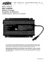
Model / Modelo / Modèle: INC-700A
Power Supply/Battery Charger
Fuente de Poder/Cargador de Baterías
Source d’Énergie/Chargeur de Batterie
Voltage / Tensión / Tension: 12
Amperage / Amperaje / Ampérage: 4, 20, 70
READ THE ENTIRE MANUAL BEFORE USING THIS PRODUCT. •
FAILURE TO DO SO CAN RESULT IN SERIOUS INJURY OR DEATH.
LEA EL MANUAL COMPLETO ANTES DE UTILIZAR ESTE •
PRODUCTO. CUALQUIER FALLA PODRÍA RESULTAR EN SERIAS
LESIONES O PODRÍA SER MORTAL.
LIRE ENTIÈREMENT LE GUIDE AVANTD’UTILISER CE PRODUIT. •
L’ÉCHEC DE FAIRE AINSI PEUT S’ENSUIVRE DANS LA BLESSURE
SÉRIEUSE OU LA MORT.
OWNER’S MANUAL•
MANUAL DEL USUARIO•
GUIDE D’UTILISATION•
™
Page is loading ...

TABLE OF CONTENTS
SECTIONE PAGE
IMPORTANT SAFETY INSTRUCTIONS 2
PERSONAL PRECAUTIONS 3
PREPARING TO CHARGE 3
CHARGER LOCATION 4
DC CONNECTION PRECAUTIONS 5
FOLLOW THESE STEPS WHEN BATTERY IS INSTALLED
IN VEHICLE. 5
FOLLOW THESE STEPS WHEN BATTERY IS OUTSIDE
VEHICLE. 6
BATTERY CHARGING - AC CONNECTIONS 6
MOUNTING INSTRUCTIONS 7
CONTROL PANEL 8
OPERATING INSTRUCTIONS 10
CALCULATING CHARGE TIME 14
MAINTENANCE INSTRUCTIONS 14
STORAGE INSTRUCTIONS 15
TROUBLESHOOTING 16
BEFORE RETURNING FOR REPAIRS 17
LIMITED WARRANTY 17

ÍNDICE
SECCIÓN PÀGINA
INSTRUCCIONES IMPORTANTES DE SEGURIDAD 20
PRECAUCIONES PERSONALES 21
PREPARACIÓN PARA LA CARGA 22
UBICACIÓN DEL CARGADOR 23
PRECAUCIONES DE LA CONEXIÓN CC 23
SIGA ESTOS PASOS AL INSTALAR UNA BATERÍA EN EL
VEHÍCULO. 24
SIGA ESTOS PASOS CUANDO LA BATERÍA ESTÉ AFUERA
DEL VEHÍCULO. 25
BATERIA CARGANDO - CONEXIONES AC 25
INSTRUCCIONES DE MONTAJE 26
PANEL DE CONTROL 27
INSTRUCCIONES DE OPERACIÓN 30
CÁLCULO DEL TIEMPO DE CARGAR 34
INSTRUCCIONES DE MANTENIMIENTO 35
INSTRUCCIONES DE ALMACENAJE 35
SOLUCIÓN DE PROBLEMAS 36
ANTES DE DEVOLVER EL CARGADOR PARA REPARACIÓN 37
GARANTÍA LIMITADA 37

TABLE DES MATIÈRES
PARTIE PAGE
CONSIGNES DE SÉCURITÉ IMPORTANTES 40
PRÉCAUTIONS PERSONNELLES 41
PRÉPARATION POUR LE CHARGEMENT 42
EMPLACEMENT DU CHARGEUR 43
PRÉCAUTIONS SUR LA CONNEXION C.C. 43
ÉTAPES À SUIVRE QUAND LA BATTERIE EST INSTALLÉE
DANS UN VÉHICULE. 43
ÉTAPES À SUIVRE QUAND LA BATTERIE EST INSTALLÉE
HORS DU VÉHICULE. 44
CHARGEMENT D’UNE BATTERIE – RACCORDEMENTS C.A. 45
DIRECTIVES DE MONTAGE 46
PANNEAU DE CONTRÔLE 47
CONSIGNES D’UTILISATION 50
CALCUL DU TEMPS DE CHARGEMENT 54
CONSIGNES D’ENTRETIEN 54
DIRECTIVES D’ENTREPOSAGE 55
TABLEAU DE DÉPANNAGE 56
AVANT DE L’ENVOYER POUR RÉPARATION 57
GARANTIE LIMITÉE 57

• 1 •
IMPORTANT: READ AND SAVE THIS SAFETY AND INSTRUCTION MANUAL.
SAVE THESE INSTRUCTIONS – The INC-700A offers a wide range of
features to accommodate your needs. This manual will show you how to
use your charger safely and effectively. Please read, understand and fol-
low these instructions and precautions carefully, as this manual contains
important safety and operating instructions. The safety messages used
throughout this manual contain a signal word, a message and an icon.
The signal word indicates the level of the hazard in a situation.
Indicates an imminently hazardous situation which, if not
avoided, will result in death or serious injury to the operator or
bystanders.
Indicates a potentially hazardous situation which, if not avoided,
could result in death or serious injury to the operator or
bystanders.
Indicates a potentially hazardous situation which, if not avoided,
could result in moderate or minor injury to the operator or
bystanders.
Indicates a potentially hazardous situation which, if not avoided,
could result in moderate or minor injury to the operator or
bystanders.
Safety messages in this manual contain two different type styles.
Unnumbered type states the hazard.•
Numbered type states how to avoid the hazard.•
The icon gives a graphical description of the potential hazard.
Pursuant to California Proposition 65, this product contains
chemicals known to the State of California to cause cancer and
birth defects or other reproductive harm.

• 2 •
IMPORTANT SAFETY INSTRUCTIONS1.
Riskofelectricshockorre.
Do not expose the charger to rain or snow.1.1
Use only recommended attachments. Use of an attachment not recom-1.2
mended or sold by Schumacher® Electric Corporation may result in a risk
ofre,electricshockorinjurytopersonsordamagetoproperty.
To reduce the risk of damage to the electric plug or cord, pull by the plug 1.3
rather than the cord when disconnecting the charger.
An extension cord should not be used unless absolutely necessary. Use of 1.4
animproperextensioncordcouldresultinariskofreandelectricshock.
If an extension cord must be used, make sure:
That the pins on the plug of the extension cord are the same number, •
size and shape as those of the plug on the charger.
That the extension cord is properly wired and in good electrical •
condition.
That the wire size is large enough for the AC ampere rating of the •
chargerasspeciedinSection8.2.
To reduce the risk of electric shock, unplug the charger from the outlet 1.5
before attempting any maintenance or cleaning. Simply turning off the
controls will not reduce this risk.
Remove personal metal items such as rings, bracelets, necklaces and 1.6
watches when working with a lead-acid battery. A lead-acid battery can
produce a short-circuit current high enough to weld a ring or the like to
metal, causing a severe burn.
Do not operate the charger with a damaged cord or plug; take it to a quali-1.7
edserviceperson.(Callcustomerserviceat:1-800-621-5485.)
Do not operate the charger if it has received a sharp blow, been dropped 1.8
orotherwisedamagedinanyway;takeittoaqualiedserviceperson.
(Callcustomerserviceat:1-800-621-5485.)
Donotdisassemblethecharger;takeittoaqualiedservicepersonwhen1.9
service or repair is required. Incorrect reassembly may result in a risk of
reorelectricshock.(Callcustomerserviceat:1-800-621-5485.)

• 3 •
PERSONAL PRECAUTIONS2.
Risk of explosive gases.
Working in the vicinity of a lead-acid battery is dangerous. Batteries gener-2.1
ate explosive gases during normal battery operation. For this reason, it is
of utmost importance that you follow the instructions each time you use
the charger.
To reduce the risk of a battery explosion, follow these instructions and 2.2
those published by the battery manufacturer and the manufacturer of any
equipment you intend to use in the vicinity of the battery. Review the cau-
tionary markings on these products and on the engine.
This charger employs parts, such as switches and circuit breakers, that 2.3
tend to produce arcs and sparks. If used in a garage, locate this charger
18inchesormoreaboveoorlevel.
NEVERsmokeorallowasparkorameinthevicinityofabatteryor2.4
engine.
Be extra cautious to reduce the risk of dropping a metal tool onto the bat-2.5
tery. It might spark or short-circuit the battery or other electrical part that
may cause an explosion.
Use this charger for charging LEAD-ACID batteries only. It is not intended 2.6
to supply power to a low voltage electrical system other than in a starter-
motor application. Do not use this battery charger for charging dry-cell
batteries that are commonly used with home appliances. These batteries
may burst and cause injury to persons and damage to property.
NEVER charge a frozen battery.2.7
NEVER overcharge a battery.2.8
PREPARING TO CHARGE3.
Risk of contact with battery acid. Battery acid
is a highly corrosive sulfuric acid.
Consider having someone close enough by to come to your aid when you 3.1
work near a lead-acid battery.
Have plenty of fresh water and soap nearby in case battery acid contacts 3.2
your skin, clothing or eyes.
Wear complete eye and body protection, including safety goggles and pro-3.3
tective clothing. Avoid touching your eyes while working near the battery.

• 4 •
If battery acid contacts your skin or clothing, immediately wash the area 3.4
withsoapandwater.Ifacidentersyoureye,immediatelyoodtheeye
with cold running water for at least 10 minutes and get medical attention
right away.
If it is necessary to remove the battery from the vehicle to charge it, al-3.5
waysremovethegroundedterminalrst.Makesurealloftheaccessories
in the vehicle are off to prevent arcing.
Be sure the area around the battery is well ventilated while the battery is 3.6
being charged.
Clean the battery terminals before charging the battery. During cleaning, 3.7
keep airborne corrosion from coming into contact with your eyes, nose
and mouth. Use baking soda and water to neutralize the battery acid and
help eliminate airborne corrosion. Do not touch your eyes, nose or mouth.
Add distilled water to each cell until the battery acid reaches the level 3.8
speciedbythebatterymanufacturer.Donotoverll.Forabatterywithout
removablecellcaps,suchasvalveregulatedleadacidbatteries(VRLA),
carefully follow the manufacturer’s recharging instructions.
Read, understand and follow all instructions for the charger, battery, 3.9
vehicle and any equipment used near the battery and charger. Study all of
thebatterymanufacturer’sspecicprecautionswhilechargingandrecom-
mended rates of charge.
Determine the voltage of the battery by referring to the vehicle owner’s 3.10
manual and make sure that the output voltage selector switch is set to the
correct voltage. If the charger has an adjustable charge rate, charge the
batteryinthelowestraterst.
Make sure that the charger cable clips make tight connections.3.11
CHARGER LOCATION4.
Risk of explosion and contact
with battery acid.
Locate the charger as far away from the battery as the DC cables permit.4.1
Never place the charger directly above the battery being charged; gases 4.2
from the battery will corrode and damage the charger.
Do not set the battery on top of the charger.4.3
Never allow battery acid to drip onto the charger when reading the electro-4.4
lytespecicgravityorllingthebattery.
Do not operate the charger in a closed-in area or restrict the ventilation in 4.5
any way.

• 5 •
DC CONNECTION PRECAUTIONS5.
Connect and disconnect the DC output clips only after pressing the 5.1
START/STOP( )buttontoturntheoutputoffandremovingtheACplug
from the electrical outlet. Never allow the clips to touch each other.
Attach the clips to the battery and chassis, as indicated in steps 6.5, 6.6 5.2
and 7.2 through 7.4.
FOLLOW THESE STEPS WHEN BATTERY IS INSTALLED IN 6.
VEHICLE.
A spark near the battery may
cause a battery explosion. To
reduce the risk of a spark near
the battery:
Position the AC and DC cables to reduce the risk of damage by the hood, 6.1
door and moving or hot engine parts.
Stay clear of fan blades, belts, pulleys and other parts that can cause 6.2
injury.
Checkthepolarityofthebatteryposts.ThePOSITIVE(POS,P,+)battery6.3
postusuallyhasalargerdiameterthentheNEGATIVE(NEG,N,-)post.
Determinewhichpostofthebatteryisgrounded(connected)tothechas-6.4
sis.Ifthenegativepostisgroundedtothechassis(asinmostvehicles),
see step 6.5. If the positive post is grounded to the chassis, see step 6.6.
Foranegative-groundedvehicle,connectthePOSITIVE(RED)clipfrom6.5
thebatterychargertothePOSITIVE(POS,P,+)ungroundedpostofthe
battery.ConnecttheNEGATIVE(BLACK)cliptothevehiclechassisor
engine block away from the battery. Do not connect the clip to the carbure-
tor, fuel lines or sheet-metal body parts. Connect to a heavy gauge metal
part of the frame or engine block.
Forapositive-groundedvehicle,connecttheNEGATIVE(BLACK)clip6.6
fromthebatterychargertotheNEGATIVE(NEG,N,-)ungroundedpost
ofthebattery.ConnectthePOSITIVE(RED)cliptothevehiclechassisor
engine block away from the battery. Do not connect the clip to the carbure-
tor, fuel lines or sheet-metal body parts. Connect to a heavy gauge metal
part of the frame or engine block.
Whendisconnectingthecharger,presstheSTART/STOP(6.7 )button
to turn the output off, disconnect the AC cord, remove the clip from the
vehicle chassis and then remove the clip from the battery terminal.
See CALCULATING CHARGE TIME for length of charge information.6.8

• 6 •
FOLLOW THESE STEPS WHEN BATTERY IS OUTSIDE VEHICLE. 7.
A spark near the battery may
cause a battery explosion. To
reduce the risk of a spark near
the battery:
Checkthepolarityofthebatteryposts.ThePOSITIVE(POS,P,+)battery7.1
postusuallyhasalargerdiameterthantheNEGATIVE(NEG,N,-)post.
Attachatleasta24-inchlong4gauge(AWG)insulatedbatterycableto7.2
theNEGATIVE(NEG,N,-)batterypost.
ConnectthePOSITIVE(RED)chargercliptothePOSITIVE(POS,P,+)7.3
post of the battery.
Position yourself and the free end of the cable you previously attached to 7.4
theNEGATIVE(NEG,N,-)batterypostasfarawayfromthebatteryas
possible–thenconnecttheNEGATIVE(BLACK)chargercliptothefree
end of the cable.
Donotfacethebatterywhenmakingthenalconnection.7.5
Whendisconnectingthecharger,presstheSTART/STOP(7.6 )buttonto
turn the output off, disconnect the AC cord, remove the clip from the cable
attached to the negative battery terminal and then remove the clip from
the positive battery terminal.
Amarine(boat)batterymustberemovedandchargedonshore.To7.7
charge it onboard requires equipment specially designed for marine use.
BATTERY CHARGING - AC CONNECTIONS8.
Riskofelectricshockorre.
This battery charger, with auto line voltage select function, is for use on 8.1
nominal 120 volt and 240 volt circuits.
DANGER–NeveralterACcordorplugprovided–ifitdoesnottthe
outlet, have proper outlet installedbyaqualiedelectrician.Improper
connectioncanresultinariskofanelectricshockorre.
Recommended minimum AWG size for extension cord:8.2
100 feet long or less - use an 12 gauge extension cord.•
Over 100 feet long - use a 8 gauge extension cord.•

• 7 •
Grounding Methods8.3
This charger must be properly grounded. Make sure the AC outlet you are
plugging it into is properly grounded per local codes and regulations. If it
isnot,haveoneinstalledbyaqualiedserviceperson.Donotremoveor
bypass the grounding pin on the plug or receptacle.
MOUNTING INSTRUCTIONS9.
This charger can be operated on a stable surface either upright or lying
down(bracketsnotinstalled).Rubberstripshavebeenprovidedtohelp
prevent scratching and denting of the channels. If you would like to perma-
nently mount the charger, use the following instructions:
Slideall4brackets(Item1)intothetrackontheback,fromtheright9.1
side,asshownabove.Makesurethesetscrews(Item2)areunscrewed
enough so they do not scratch the surface of the housing.
Measure what you are mounting the charger to before deciding where to 9.2
locatethebrackets(addanadditional¼to½inch).Usetheruleronthe
label(Item3)tomountthebrackets(Item1)inthecorrectposition(posi-
tioneachbracketanequaldistancefromthecenterofthecharger).Note
thattheinchesshownareforbothbracketdimensionscombined(mean-
ingthedimensionsaredoubled),thisisforeasierreference.Makesure
the¼-28setscrews(Item4)areunscrewedenoughsothepointedendis
almostushwiththebracket.Mountthebrackets(Item1)bytighteningall
8setscrews(Item2)to14in/lb(1.6n/m)oftorque.
Lift the charger by its handle and set it against your mounting location, 9.3
tightenthesetscrews(Item4)to66in/lb(7.5n/m)oftorquetosecurethe
brackets(Item1)startingwiththetoptwobracketsrst.

• 8 •
CONTROL PANEL10.
CONNECTED (yellow) LED
TheCONNECTED(yellow)LEDwilllightwhenthebatteryisproperlycon-
nected.
CHARGING (yellow) LED
Whenchargingbegins,theCHARGING(yellow)LEDwilllight.
CHARGED (green) LED
TheCHARGED(green)LEDwilllightwhenthechargerhasgoneinto
maintain mode.
“UP” and “DOWN” ( and ) Buttons
Use these buttons to select the amount of time or voltage depending on
the display function selected.
Start/Stop ( ) Button
This is the start and stop button for all modes.
Digital Display
The Digital Display gives a digital indication of voltage, amperes or time,
depending on the DISPLAY function chosen.
Display Button
Use this button to set the function of the digital display to one of the follow-
ing:
VOLTS (Voltmeter)•
The voltmeter indicates the voltage at the battery terminals. If the reading
is less than 10.5-volts, the battery may be bad or the connection at the
charger may be poor. If the reading is 10.5 volts to 12.7 volts the bat-
tery is low – recharge it. If the reading is 12.8 volts or more the battery is
charged.
AMPS (Ammeter)•
The Ammeter indicates the amount of current, measured in amps, that is
beingdrawnbythebattery( 2amps).Forexample,ina20ampcharge
rate, a typical discharged battery will initially draw approximately 20
amps. As the battery continues to charge, the current will taper down. At
full charge, the battery may draw less than one amp.
NOTE: The 70 amp charge rate cycles between 20 amps and 70 amps
during the charging process and the ammeter will show this. This is a
normal condition.

• 9 •
TIME (Timer – Range: 10 min to 120 min)•
Used only in manual mode, the main function of the timer is to prevent
over charging while allowing a battery time to obtain a satisfactory
charge. To properly set the timer, you must know the size of the battery
in ampere hours or reserve capacity in minutes and the state of charge.
Often the state of charge is not known, this is one reason why the timer
was limited to 2 hours. With the aid of a battery load tester, the state of
charge can be obtained within a few seconds. For example, the aver-
agesizeautomotivebatteryata50%stateofchargewillrequire1to1½
hours of charging at a 40 amp rate to reach the full charge state. For the
same battery with the timer set to its maximum, 2 hours, over charging
will occur, but is not likely to cause harm to a battery that was otherwise
in good condition. When the charge state is not known, start out with a
timer setting of one hour or less.
Hold:• This position defeats the timer function, allowing for continu-
ous operation. Use when you want to charge more than 2 hours. Be
sure to monitor the charging procedure and stop it when the battery
is charged. Not doing so may cause damage to your battery or may
cause other personal property damage or personal injury
MODE Button
Use this button to select between the AUTOMATIC CHARGE, MANUAL
CHARGE and FLASH REPROGRAM function. See Operating Instructions
section for details of these functions.
Battery Type Button
Use this button to set the type of battery to be charged to STANDARD or
GEL CELL.
Regular• – Set button to STANDARD. This battery type is usually used
in cars, trucks and motorcycles. These batteries have vent caps and are
often marked “Low Maintenance” or “Maintenance-free”. This type of
batteryisdesignedtodeliverquickburstsofenergy(suchasstartingen-
gines)andhaveagreaterplatecount.Theplateswillalsobethinnerand
have somewhat different material composition. Regular batteries should
not be used for deep cycle applications.
Deep-Cycle• – Set button to STANDARD. Deep-cycle batteries are usu-
ally marked as “Deep-Cycle” or “Marine”. Deep-cycle batteries are usually
larger than the other types. This type of battery has less instant energy
but somewhat greater long-term energy delivery than regular batteries.
Deep cycle batteries have thicker plates and can survive a number of
discharge cycles.

• 10 •
AGM• – Set button to STANDARD. The Absorbed Glass Matt construc-
tion allows the electrolyte to be suspended in close proximity with the
plate’s active material. In theory, this enhances both the discharge and
rechargeefciency.Actually,theAGMbatteriesareavariantofSealed
VRLA(valveregulatedleadacid)batteries.Popularusesincludehigh
performance engine starting, power sports, deep cycle, solar and storage
battery. AGM batteries are typically good deep cycle batteries and they
deliver best life performance if recharged before the battery drops below
a 50 percent charge. If these AGM batteries are completely discharged,
the cycle life will be around 300 cycles. This is true of most AGM batteries
rated as deep cycle batteries.
GEL• – Set button to GEL CELL. The Gel Cell is similar to the AGM style
because the electrolyte is suspended, but different because technically
the AGM battery is still considered to be a wet cell. The electrolyte in a
GEL cell has a silica additive that causes it to set up or stiffen. The re-
charge voltages on this type of cell are lower than the other styles of lead
acid battery. This is probably the most sensitive cell in terms of adverse
reactions to over-voltage charging. Gel Batteries are best used in VERY
DEEP cycle application and may last a bit longer in hot weather applica-
tions. If the incorrect battery charger is used on a Gel Cell battery, poor
performance and premature failure is certain.
The Gel Cell and the AGM batteries are specialty batteries that typically
cost twice as much as a premium wet cell. However they store very well
and do not tend to sulfate or degrade as easily as a wet cell. There is little
chance of a hydrogen gas explosion or corrosion when using these bat-
teries; these are the safest lead acid batteries you can use. Gel Cell and
some AGM batteries may require a special charging rate.
Charge Rate Button
Use this button to set the maximum charge rate to one of the following:
4A Charge Rate• – Intended for charging small batteries such as those
commonly used in garden tractors, snow mobiles and motorcycles.
20A and 70A Charge Rate• – Use for charging automotive and marine
batteries. Not intended for industrial applications.
OPERATING INSTRUCTIONS11.
Charger Operation
NOTE:Onceautomaticchargingorashreprogramminghasstarted,the
buttons will not work until you turn off the output, with the exception of the
Start/Stop( )button.(InMANUALmodethe“UP”and“DOWN”( and
)buttonsalsostilloperatenormally.)Whenthedisplayshows, no
buttonswillworkforvesecondsasthechargerautomaticallygoesback
to the default settings.
Automatic Charging
Connect the battery and AC power following the precautions listed in 1.
sections 6, 7 and 8.

• 11 •
Set the MODE to AUTOMATIC CHARGE.2.
Set the BATTERY TYPE to STANDARD or GEL CELL.3.
Set the CHARGE RATE to 4A, 20A or 70A.4.
PresstheStart/Stop(5. )buttonwhenyouarereadytostartcharging.
TheCHARGING(yellow)LEDwilllight.6.
NOTE:AutomaticchargingstartsonlyiftheCONNECTED(yellow)LEDis
lit and the battery has at least a 1V charge. If the battery is less than 1V,
pressandholdtheStart/Stop( )buttonforvesecondstostartAuto-
maticCharging,orchargeitinManualmodeforveminutesthenswitch
back to Automatic Charge.
TheCHARGED(green)LEDwilllightwhenchargingiscompleteand7.
the charger has gone into maintain mode.
Manual Charging
Connect the battery and AC power following the precautions listed in 1.
sections 6, 7 and 8.
SettheMODEtoMANUALCHARGE.(TheTIMELEDwillstartblink-2.
ing.)
Use“UP”and“DOWN”(3. and )buttonstosetthetime(shownin
minutes)youwantthechargertochargethebattery.Setto to run
the charger without a time limit.
Set the BATTERY TYPE to STANDARD or GEL CELL.4.
Set the CHARGE RATE to 4A, 20A or 70A.5.
PresstheStart/Stop(6. )buttonwhenyouarereadytostartcharging.
NOTE: Be sure to monitor the charging procedure and stop it when the
battery is charged. Not doing so may cause damage to your battery or
may cause other personal property damage or personal injury.
Charging
If the charger does not detect a properly connected battery, the CON-
NECTED(yellow)LEDwillnotlightuntilsuchabatteryisdetected.Charg-
ingwillnotbeginwhiletheCONNECTED(yellow)LEDisnoton.When
chargingbegins,theCHARGING(yellow)LEDwilllight.
Battery Percent and Charge Time
This charger adjusts the charging time in order to charge the battery com-
pletely,efcientlyandsafely.Themicroprocessorautomaticallyperforms
the necessary functions. This section includes guidelines that can be used
to estimate charging times.
The duration of the charging process depends on these factors:
Battery State• – If a battery has only been slightly discharged, it can
be charged in less than a few hours. The same battery could take
up to 10 hours if very weak. The battery state can be estimated by
using the built-in voltage tester. The lower the reading, the longer
charging will take.

• 12 •
Battery Rating• – A higher rated battery will take longer to charge
than a lower rated battery under the same conditions. A battery is
ratedinamperehours(AH),reservecapacity(RC)andcoldcrank-
ingamps(CCA).Thelowertherating,thequickerthebatterywill
charge.
Charge Rate – The charge rate is measured in amps. This charger pro-
vides charge rates of 4A, 20A and 70A. The 4A rate is for charging smaller
batteries such as those used for motorcycles and garden tractors. Such
batteries should not be charged using the 20A or 70A rate. The 20A and
70A rates are for charging larger batteries. In the 20A and 70A mode, the
charger begins at a low-charge rate and increases the charge rate if it is
determined that the battery can accept the higher rate. All charging modes
will decrease the charge current as the battery approaches maximum
charge.
Automatic Charging Mode
When an automatic charge is performed, the charger switches to the
maintain mode automatically after the battery is charged. For a battery
with a starting voltage under 1 volt, press and hold the START/STOP
( )buttonforvesecondstostartAutomaticCharging,orusemanual
modetopre-chargethebatteryforveminutestogetadditionalvoltage
into the battery for the charger to analyze.
Aborted Charge
If charging can not be completed normally, charging will abort. When
chargingaborts,thecharger’soutputisshutoff,theCHARGING(yellow)
LED will go out and the digital display will display . The charger ig-
noresallbuttonsexcepttheSTART/STOP( )buttoninthatstate.Press
theSTART/STOP( )buttontoresetafteranabortedcharge.
Desulfation Mode
If the battery is left discharge for an extended period of time, it could
become sulfated and not accept a normal charge. If the charger detects
a sulfated battery, the charger will switch to a special mode of operation
designed for such batteries. Activation of the special desulfation mode is
indicatedbytheCHARGING(yellow)LEDblinking.Ifsuccessful,normal
charging will resume after the battery is desulfated. The CHARGING
(yellow)LEDwillthenstopblinkingandstaylit.Desulfationcouldtakeup
to 10 hours. If desulfation fails, charging will abort and the charger will go
into abort mode.
Completion of Charge
ChargecompletionisindicatedbytheCHARGED(green)LED.Whenlit,
the charger has stopped charging and switched to the Maintain Mode of
operation.Ifyouarechargingadeepcyclebattery,theCHARGED(green)
LED comes on when the battery is charged enough for normal use.

• 13 •
Maintain Mode
WhentheCHARGED(green)LEDislit,thechargerhasstartedMaintain
Mode. In this mode, the charger keeps the battery fully charged by deliver-
ing a small current when necessary. The voltage is maintained at a level
determined by the BATTERY TYPE selected
Flash Reprogramming
NOTE: Do not attempt to Flash Reprogram a vehicle that has a dis-
charged or defective battery. Make sure that the vehicle battery is in good
condition and fully charged before proceeding.
SetMODEtoFLASHREPROGRAM.(TheVOLTSLEDwillstart 1.
blinking.)
Use“UP”and“DOWN”(2. and )buttonstoadjustvoltagetothevolt-
ageneededforthevehiclebeingprogrammed(refertoOEMspecica-
tions).Voltageselectedisshownonthedigitaldisplay.Theunithasa
voltage range of 13 to 14.8, with a default of 14.2.
NOTE: When the VOLTS LED stops blinking, the display shows the
selected voltage.
PressStart/Stop(3. )buttontoturnontheoutput.
WhennishedwithFlashReprogramming,pressStart/Stop(4. )but-
ton to exit this mode.
Using the Battery Voltage Tester
Overview
This battery charger has a built-in voltmeter to measure your battery’s
voltage. The charger does not have a built in load tester. As such, a
recently charged battery could have a temporarily high voltage due to
what is known as “surface charge”. The voltage of such a battery will
gradually drop during the period immediately after the charging system is
disengaged. Consequently, the tester could display inconsistent values for
such a battery. For a more accurate reading, the surface charge should be
removed by temporarily creating a load on the battery, such as by turning
on lights or other accessories for a couple of minutes before you read the
display. Read it a couple of minutes after you have shut the headlights off.
Testing Sequence: There are seven basic steps required to test the bat-
tery state of charge:
NOTE: The unit cannot be charging to test the battery voltage.
With the charger unplugged from the AC outlet, connect the charger to 1.
the battery following the instructions given in Sections 6 and 7.
Plug the charger AC power cord into the AC outlet.2.
TheCONNECTED(yellow)LEDwilllightifaproperlyconnectedbat-3.
tery is detected.
ConrmtheCHARGING(yellow)LEDisoff.4.
Set the DISPLAY to VOLTS.5.

• 14 •
Iftheoutputison,presstheStart/Stop(6. )button.Iftheoutputis
alreadyoff,donotpresstheStart/Stop( )button.
Read the voltage on the digital display.7.
General Charging Notes
Fans:Thechargerisdesignedtocontrolitscoolingfansforefcient
operation. Consequentially, it is normal for the fans to start and stop when
maintainingafullychargedbattery.Keeptheareanearthechargerclear
ofobstructionstoallowthefanstooperateefciently.NOTE:Thecharger
has thermal protection, and it will shut down if it gets too hot.
Voltage: The voltage displayed during charging is the charging voltage
and is usually higher than the battery’s resting voltage.
CALCULATING CHARGE TIME12.
Use the following table to more accurately determine the time it will take to
bringabatterytofullcharge.First,identifywhereyourbatterytsintothe
chart.
NR means that the charger setting is NOT RECOMMENDED.
Find your battery’s rating on the chart below and note the charge time
given for each charger setting. The times given are for batteries with a 50
percent charge prior to recharging. Add more time for severely discharged
batteries.
BATTERY SIZE/RATING CHARGE RATE/CHARGING TIME
4 AMP 20 AMP 70 AMP
SMALL
BATTERIES
Motorcycle,
garden,
tractor, etc.
6 - 12 AH 1 - 2 hrs NR NR
12 - 32 AH 2 - 5 hrs NR NR
CARS/TRUCKS 200 - 315 CCA 40 - 60 RC 5¾-7¼hrs 1¼-1½hrs 20 - 25 min
315 - 550 CCA 60 - 85 RC 7¼-9¼hrs 1½-2hrs 25 - 30 min
550 - 1000 CCA 80 - 190 RC 9¼-17½hrs 2-3½hrs 30 min - 1 hr
MARINE/DEEP CYCLE 80 RC 8 ¾ hrs 1 ¾ hrs 30 min
140 RC 13½hrs 2 ¾ hrs 45 min
160 RC 15 hrs 3 hrs 1 hr
180 RC 16½hrs 3½hrs 1¼hrs
MAINTENANCE INSTRUCTIONS13.
Before performing maintenance, unplug and disconnect the battery char-13.1
ger(seesections6.7and7.6).
After use, unplug the charger and use a dry cloth to wipe all battery corro-13.2
sion and other dirt or oil from the terminals, cords, and the charger case.

• 15 •
After every 100 hours or 13.3
whenever you see dust
accumulating on the fan
blades, you should clean
both fans using com-
pressedair(asshown).
NOTE: Use the com-
pressed air on the fan
blades only. Do not blow
dirt into the fan shaft or
bearing.
These fans push a lot of air
and are precision balanced.
Excessive dirt and grime
buildup will cause the fan
to be unbalanced and wear
out quickly. If the fans fail, the charger may overheat and the thermal pro-
tection of the charger will shut it down.
Ensure that all of the charger components are in place and in good work-13.4
ing condition, including the plastic boots on the battery clips.
Servicing does not require opening the unit, as there are no user-service-13.5
able parts.
STORAGE INSTRUCTIONS14.
Store the charger unplugged, in an upright condition. The cord will still 14.1
conduct electricity until it is unplugged from the outlet.
Storeinside,inadry,coolplace(unlessyou’reusinganon-boardMarine14.2
Charger).
Do not store the clips on the handle, clipped together, on or around metal, 14.3
or clipped to cables.

• 16 •
TROUBLESHOOTING15.
PROBLEM POSSIBLE CAUSE REASON/SOLUTION
No display and the LED’s
are not lit.
Charger is not plugged in.
No power at the receptacle.
Plug the charger into an AC
outlet.
Check for open fuse or
circuit breaker supplying AC
outlet.
Display reads 0.0 volts. Clamps are not making
a good connection to the
battery.
Connections are reversed.
Batteryisdefective(willnot
acceptacharge).
Check for poor connection
to battery and frame. Make
sure connection points are
clean. Rock clamps back
and forth for a better con-
nection.
Unplug the charger and
reverse the clips.
Have battery checked.
AMPS reading on display
reads less than selected
charge rate when charging
a discharged battery
Extension cord is too long
or wire gauge is too small.
Weak cell or sulfated plate
in battery.
The charger reached the
maximum voltage and is
reducing the current.
Use a shorter or heavier
gauge extension cord.
A sulfated battery will
eventually take a normal
charge if left connected. If
the battery will not take a
charge, have it checked.
No problem, this is a normal
condition. Continue to
charge the battery and see
BATTERY PERCENT AND
CHARGE TIME section,
CHARGE RATE subsection.
The battery is connected
and the charger is on, but
is not charging.
Battery is severely dis-
charged(automaticmode
only)
If your battery does not
have 1 volt, you must press
and hold the START/STOP
( )buttonforvesec-
onds.
Charger has shut down
or will not turn on when
properly connected.
The charger has gotten too
hot and it has shut down.
The charger has thermal
protection, and it will shut
down if it gets too hot.
Unplug the AC cord and
let the charger cool down.
Make sure there is noth-
ingobstructingtheairow
to the fans, clean them as
shown in MAINTENANCE
INSTRUCTIONS.
The cooling fan is making
a rattling noise.
The fan has a buildup of
dirt and grime causing it to
be unbalanced.
Blow the dirt and grime off
the fan blades using com-
pressed air as described
in the MAINTENANCE
INSTRUCTIONS
Page is loading ...
Page is loading ...
Page is loading ...
Page is loading ...
Page is loading ...
Page is loading ...
Page is loading ...
Page is loading ...
Page is loading ...
Page is loading ...
Page is loading ...
Page is loading ...
Page is loading ...
Page is loading ...
Page is loading ...
Page is loading ...
Page is loading ...
Page is loading ...
Page is loading ...
Page is loading ...
Page is loading ...
Page is loading ...
Page is loading ...
Page is loading ...
Page is loading ...
Page is loading ...
Page is loading ...
Page is loading ...
Page is loading ...
Page is loading ...
Page is loading ...
Page is loading ...
Page is loading ...
Page is loading ...
Page is loading ...
Page is loading ...
Page is loading ...
Page is loading ...
Page is loading ...
Page is loading ...
Page is loading ...
Page is loading ...
/