Page is loading ...

Replaces
Part Sheet
77-1722R-11
Part
Sheet
77-1722R-12
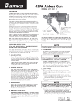
43P Airless Gun
MODEL: 6370-0000-6
NOZZLE
SOLVENT
PURGE
SAFETY
LOCK
The Binks Model 43P is a low to medium-volume plural
component (spray and/or pour) dispensing device designed
specifically for plural component systems. Capacity is up
to 20 lbs. spray using a patented static mixing principle.
The 43P, and its companion the 43PA (automatic), uses
the opposed internal orifices principle with no moving
parts (patented).
Spray patterns are by nozzle selection.
Gun output is dependent upon nozzle and impingement
orifices in conjunction with applied fluid pressures.
Impingement orifices usually are matched but may be
dissimilar to “balance” divergent viscosities and/or ratios.
The 18-8 stainless steel head is designed with cross-
drilled ports for ease of maintenance. The ports allow
access to remove impacted cured resins. Immersion in
solvent will not affect the PTFE seals.
Both resin (1/4 NPS) ports have check valves. The needle
valves share common parts (springs, housing, take-up nuts,
packings and followers) for simplicity. The resin needles
are ball type, the purge is tapered tip.
The rugged forged aluminum gun handle is anodized for
corrosion resistance. The trigger’s finger geometry affords
comfortable trigger pull and operation.
DESCRIPTION

2
Warning
!
In this part sheet, the words WARNING, CAUTION and NOTE are used to emphasize important safety information as follows:
CAUTION
Hazards or unsafe practices which could
result in minor personal injury, product
or property damage.
!
WARNING
Hazards or unsafe practices which could
result in severe personal injury, death or
substantial property damage.
!
NOTE
Important installation, operation or
maintenance information.
Read the following warnings before using this equipment.
READ THE MANUAL
Before operating finishing equipment, read and
understand all safety, operation and maintenance
information provided in the operation manual.
PRESSURE RELIEF PROCEDURE
Always follow the pressure relief procedure in the
equipment instruction manual.
MEDICAL ALERT
Any injury caused by high pressure liquid can be
serious. If you are injured or even suspect an injury:
a) Go to an emergency room immediately.
b) Tell the doctor you suspect an injection injury.
c) Show the doctor this medical information or
the medical alert card provided with your
airless spray equipment.
d) Tell the doctor what kind of fluid you were
spraying or dispensing.
e) Refer to the Material Safety Data Sheet for
specific information.
TOXIC FLUID & FUMES
Hazardous fluid or toxic fumes can cause serious
injury or death if splashed in the eyes or on the skin,
inhaled, injected or swallowed. LEARN and KNOW
the specific hazards or the fluids you are using.
WEAR RESPIRATOR
Toxic fumes can cause serious injury or death if
inhaled. Wear a respirator as recommended by
the fluid and solvent manufacturer’s Material
Safety Data Sheet.
ELECTRIC SHOCK / GROUNDING
Improper grounding or sparks can cause a
hazardous condition and result in fire, explosion
or electric shock and other serious injury.
PROJECTILE HAZARD
You may be injured by venting liquids or gases
that are released under pressure, or flying debris.
FIRE AND EXPLOSION HAZARD
Improper equipment grounding, poor ventilation,
open flame or sparks can cause hazardous
conditions and result in fire or explosion and
serious injury.
STATIC CHARGE
Fluid may develop a static charge that must be
dissipated through proper grounding of the
equipment, objects to be sprayed and all other
electrically conductive objects in the dispensing
area. Improper grounding or sparks can cause a
hazardous condition and result in fire, explosion
or electric shock and other serious injury.
WEAR SAFETY GLASSES
Failure to wear safety glasses with side shields
could result in serious eye injury or blindness.
OPERATOR TRAINING
All personnel must be trained before operating
finishing equipment.
EQUIPMENT MISUSE HAZARD
Equipment misuse can cause the equip ment to
rupture, malfunction, or start unexpectedly and
result in serious injury.
KEEP EQUIPMENT GUARDS IN PLACE
Do not operate the equipment if the safety
devices have been removed.
HIGH PRESSURE CONSIDERATION
High pressure can cause serious injury. Relieve all
pressure before servicing. Spray from the spray
gun, hose leaks, or ruptured components can
inject fluid into your body and cause extremely
serious injury.
GET IMMEDIATE MEDICAL ATTENTION
To prevent contact with the fluid, please note the
following:
a) Never point the gun/valve at anyone or any
part of the body.
b) Never put hand or fingers over the spray tip.
c) Never attempt to stop or deflect fluid leaks
with your hand, body, glove or rag.
d) Always have the tip guard on the spray gun
before spraying.
e) Always ensure that the gun trigger safety
operates before spraying.
f) Always lock the gun trigger safety when you
stop spraying.
DE-ENERGIZE, DEPRESSURIZE, DISCONNECT
AND LOCK OUT ALL POWER SOURCES DURING
MAINTENANCE
Failure to De-energize, disconnect and lock out
all power supplies before performing equipment
maintenance could cause serious injury or death.
FOR FURTHER SAFETY INFORMATION REGARDING BINKS AND DEVILBISS EQUIPMENT,
SEE THE GENERAL EQUIPMENT SAFETY BOOKLET (77-5300).
IT IS THE RESPONSIBILITY OF THE EMPLOYER TO PROVIDE THIS INFORMATION TO THE OPERATOR OF THE EQUIPMENT.
CA PROP
65
PROP 65 WARNING
WARNING: This product contains chemicals known
to the State of California to cause cancer and
birth defects or other reproductive harm.

Binks MODEL 102-1700 (43P) AIRLESS SPRAY GUN
3
Your Binks 43P Airless Spray Gun has been thoroughly
tested before leaving the factory. No adjustment is
required prior to its operation other than installing the
nozzle tip.
1. Solvent Hook-up
Hook up solvent line and check to insure proper purg-
ing. Open purge valve and allow solvent to enter the
gun head. Activate valve on-off and observe solvent
spray emitting from front of gun. It is important that
solvent purge be available in case of incorrect resin-
hardener hook-up, reacting fluids, or mixed resins
remaining in gun mix chamber.
2. Gun Hook-up
Remove Items 1, 2, 3, and 5. Connect material lines to
gun. Run system to insure material flows through gun.
Shut gun off and allow system to run to stall. Check
for leaks at all connections.
3. Material Flow Check
Aim gun into a suitable waste container or place
waste container under front of gun head. Operate for-
mulator and open gun needles until both fluids flow
freely from front of gun head. 1:1 systems should
appear equal in volume. (Off-ratio systems will visibly
be unequal.)
4. Calibration
To check for correct proportioning of two fluids the
simplest method is to take two containers of equal
capacity and fill them simultaneously.
Deviation from volumetric ratio of 1:1 can be attributed
to malfunctioning pump(s) or to excessive differences in
viscosity of components.
5. Shut-Down
When spraying is discontinued for extended periods
of time such as lunch, overnight or weekends, the fol-
lowing procedures are recommended:
A. Remove items 1, 2, 3, and 4 and place in clean sol-
vent. Pack mixing chamber with petroleum jelly.
B. Leave gun connected to the hoses and formulator
and shut-off fluid supply to the gun, but do not
bleed the pressure.
For long shut-down periods, it is necessary to
purge (“flush”) the system completely (use solvent
recommended by the material supplier). Pump sol-
vent through system until all traces of material are
removed. Pack gun mixing chamber with petro-
leum jelly. To exclude ambient moisture and/or for-
eign matter from hoses and formulator, fill system
with an inert fluid such as a plasticiser (DOTP,
etc.).
6. Gun Ports
The gun head is drilled with bottom material iInlet
ports (1/4 NPT) and solvent port (1/8 NPT).
7. Priming and “Warm-Up”
Heating resins (at the gun head) at start-up can help
assure improved mixing. “Warm-up” may also be
needed after a down-time of duration that would allow
heat loss in hoses to gun.
NOTE
Purge gun with solvent at end of material flow check.
NOTE
When a heated system is used, be sure materials are pre-
heated approximately 1 hour prior to calibrating.
NOTE
If you wish to disconnect fluid hoses, you must first shut
off main air supply to formulator and gun and then bleed
off all fluid material pressure before removing any hoses.
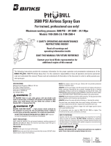
NOZZLE
NUT
SEAL
SLEEVE
GUN HEAD
IMPINGEMENT
ORIFICES
SEAT (SOLVENT)
FOLLOWER
PACKING
(SOLVENT)
PACKING NUT
YOKE
PLUNGER
HOUSING
BUSHING
STEM ASSEMBLY
(PURGE)
PURGE KNOB
RESIN
SEAT
RESIN TIP
SEAL
PACKING
HOUSING
SPRING
TAKE-UP
NUT
RESIN
NEEDLE
SPOOL
NUT
LOCK NUT
HANDLE
(BODY)
PLUG/RATIO
CHECK PORT

4
Binks MODEL 102-1700 (43P) AIRLESS SPRAY GUN
ITEM PART
NO. NO. DESCRIPTION QTY.
1 102-3327 NUT .......................... 1
2 ♦ NOZZLE TIP .................... 1
3 54-1439
■
GASKET ....................... 1
4 102-1738
■
INSERT (PTFE) ................... 2
5 102-1716 PLUG ......................... 2
6 102-1720*
■
ORIFICE .035" Dia. ............... 2
7 20-2195-1 SCREW 1/4-20 x 3/4" Long .......... 1
8 102-1761 HEAD ......................... 1
9 102-1765
■
SEAT .......................... 2
10 102-1708
■
SEAT .......................... 1
11 102-1717
■
FOLLOWER .................... 1
12 2-28
■
PACKING ...................... 1
13 54-1969 NUT .......................... 1
15 20-1576 ALLEN WRENCH (Not Shown) ...... 1
17 OMX-88 BRUSH (Not Shown) .............. 1
18 82-469 BRUSH (Not Shown) .............. 1
20 102-1780
■
CHECK VALVE ASSEMBLY. ........ 2
21 102-1743 SOLVENT TUBE ................. 1
22 72-727
ADAPTER 1/4 NPS(m) x 1/8 NPT(f)
........ 1
23 82-126 SCREW ........................ 1
24 102-1702 BODY ......................... 1
25 54-1020 TRIGGER STUD ................. 1
26 54-1641 LOCK ......................... 1
ITEM PART
NO. NO. DESCRIPTION QTY.
27 54-1637 SPRING ........................ 1
28 54-1635 SCREW ........................ 1
29 102-1705 HOUSING ...................... 1
30 102-1703 KNOB ......................... 1
31 102-1719 STEM ......................... 1
32 102-1704 BUSHING ...................... 1
33 102-3335
■
GASKET ....................... 2
34 102-1749 PLUNGER ...................... 1
35 52-487 NUT .......................... 2
36 102-2066 YOKE ......................... 1
37 102-2067 BLOCK ........................ 1
38 102-2069 STOP ......................... 1
39 20-3553 BALL ......................... 1
40 84-353 SPRING ........................ 1
41 102-2065
SAFETY LOCK YOKE ASSEMBLY.
..... 1
42 102-1709 TRIGGER ...................... 1
44 102-1757
■
VALVE ASSEMBLY ............... 2
45 102-1756 PACKING. ...................... 2
46 102-1725 RETAINER ..................... 2
47 102-1730
■
SPRING ........................ 2
48 102-1726 GLAND ........................ 2
49 54-1663 NUT .......................... 2
50 102-1759 NEEDLE ASSEMBLY .............. 2
PARTS LIST
(When ordering, please specify Part No.)
♦ Not part of gun assembly. Order separately.
■ Recommended as replacement items, also available in 106-1078
Spare Parts Kit.
*
Larger or smaller orifices available for special applications.
106-1078 SPARE PARTS KIT INCLUDES
ITEM 3 4 6 9 10 11 12 20 33 44 47
QTY. 2 2 2 2 1 1 1 2 2 2 2
1
2
3
4
5
5
6
6
7
8
9
9
10
11
12
13
21
22
23
24
25 26
27
28
29
30
31
32
33
34
35
36
37
38
39
40
41
42
44
45
46
47
48
49
50
20
33
Item 38
Safety “ON”
Position
Flat
Faces
Downward
Safety “OFF”
Position
Flat
Faces
Upward

MAINTENANCE INSTRUCTIONS
5
A. Short Period Shut-down.
1. When stopping operation of the Model 43P gun for short
periods exceeding 1/2 hour, remove nut (1), nozzle tip (2),
gasket (3), and any washers from gun, and soak them in a
clean solvent.
2. Inspect inside of mix chamber (8) and clean thoroughly.
3. Prior to reassembly, blow tip and washers with compressed
air and inspect for cleanliness.
B. Long Period Shut-down.
1. For overnight or longer periods of down-time, it is recom-
mended that items 1, 2, 3, (two) plugs (5) and (two) orifices
(6) be removed and placed in a clean solvent.
2. Hold gun over empty container. Rotate knob (30) counter-
clockwise to obtain solvent flow to back-flush the mixing
chamber in head (8). After flushing, inspect chamber to be
sure it is clean.
3. After mixing chamber is clean, pack over openings on head
(8) with Vaseline
®
to prevent crystallization of materials in
head.
C. Needle Valve Assembly, (two) (50).
1. If fluid leaks through gland (48), tighten only enough to
stop leak.
2. If leak cannot be stopped:
a. Shut off pump and relieve pressure within entire system.
b. Remove screw (23), stud (25), and trigger (42).
c. Use Allen wrench and remove screw (7). Separate head
(8) and body (24).
d. Lift off safety lock yoke assembly (41). Use crescent or
open-end wrench and remove needle assembly (50).
e. Turn out gland (48) until no threads are engaged, thus
relieving spring tension on packing (45).
f. Remove each of the two retainers (46).
g. With knife edge, or sharp tool, pick up split in packing
(45) and remove.
h. Slip new packing (45) (factory pre-split) over needle
wire in needle and packing assembly (43), again exercis-
ing care not to damage wire.
i. Tighten gland (48) into retainer (46).
j. Wrap retainer (46) threads with PTFE tape and insert
into head (8). Reinstall needle assembly (50) by revers-
ing above procedures (a) to (c) in Step C.2.
3. The seat (9) is designed for long life and is not usually
removed for normal maintenance. If it is damaged and must
be removed, repeat procedures (a) to (c), Step C.2. then:
a. Remove plug (5).
b. Insert 3/16" dia. brass rod, or drift pin, through plug (5)
hole and knock out seat (9).
c. To replace, insert new seat (9) in the opposite direction
from which it was removed. Press and tap into place.
D. Fluid Inlet Fittings, (two) Items 20.
1. Be sure check valve assembly (20) is clean and moving
freely before connecting hoses.
2. When replacing or reinserting (two) check valve assemblies
(20), always wrap threads with PTFE tape.
E. Solvent Flush Valve.
1. Turn off pump and release pressure.
2. To replace packing (12) or seat (10):
a. Remove stem (31) by turning out knob (30).
b. Remove nut (13).
c. Going through front of mix chamber, head (8), use 3/16"
dia. brass rod or drift pin to push out packing (12).
d. Replace by reversing above procedure.
3. a. High Fluid Pressures—Be sure the main air or electric
supply to outfit is turned “OFF” and liquid pressures
relieved from hoses and gun by pulling trigger BEFORE
ANY disassembly.
b. Small Orifices—Any dirt in the fluid, or lack of proper
maintenance, will cause constant orifice plugging.
ACCESSORIES
MODEL 102-2160 FILTER (100 mesh, in-line)
MODEL 102-2176 FILTER (200 mesh)
PARTS LIST
(When ordering, please specify Part No.)
ITEM PART
NO. NO. DESCRIPTION QTY.
1 102-2159 SUMP ....................................................... 1
2 102-2161 ELEMENT (100 mesh) .............................. 1
3 102-2177 ELEMENT (200 mesh) .............................. 1
4 102-2158 STEM ASSEMBLY ..................................... 1
NOTE
Never open knob (30) when trigger is pulled. CAUTION:
YOU ARE WORKING WITH TWO HAZARDOUS FACTORS:
1
2 3
4
1/4" NPS(f) (SS)
1/4" NPS(m)

6
NOTES

NOTES
7

5/12 ©2012 Binks All rights reserved. Printed in U.S.A.
U.S.A./Canada Customer Service
195 Internationale Blvd.
Glendale Heights, IL 60139
630-237-5000
Toll Free Customer Service
and Technical Support
800-992-4657
Toll Free Fax
888-246-5732
Binks Sales and Service: www.binks.com
WARRANTY
This product is covered by Binks’ 1 Year Limited Warranty.
77-1722R-12 Revisions: PTFE reference update
throughout; (P1) Corrected model number;
(P2) Added Prop 65 warning; (P8) Updated
contact information.
/