Page is loading ...

KING CANADA
INSTRUCTION MANUAL
COPYRIGHT © 2008 ALL RIGHTS RESERVED BY KING CANADA TOOLS INC.
MODEL: 8560LST
WET•DRY VACUUM

WARRANTY INFORMATION &
SAFETY RULES FOR WET•DRY VACUUMS
2-YEAR
L
IMITED WARRANTY
FOR THIS WET•DRY VACUUM
KING CANADA TOOLS
OFFERS A 2-YEAR LIMITED WARRANTY
FOR NON-COMMERCIAL USE.
PROOF OF PURCHASE
P
lease keep your dated proof of purchase for warranty and servicing purposes.
REPLACEMENT PARTS
Replacement parts for this product are available at our authorized King Canada service centers across Canada.
LIMITED TOOL WARRANTY
King Canada makes every effort to ensure that this product meets high quality and durability standards. King Canada warrants to the original
retail consumer a 2-year limited warranty as of the date the product was purchased at retail and that each product is free from defects in
materials. Warranty does not apply to defects due directly or indirectly to misuse, abuse, normal wear and tear, negligence or accidents, repairs
done by an unauthorized service center, alterations and lack of maintenance. King Canada shall in no event be liable for death, injuries to
persons or property or for incidental, special or consequential damages arising from the use of our products.
To take advantage of this limited warranty, return the product at your expense together with your dated proof of purshase to an authorized King
Canada service center. Contact your retailer or visit our web site at www.kingcanada.com for an updated listing of our authorized service
centers. In cooperation with our authorized serviced center, King Canada will either repair or replace the product if any part or parts covered under
this warranty which examination proves to be defective in workmanship or material during the warranty period.
ITEMS NOT COVERED UNDER WARRANTY
Accessories supplied with this vacuum such as the hose, 14” floor sweep, crevice tool, gulper tool, cartridge filter and foam filter are not covered
under warranty and are available as optional accessories at your nearest King Canada distributor.
VOLTAGE WARNING: Before connecting this vacuum to a power source (receptacle, outlet, etc.) be sure the voltage supplied is the same
as that specified on the nameplate. A power source with voltage greater than the specified voltage on nameplate can result in SERIOUS
INJURY to the user - as well as damage to the motor. If in doubt DO NOT PLUG IN THE VACUUM. Using a power source with voltage
less than the nameplate is also harmful to the motor.
1. KNOW YOUR VACUUM. Read and understand the instruction
manual and labels af
fixed to the vacuum. Learn its application
and limitations as well as its specific potential hazards.
2.
WEAR PROPER APPAREL.
Do not wear loose clothing, gloves,
neckties or jewelry (rings, watch) because suction force could
get them caught in the vacuum. Wear protective hair covering to
contain long hair. Roll up long sleeves above the elbows.
3. Do NOT expose to rain, this vacuum must be stored indoors.
4. Do not handle the electrical plug or vacuum with wet hands.
5. Never use this vacuum with any opening blocked, keep
opening free of dust, hair
, lint or anything that will restrict air flow
.
6. Never vacuum anything that is on fire, burning or smoking
such as matches, cigarettes or hot ashes. Never vacuum
flammable or combustible liquids such as gasoline, electrical
devices could produce sparks which can cause a fire or
explosion! Never vacuum toxic or hazardous materials.
7. Never use this vacuum without filters installed.
8. Never vacuum coal ash, cement or drywall dust without
adaquate filtration in place or you could damage the motor or the
material could be exhausted back into the air. When vacuuming
drywall dust, a high ef
ficiency drywall filter must be used to
prevent serious motor damage. These high efficiency
accessories are available and are listed in this manual.
IMPORTANT SAFETY RULES FOR WET•DRY VACUUMS

GETTING TO KNOW YOUR VACUUM,
ELECTRICAL INFO & SPECIFICATIONS
SPECIFICATIONS
Model............................................................................
8560LST
Voltage................................................................................
1
10V
Horsepower ........................................................
6.5 HP
(peak)
Amperage..........................................................................
10.5A
Phase ........................................................................................1
Hertz ..................................................................................
60Hz
Tank size ..............................................
16 Gallon (US)/60 liters
Air flow ........................................................................
229 CFM
ELECTRICAL INFO
POWER SUPPLY- WARNING: YOUR VACUUM MUST BE
CONNECTED TO A 110V, MINIMUM 15-AMP. BRANCH CIRCUIT.
FAILURE TO CONNECT IN THIS WAY CAN RESULT IN INJURY
FROM SHOCK OR FIRE.
DOUBLE INSULATED-GROUNDING NOT REQUIRED, WHEN
SERVICING USE ONLY IDENTICAL REPLACEMENT PARTS.
POLARIZED PLUG
- Double insulated tools are equipped with a
polarized plug (one blade is wider than the other), refer to Fig.1. This
plug will fit in a polarized outlet only one way. If the plug does not fit fully
into the outlet, reverse the plug. If it still does not fit, contact a qualified
electrician to install a proper outlet. Do not alter or change the plug in
any way. Double insulation eliminates the need for three wire grounded
power cords and grounded power supply system.
110V OPERATION- As received from the factory, your vacuum is ready
to run for 1
10V operation.
This vacuum is intended for use on a circuit
that has an outlet and a plug which looks like the one illustrated in Fig.1.
EXTENSION CORDS- The use of any extension cord will cause some
loss of power. Use the table in Fig.2 to determine the minimum wire size
(A.W.G-American Wire Gauge) extension cord needed. For circuits that
are further away from the electrical circuit box, the wire size must be
increased proportionately in order to deliver ample voltage to the motor
.
Refer to Fig.2 for wire length and size.
FIGURE 1
LENGTH OF
CONDUCTOR
0-25 FEET
26-50 FEET
51-100 FEET
WIRE SIZES REQUIRED
(AMERICAN WIRE GAUGE)
1
10V LINES
NO.16
NO.16
NO.14
FIGURE 2
POLARIZED OUTLET
POLARIZED
PLUG
1) Switch
2
) 2-1/2” flex hose
3) Contour handle with air control
4) Transportation handle with soft-grip
5) Power cord/cord wrap (1 of 2)
6) Accessory storage bag
7) Cover/motor latch (1 of 2)
8
) 2pc. 2-1/2” extension wands
9) Stainless steel tank
10) On-board accessory storage tray
11) 14” floor sweep with squeegee insert
12) Locking caster wheel
13) Cartridge filter
14) Crevice tool
15) Gulper tool
16) Foam filter
17) Tank drain cap
18) Blower outlet/noise diffuser
GETTING TO KNOW YOUR VACUUM

UNPACKING & ASSEMBLING
YOUR VACUUM
ATTENTION! The vacuum accessories are packed inside
t
he vacuum tank.
UNPACKING YOUR VACUUM
Remove the entire contents of the carton
, please note that most of
the accessories are packed inside the vacuum tank. To access these
accessories, push the cover latches (step 1) Fig.3 inward, lift the tank
cover/motor assembly (step 2) and then remove the accessories inside
the tank.
WARNING! DO NOT CONNECT THE POWER CORD TO THE POWER SOURCE UNTIL THE
FOLLOWING ASSEMBLY AND SET-UP INSTRUCTIONS HAVE BEEN DONE.
ASSEMBLING LARGE WHEELS AND CASTER WHEELS
Two large 8” wheels and two caster wheels are included and should be assembled to the
bottom of the base.
1) With the tank cover/motor assembly removed, turn the tank upside down. Insert the caster
wheels into the two openings in the base and apply pressure until casters snap into place.
2) To assemble the large wheels to the base, first insert the wheel shaft (A) Fig.4 into the rear
support block, slide a washer (B) on the shaft, then slide wheel (C) on the shaft, then
another washer (B). Insert cotter pin (D) into the hole at the end of the shaft to lock wheel.
Snap the wheel hub (E) onto the wheel. Repeat these steps to install the other wheel.
TRANSPORT HANDLE ASSEMBLY
A transport handle is included and should be assembled to the mounting brackets on the sides
of the stainless steel tank assembly.
1) Insert both ends of the transport handle into the mounting brackets on the sides of the
stainless steel tank, push down until each lock pin clicks in place. See Fig.5.
NOISE DIFFUSER ASSEMBLY
For quiet operation, a noise diffuser is included and should be installed to the rear blower outlet.
1) Install the noise diffuser (A) Fig.6 into the blower outlet (B) by inserting the locking end and
turning clockwise to lock it in place.
ACCESSORY STORAGE BAG ASSEMBLY
An accessory storage bag is included and should be installed to the transport handle.
1) Install the storage bag to the transport handle using the retaining clips as shown in Fig.7.
HOSE, WANDS AND ACCESSORY ASSEMBLY
1) Install the locking end of the flex hose Fig.8 to the vacuum inlet (front of the vacuum) by
inserting the locking end and turning clockwise to lock it in place.
2) Assemble the 2 extension wands and the contour handle with air
control together and then attach the flex hose to the contour handle.
3) Attach either the floor sweep Fig.8, crevice tool or gulper tool to the
other end of the extension wand assembly
.
Figure 4
Figure 5
Figure 6
Figure 7
Figure 3
Figure 8

OPERATION
INSTALLING THE CORRECT FILTER FOR THE APPLICATION
Before reinstalling the cover/motor assembly on, it is important to determine the desired
c
leaning application, wet or dry vacuuming. Each cleaning application requires different types of
f
ilters.
D
RY VACUUMING OPERATIONAL STEPS
Before vacuuming dry materials, it is important that you have read and understood the
safety rules in this manual.
1) Unplug the power cord from the power source.
2) Remove the cover/motor assembly, for normal vacuuming operation, a clean and dry foam
filter should be installed. If the vacuuming operation is extremely dusty, a clean and dry
cartridge filter should be installed instead. Slide the foam filter (A) Fig.9 or the cartridge
filter (B) over the cage (C). If it is necessary to vacuum dry materials and you have just
finished vacuuming wet materials, the foam or cartridge filter must be completely dried or else
they will clog up quickly and will be difficult to clean. The foam or cartridge filter can be dried
quickly by running the vacuum for 5-10 minutes without the hose installed.
3) Reposition and secure the cover/motor assembly to the tank.
4) Attach the flex hose to the inlet on the front of the vacuum.
5) Assemble the 2 extension wands and the contour handle together and then attach hose to
contour handle.
6) Attach either the floor sweep, crevice tool or gulper tool to the other end of the extension
wand.
7) Plug the power cord to a 110V power source.
8) Start the vacuum by pushing the On/Off switch to the On position as shown in Fig.10. The On
position is indicated by the international symbol “I” on the switch.
9) Once the vacuuming operation is finished, push the switch to the Off position indicated by the
international symbol “O” on the switch and unplug the power cord from the power source.
10) Remove the cover/motor assembly and lay it aside, being careful not to damage the filter
and dump the tank contents into a suitable waste disposal container.
Airborn dust will be
produced when cleaning, wear dust mask!
Warning!
Never use the cartridge filter for vacuuming wet materials. When vacuuming fine dust, it will be
necessary to clean the foam and cartridge filters at more frequent intervals.
WET VACUUMING OPERATIONAL STEPS
Before vacuuming wet materials, it is important that you have read and understood the
safety rules in this manual.
1) Unplug the power cord from the power source.
2) Remove the cover/motor assembly and install a clean and dry foam filter
. If wet vacuuming
under normal conditions or when vacuuming large amounts of liquid, only install the foam filter,
slide the foam filter (A) Fig.1
1 over the cage (B). Make sure the inside of the tank is clean.
3) Reposition and secure the cover/motor assembly.
4) Attach the flex hose to the inlet on the front of the vacuum.
5)
Assemble the 2 extension wands and the contour handle together and then attach hose to
contour handle.
6) Attach either the floor sweep, crevice tool or gulper tool to the other end of the extension
wand. For wet applications, remove the brush insert from the floor sweep by pressing the 2
snap points at each end of the floor sweep, the assembly will pop out, replace it with the
squeegee insert and snap it back into the floor sweep.
7) Plug the power cord to a power source.
8) Start the vacuum by pushing the On/Off switch to the On position as shown in Fig.12. The On
position is indicated by the international symbol “I” on the switch.
9) When vacuuming large amounts of liquid, do not completely immerse the nozzle accessory
in the liquid, leave a gap at the top of the nozzle accessory opening to allow air inflow.
10) Once the vacuuming operation is finished, push the switch to the Of
f position indicated by
the international symbol “O” on the switch and unplug the power cord from the power source.
Warning!
Never use the cartridge filter for vacuuming wet materials.
The foam filter should be cleaned after each wet vacuuming operation.
Should it become necessary to pick up the vacuum to move it, DO NOT pick up the vacuum by
the top handle unless the tank is empty. Do not pull the vacuum by the hose, this may tip the
vacuum over if the wheels are obstructed in any way
.
Figure 9
Figure 10
Figure 11
Figure 12

OPERATION & MAINTENANCE
AUTOMATIC SUCTION SHUT-OFF AND EMPTYING LIQUID FROM TANK
This section relates to wet vacuuming operations. This vacuum is fitted with an automatic
suction shut-off float cup (A) Fig.13 which floats up when the liquid level increases in the tank,
it then stops the suction action when the tank has reached its maximum capacity of liquid. Make
sure the float cup is clean at all times.
T
he user will notice an increased motor speed, when this happens;
1
) Turn off the vacuum immediately and unplug the power cord from the power source.
2) Remove the cover/motor assembly and lay it aside, being careful not to damage the filter and
empty the tank contents into a suitable waste disposal container by removing the drain cap
(A) Fig.14 found on the lower left side of the tank.
3) The inside of the tank should be cleaned, also check the foam filter and clean it from the
inside out if necessary.
4) To continue vacuuming wet materials, reposition and secure the cover/motor assembly, plug
the power cord to a power source and proceed.
BLOWER FEATURE
This vacuum can be used as a powerful blower. To use the blower feature, remove the noise
diffuser (A) Fig.15 from the blower outlet (B). Disconnect the flex hose from the front of the
vacuum and reconnect it to the blower outlet. Turn the vacuum On, your vacuum is now a
blower to clear work tables of debris, blow leaves etc...
STANDARD AND OPTIONAL ACCESSORIES
The following chart lists the standard accessories included and the available optional
accessories for this wet•dry vacuum. Please note that these accessories are not covered under
warranty and are available at your nearest King Canada distributor.
ON-BOARD ACCESSORY STORAGE
When the 14” floor sweep, crevice tool or gulper tool are not in use, they can be stored in the
on-board storage on the top of the motor cover or the accessory storage bag as shown in Fig.16.
MAINTAINING YOUR VACUUM AND ACCESSORIES
Warning! To reduce the risk of injury and electrical shock, unplug the power cord from
the power source. Airborn dust will be produced when cleaning, wear dust mask!
T
o maintain peak vacuum performance, the cartridge and foam filters must be cleaned often.
When not in use, wrap the power cord around the power cord posts as shown in Fig.17.
Filter maintenance- Clean the foam filter by washing it inside out in a mild soapy water and then
rince with clean water. Clean the cartridge filter in a mild soapy water and then rince with clean
water. Allow these filters to dry completely before using.
General Maintenance and Inspection- The inside of the tank, hose, extension wands and
accessories should be cleaned after every use, this cleaning should only be done outdoors with
the power cord disconnected from the power source. Check the condition of the power cord and
make sure it is not damaged. Also check the condition of the filters for tears and small holes. Do
not use filters with tears or small holes, replace with new filters.
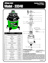
PARTS DIAGRAM & PARTS LISTS
Refer to the Parts section of the King Canada web site for the most updated parts diagram and
parts list.
Model
KVAC-1040
KVAC-1075
KVAC-1104
KVAC-1106
KVAC-1108
KVAC-1115
KVAC-1123
KVAC-1140
Description
Foam Filter- 1pc.
Cartridge Filter- 1pc.
2-1/2” Gulper Tool- 1pc.
2-1/2” Crevice Tool- 1pc.
14” x 2-1/2” Floop Sweep- 1pc.
2pc. Extension wands
Caster Wheels- 2pc. kit
High Efficiency Cartridge Filter
Included/Optional
1pc. Included
1pc. Included
1pc. Included
1pc. Included
1pc. Included
2pc. Included
2pc. Included
Optional
Usage
Wet•Dry Vacuuming Applications
Dry Vacuuming Applications
General purpose
Upholstery and car interiors
General purpose-squeegee attachment
Replacement kit
Replacement kit
Drywall and fine dust applications
Figure 13
Figure 14
Figure 15
Figure 16
Figure 17
/