Audio Technica PRO 227 Operating instructions
- Category
- Guitar accessories
- Type
- Operating instructions
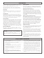
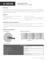
Audio Technica PRO 227 is a professional wireless system comprising a receiver and a transmitter, offering exceptional sound quality and reliable performance for various applications. With its true diversity reception and two independent RF sections, it minimizes interference and dropouts, ensuring clear and consistent audio transmission. The system's versatile UniPak body-pack transmitter allows for connecting dynamic and electret condenser microphones or Hi-Z instrument pickups, making it suitable for a wide range of uses.
Audio Technica PRO 227 is a professional wireless system comprising a receiver and a transmitter, offering exceptional sound quality and reliable performance for various applications. With its true diversity reception and two independent RF sections, it minimizes interference and dropouts, ensuring clear and consistent audio transmission. The system's versatile UniPak body-pack transmitter allows for connecting dynamic and electret condenser microphones or Hi-Z instrument pickups, making it suitable for a wide range of uses.


-
 1
1
-
 2
2
-
 3
3
-
 4
4
-
 5
5
-
 6
6
-
 7
7
-
 8
8


Audio Technica PRO 227 Operating instructions
- Category
- Guitar accessories
- Type
- Operating instructions
Audio Technica PRO 227 is a professional wireless system comprising a receiver and a transmitter, offering exceptional sound quality and reliable performance for various applications. With its true diversity reception and two independent RF sections, it minimizes interference and dropouts, ensuring clear and consistent audio transmission. The system's versatile UniPak body-pack transmitter allows for connecting dynamic and electret condenser microphones or Hi-Z instrument pickups, making it suitable for a wide range of uses.
Ask a question and I''ll find the answer in the document
Finding information in a document is now easier with AI
Related papers
-
Audio Technica ATW-1951 Operating instructions
-
-
-
Audio Technica ATW-7375 Operating instructions
-
AmpliVox ATW-701L User manual
-
-
-
Audio-Technica ATW-1663 User manual
-
-
Audio Technica System 8 Operating instructions
Other documents
-
-
 Califone R-2000 User manual
-
 Sense SE-300-HM-SW Quick start guide
-
 W Audio TP-500 User manual
-
 W Audio TP-500 User manual
-
 W Audio TP-500 User manual
-
-
TOA WT-5810 User manual
-
-


