Kenwood KAC-816 User manual
- Category
- Car audio amplifiers
- Type
- User manual

KAC-816
MONO POWER AMPLIFIER
INSTRUCTION MANUAL
© PRINTED IN MEXICO B64-1170-00 (EM)

2
Safety precautions
Take the following precautions to
prevent fire and avoid personal
injury :
•When extending the battery cable, or
ground cable, use 5mm
2
(AWG10) or
larger automotive grade cable to avoid
cable deterioration or damage to the
covering.
•Check that no metal objects (coins, tools,
etc.) are left inside the unit to avoid short
circuits.
•If you smell or see smoke, turn the
power off immediately and consult your
Kenwood dealer.
•Do not touch the unit during use because
the surface of the unit becomes hot and
may cause burns if touched.
Take the following precautions to
keep the unit in proper working
order.
•Be sure the unit is connected to a 12V
DC power supply with a negative ground
connection.
•Do not open the top or bottom cover.
•Do not install the unit in places it is
exposed to direct sunlight, high heat or
humidity, water may splash over it, or
dust exists.
If you have difficulty in installing this unit
in your vehicle, contact your Kenwood
dealer.
Cleaning the unit
If the surface is dirty, wipe it clean with a
silicon cloth or soft dry cloth with the
power off.
Do not use hard cloths or paint thinner,
alcohol, or other volatile solvents. These
may damage external surfaces or remove
indicator characters.
2CAUTION
NOTE
2CAUTION
2WARNING
Accessories
Part name
Number
of Items
External
View
Battery cable
(Yellow) (6 m)
1
Ground cable (Black)
(1 m)
1
Self-tapping screws
(ø4 × 16 mm)
4
Terminal cover
(Power terminal)
1
Part name
Number
of Items
External
View
Round terminal
(Large)
1
Round terminal
(Medium)
2
Round terminal
(Small)
1
Grommets 1

3
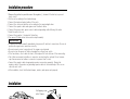
Installation procedure
Installation
• Since the power amplifier has no parts which require operation, it can be installed at a position
away from the driver’s seat without any hindrances.
As generally accepted positions for its installation, places such as inside the trunk, etc. can be
considered.
• Use the extension cables. (Optional)
• Do not install the unit under the carpet. Otherwise heat build-up occurs and the unit may be
damaged.
• Install this unit in a location which allows heat to easily dissipate.
Once installed, do not place any object on top of the unit.
• Install the unit securely in a location that does not interfere with driving.
2CAUTION
Installation board, etc.
(thickness : 15 mm or more)
Self-tapping screw
(ø4 × 16 mm)
CA-2SL CA-12SL CA-22SL CA-52SLRCA cable
CA-3WL CA-13WL CA-23WL CA-53WLRCA cable (ø7mm)
CA-5W CA-15W CA-25W CA-45W CA-65WRCA cable (ø12mm)
0.5m 1m 2m 4m 5m 6m
Type
Length
1. Remove the ignition key and disconnect the negative - terminal of the battery to prevent
short circuits.
2. Set the unit according to the intended usage.
3. Connect the input and output cables of the units.
4. Connect the center unit and this unit according to the required application.
5. Connect the speaker cables and sigma servo feed back cables.
6. Connect the power cable, power control cable and grounding cable following this order.
7. Install the unit in the car.
8. Connect the negative - terminal of the battery.
9. Turn power ON and ensure that sound is output normally.
• If sound is not output normally, immediately turn power off and check connections. Be sure to
perform the sigma servo connection correctly.
• Be sure to make correct connections of the sigma servo terminals.
• Be sure to turn the power off before changing the setting of any switch.
• If the fuse blows, check cables for shorts, then replace the fuse with one of the same rating.
• Check that no unconnected cables or connectors are touching the car body. Do not remove
caps from unconnected cables or connectors to prevent short circuits.
• Connect the speaker cables to appropriate speaker connectors separately. Sharing the
negative cable of the speaker or grounding speaker cables to the metal body of the car can
cause this unit to fail.
• After installation, check that the brake lamps, winkers, and wipers work properly.
2CAUTION

4
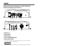
Controls
Operations of the following control and switches are required in accordance with
the center unit and speakers connected with this unit.
POWER IN
FUSE(20A)
BATT
GND
FUSE(20A)
P.CON(REMOTE)
SPEAKER OUTPUT
1 2 3
456
MONO
POWER AMPLIFIER
L
25Hz
15Hz
INFRASONIC
OFF
INPUT
SENSITIVITY(V)
LPF
FREQUENCY(Hz)
GND
R
LINE IN
0.3
0.5
1
2
3
4
50.2
150
100
70
50 200
LEFT RIGHT
SPEAKER LEVEL INPUT
@7 8 9 0 !
20
20
SERVO ΙΙ
∑
SERVO ΙΙ
∑
1
FUSE (20 A
×
2)
2
Battery terminal
3
Ground terminal
4
Power control (REMOTE) terminal
5
Speaker output terminals
As this unit accepts speakers with a minimum impedance of 2 ohms, connect speakers with
2-ohm or higher impedance to these terminals.
The rated input of the speakers should be no less than the maximum output of the amplifier.
Otherwise malfunction may result.
6
SIGMA SERVO FEED BACK terminals (See p.8)
Be sure to make proper connections to the SIGMA SERVO FEED BACK terminals. Incorrect
connection may result in lack of sound output or other malfunctions.
7
INFRASONIC FILTER switch
Ultralow frequencies that cannot be reproduced even by a subwoofer speaker do not become
sound but become unnecessary oscillations, which affect the sound by causing distortion,
etc. Setting this switch to "15 Hz" or "25 Hz" cuts the frequencies below the respective
frequency.
This improves the reproduction performance of the speakers by eliminating unnecessary
oscillations which will not become sound.
8
LOW PASS FILTER FREQUENCY control
This control adjusts the frequency band output from this unit.
9
INPUT SENSITIVITY control
Set this control according to the pre-output level of the center unit
connected with this unit, or to the maximum power output of the
genuine-accessory car stereo.
Use the diagram on the right as a guide.
For the pre-output level or the maximum power output, refer to the
“Specifications” in the instruction manual of the center unit.
NOTE
2CAUTION
2CAUTION
0.3
0.2
0.5
1
2
3
4
5
(V)
(W)
25
15
10

0
RCA cable ground lead terminal
!
LINE IN terminal
@
Speaker level input terminals
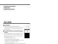
■
Power indicator:
When the power is turned on, the Power indicator lights.
If the Power indicator does not light when the power is turned on, the
protection function may be activated. Check whether there is any
indication of trouble.
■
The protection function is activated in the following
situations:
This unit is equipped with a protection function for protecting this unit
and your speakers from various accidents or problems that can occur.
When the protection function is triggered, the Power indicator goes off
and the amplifier stops operating.
• A speaker cable may be short-circuited.
• A speaker output may be in contact with the ground.
• The temperature of the internal parts may be higher than 120°C (248°F).
• The sigma servo connection may be erroneous.
• The fuse of this unit may be blown.
• The unit may be malfunctioning and sending DC signal to the speaker output.
• The grounding cable of this unit may not be connected with a metallic part which is
electrically connected with the negative terminal of the battery.
• The power control cable may not be connected to this unit.
• The grounding cable of the center unit (cassette receiver, CD receiver, etc.) may not be
connected with a metallic part which is electrically connected with the negative terminal of
the battery.
5
Power indicator
Power indicator

• The genuine-accessory car stereo shall have a maximum power output of no more than 25 W.
• Do not connect the speaker output leads from a power amplifier (Optional) to the speaker input
terminals of this unit, for this may cause malfunction or damage.
• Do not connect cables and leads to both RCA cable input jacks and the speaker input terminals
simultaneously, for this may cause malfunction or damage.
• Connect the power control lead to a power supply which can be turned ON/OFF by the ignition
key switch (ACC line).
With this connection, shock noise may be generated when the power of the genuine-accessory
car stereo is switched ON/OFF.
2CAUTION
6
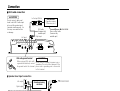
Connection
MONO
POWER AMPLIFIER
L
25Hz
15Hz
INFRASONIC
OFF
INPUT
SENSITIVITY(V)
LPF
FREQUENCY(Hz)
GND
R
LINE IN
0.3
0.5
1
2
3
4
5 0.2
150
100
70
50 200
LEFT RIGHT
SPEAKER LEVEL INPUT
- +
MONO
POWER AMPLIFIER
L
25Hz
15Hz
INFRASONIC
OFF
INPUT
SENSITIVITY(V)
LPF
FREQUENCY(Hz)
GND
R
LINE IN
0.3
0.5
1
2
3
4
5 0.2
150
100
70
50 200
LEFT RIGHT
SPEAKER LEVEL INPUT
■
RCA cable connection
CENTER UNIT
(Cassette receiver,
CD receiver, etc.)
Power control cable
(Commercially
available part)
RCA cable
(Commercially
available part)
Do not connect cables and
leads to both RCA cable input
jacks and the speaker input
terminals simultaneously, for
this may cause malfunction
or damage.
2CAUTION
RCA cable ground terminal
When using an RCA cable with
a ground lead attached, connect
the ground lead to this terminal.
Do not use this terminal for power source
grounding. This unit will be damaged if the
power source grounding wire is connected
to this terminal.
2CAUTION
Genuine-accessory
car stereo
■
Speaker level input connection
ACC
Battey
Left output (White)
Right output (Red)
Left input
Right input
Left input
Right input
Left output
Right output
Lead terminal
(Commercially
available parts)
Speaker level input terminals

7
POWER IN
FUSE(20A)
BATT
GND
FUSE(20A)
P.CON(REMOTE)
SPEAKER OUTPUT
20
20
SPEAKER OUTPUT
SERVO ΙΙ
∑
SERVO ΙΙ
∑
- +
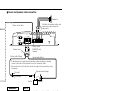
■
Power and Speakers cable connection
Power control
(REMOTE) lead
terminal
• Connect the ground cable to a metal part of the car chassis that
acts as an electrical ground passing electricity to the battery‘s
negative - terminal. Do not turn the power on if the ground cable
is not connected.
• When installing two amplifiers, connect a power tune-up cable to
each of them while taking care not to exceed the cable capacity.
• The power cable should be thick enough to supply the required
current and connected directly from the battery.
NOTE
• If a buzzing noise is heard from the speakers when the engine is running,
connect a line noise filter (optional) to each of the battery cable.
• Do not allow the cord to directly contact the edge of the iron plate by using
Grommets.
Terminal cover
Fire wall
Grommets
Battery
Ground cable (Black)
Battery cable (Yellow)
Round terminal (Large)
Power control cable
Power terminal
Pass battery and ground cables through supplied
terminal cover and connect to respective
terminals. After completing connections, fasten
terminal cover over terminal bracket.
Round terminal (Medium)
Round terminal (Small)
Speaker output cable terminal
Connect the speaker output
cables to these terminals.
Lead terminal
(Commercially
available part)
Speaker output
cable
To prevent fire caused by a
short in the wiring, connect
a fusible link or breaker
nearby the battery’s
positive terminal.
2WARNING
Subwoofer
Distribute the speaker cables and
sigma servo cables along the
same paths.

8
Sigma servo feed back
The sound reproduced through conventional amplifiers is distorted due to the
counterelectromotive force produced in the oscillating system of the speaker. The
counterelectromotive force is particularly high with the woofer which requires a large
drive mass.The sigma servo connection reduces distortion caused by the
counterelectromotive force by including the circuit up to the speaker terminals in the
negative feedback loop. This makes it possible to drive speakers with more fidelity to
the input signals and create a sharp bass sound image with few feeling of noise
interference.
The speaker cables and sigma servo cables should be distributed along the same paths.
• The extension of the negative feedback loop to include the speaker terminals makes it
necessary to connect the sigma servo terminals correctly. Incorrect connection may result in
sound degradation or other malfunction. If sound is not reproduced normally, check the
connection of the sigma servo terminals, etc.
• If the Sigma servo terminals are not connected, the sound may fluctuate or noise may occur.
Be sure to connect the Sigma servo terminals correctly.
• When connecting speakers in a parallel configuration, use speakers with an impedance of 4
ohms or more. Connecting speakers with smaller impedance than 4 ohms will cause
malfunction.
• The rated input of the speakers connected to this unit should be no less than the maximum
output of the amplifier. Otherwise malfunction may result.
Be specially careful in this when connecting speakers in a parallel configuration.
2CAUTION
NOTE
■
Basic sigma servo connection
■
Series connection
Make this cable as short as possible.
2CAUTION
■
Parallel connection (1)
The speaker cables connected to this unit
should be thick enough to supply the current
capacity of two speakers.
2CAUTION
This connection is possible only when the
speakers are identical and the speaker cables
are also of the same type and length.
2CAUTION
■
Simplified sigma servo connection
■
Parallel connection (2)
In case any of the connection examples above cannot be
used or if the speakers cannot be connected to the
speaker terminals, connect them to this unit as shown in
the figure.

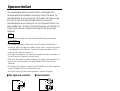
9
Specifications
Specifications subject to change without notice.
Audio Section
Max Power Output (2 Ω)................................................................................................400 W × 1
Rated Power Output (4 Ω)
(4 Ω)....................................................................................200 W × 1 (DIN45324, +B=14.4 V)
(2 Ω) ........................................................................................300 W × 1 (100 Hz, 0.8 % THD)
Frequency Response (+0, –1 dB) ............................................................................5 Hz ~ 200 Hz
Total Harmonic Distortion (Rated power)
#
............................................................0.01 % (100 Hz)
Sensitivity (MAX) (rated output)..............................................................................................0.2 V
Sensitivity (MIN) (rated output) ..............................................................................................5.0 V
Signal to Noise Ratio............................................................................................................100 dB
Input Impedance....................................................................................................................10 kΩ
Damping Factor..............................................................................More than 9900 (at ∑ connect)
Low Pass Filter Frequency (24 dB/oct.) ......................................................50 ~ 200 Hz (variable)
Infrasonic Filter Frequency (24 dB/oct.)..........................................................................15 / 25 Hz
# Sensitivity = Mini. , Through LPF (30 kHz)
General
Operating Voltage ..............................................................................14.4 V (11 ~ 16 V allowable)
Current Consumption (4 Ω, 14.4 V, 10% THD)........................................................................28 A
Dimensions (W × H × D) ................................................................................290 × 52 × 250 mm
Weight ..................................................................................................................................3.1 kg
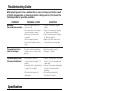
Troubleshooting Guide
What might appear to be a malfunction in your unit may just be the result
of slight misoperation or miswiring. Before calling service, first check the
following table for possible problems.
PROBLEM POSSIBLE CAUSE SOLUTION
No sound.
(No sound from one side.)
The output level is too
small (or too large).
The sound quality is bad.
(The sound is distorted.)
• Input (or output) cables are
disconnected.
• The connection of the sigma
servo terminals is wrong.
• Protection circuit may be
activated.
• The fuse may be blown
because the volume was too
high.
The input sensitivity adjusting
control is not set to the correct
position.
• The speakers cable are
connected with wrong + / -
polarity.
• A speaker cable is pinched by a
screw in the car body.
• The switches may be set
improperly.
• Connect the input (or output)
cables.
• Check the connection referring
to "Sigma servo feed back".
• Check connections by referring
to "Power indicator".
• Replace the fuse with a new
fuse and use a lower volume.
Adjust the control correctly
referring to "Controls".
• Connect them properly checking
the + / - of the terminals and
cables well.
• Connect the speaker cable again
so that it is not pinched by
anything.
• Set switches properly by
referring to "Controls".
-
 1
1
-
 2
2
-
 3
3
-
 4
4
-
 5
5
-
 6
6
-
 7
7
-
 8
8
-
 9
9


Kenwood KAC-816 User manual
- Category
- Car audio amplifiers
- Type
- User manual
Ask a question and I''ll find the answer in the document
Finding information in a document is now easier with AI
Related papers
-
Kenwood KAC-818 User manual
-
-
-
-
-
-
-
-
-