Page is loading ...

LN-23P WIRE FEEDER
Operator’s Manual
Save for future reference
Date Purchased
Code: (ex: 10859)
Serial: (ex: U1060512345)
IM922-A | Issue D ate 9-Oct
© Lincoln Global, Inc. All Rights Reserved.
For use with machines having Code Numbers:
11671, 11384
Register your machine:
www.lincolnelectric.com/register
Authorized Service and Distributor Locator:
www.lincolnelectric.com/locator

FOR ENGINE
powered equipment.
1.a. Turn the engine off before troubleshooting and maintenance
work unless the maintenance work requires it to be running.
____________________________________________________
1.b.Operate engines in open, well-ventilated
areas or vent the engine exhaust fumes
outdoors.
____________________________________________________
1.c. Do not add the fuel near an open flame
welding arc or when the engine is running.
Stop the engine and allow it to cool before
refueling to prevent spilled fuel from vaporiz-
ing on contact with hot engine parts and
igniting. Do not spill fuel when filling tank. If
fuel is spilled, wipe it up and do not start
engine until fumes have been eliminated.
____________________________________________________
1.d. Keep all equipment safety guards, covers and devices in
position and in good repair.Keep hands, hair, clothing and
tools away from V-belts, gears, fans and all other moving
parts when starting, operating or repairing equipment.
____________________________________________________
1.e. In some cases it may be necessary to remove safety
guards to perform required maintenance. Remove
guards only when necessary and replace them when the
maintenance requiring their removal is complete.
Always use the greatest care when working near moving
parts.
___________________________________________________
1.f. Do not put your hands near the engine fan.
Do not attempt to override the governor or
idler by pushing on the throttle control rods
while the engine is running.
___________________________________________________
1.g. To prevent accidentally starting gasoline engines while
turning the engine or welding generator during maintenance
work, disconnect the spark plug wires, distributor cap or
magneto wire as appropriate.
i
SAFETY
i
ARC WELDING CAN BE HAZARDOUS. PROTECT YOURSELF AND OTHERS FROM POSSIBLE SERIOUS INJURY OR DEATH.
KEEP CHILDREN AWAY. PACEMAKER WEARERS SHOULD CONSULT WITH THEIR DOCTOR BEFORE OPERATING.
Read and understand the following safety highlights. For additional safety information, it is strongly recommended that you
purchase a copy of “Safety in Welding & Cutting - ANSI Standard Z49.1” from the American Welding Society, P.O. Box
351040, Miami, Florida 33135 or CSA Standard W117.2-1974. A Free copy of “Arc Welding Safety” booklet E205 is available
from the Lincoln Electric Company, 22801 St. Clair Avenue, Cleveland, Ohio 44117-1199.
BE SURE THAT ALL INSTALLATION, OPERATION, MAINTENANCE AND REPAIR PROCEDURES ARE
PERFORMED ONLY BY QUALIFIED INDIVIDUALS.
WARNING
Mar ‘95
ELECTRIC AND
MAGNETIC FIELDS
may be dangerous
2.a. Electric current flowing through any conductor causes
localized Electric and Magnetic Fields (EMF). Welding
current creates EMF fields around welding cables and
welding machines
2.b. EMF fields may interfere with some pacemakers, and
welders having a pacemaker should consult their physician
before welding.
2.c. Exposure to EMF fields in welding may have other health
effects which are now not known.
2.d. All welders should use the following procedures in order to
minimize exposure to EMF fields from the welding circuit:
2.d.1.
Route the electrode and work cables together - Secure
them with tape when possible.
2.d.2. Never coil the electrode lead around your body.
2.d.3. Do not place your body between the electrode and
work cables. If the electrode cable is on your right
side, the work cable should also be on your right side.
2.d.4. Connect the work cable to the workpiece as close as
possible to the area being welded.
2.d.5. Do not work next to welding power source.
1.h. To avoid scalding, do not remove the
radiator pressure cap when the engine is
hot.
CALIFORNIA PROPOSITION 65 WARNINGS
Diesel engine exhaust and some of its constituents
are known to the State of California to cause can-
cer, birth defects, and other reproductive harm.
The engine exhaust from this product contains
chemicals known to the State of California to cause
cancer, birth defects, or other reproductive harm.
The Above For Diesel Engines
The Above For Gasoline Engines
LN™-23P

ii
ii
SAFETY
LN™-23P
ARC RAYS can burn.
4.a. Use a shield with the proper filter and cover
plates to protect your eyes from sparks and
the rays of the arc when welding or observing
open arc welding. Headshield and filter lens
should conform to ANSI Z87. I standards.
4.b. Use suitable clothing made from durable flame-resistant
material to protect your skin and that of your helpers from
the arc rays.
4.c. Protect other nearby personnel with suitable, non-flammable
screening and/or warn them not to watch the arc nor expose
themselves to the arc rays or to hot spatter or metal.
ELECTRIC SHOCK can
kill.
3.a. The electrode and work (or ground) circuits
are electrically “hot” when the welder is on.
Do not touch these “hot” parts with your bare
skin or wet clothing. Wear dry, hole-free
gloves to insulate hands.
3.b. Insulate yourself from work and ground using dry insulation.
Make certain the insulation is large enough to cover your full
area of physical contact with work and ground.
In addition to the normal safety precautions, if welding
must be performed under electrically hazardous
conditions (in damp locations or while wearing wet
clothing; on metal structures such as floors, gratings or
scaffolds; when in cramped positions such as sitting,
kneeling or lying, if there is a high risk of unavoidable or
accidental contact with the workpiece or ground) use
the following equipment:
• Semiautomatic DC Constant Voltage (Wire) Welder.
• DC Manual (Stick) Welder.
• AC Welder with Reduced Voltage Control.
3.c. In semiautomatic or automatic wire welding, the electrode,
electrode reel, welding head, nozzle or semiautomatic
welding gun are also electrically “hot”.
3.d. Always be sure the work cable makes a good electrical
connection with the metal being welded. The connection
should be as close as possible to the area being welded.
3.e. Ground the work or metal to be welded to a good electrical
(earth) ground.
3.f.
Maintain the electrode holder, work clamp, welding cable and
welding machine in good, safe operating condition. Replace
damaged insulation.
3.g. Never dip the electrode in water for cooling.
3.h. Never simultaneously touch electrically “hot” parts of
electrode holders connected to two welders because voltage
between the two can be the total of the open circuit voltage
of both welders.
3.i. When working above floor level, use a safety belt to protect
yourself from a fall should you get a shock.
3.j. Also see Items 6.c. and 8.
FUMES AND GASES
can be dangerous.
5.a. Welding may produce fumes and gases
hazardous to health. Avoid breathing these
fumes and gases. When welding, keep
your head out of the fume. Use enough
ventilation and/or exhaust at the arc to keep
fumes and gases away from the breathing zone. When
welding with electrodes which require special
ventilation such as stainless or hard facing (see
instructions on container or MSDS) or on lead or
cadmium plated steel and other metals or coatings
which produce highly toxic fumes, keep exposure as
low as possible and within applicable OSHA PEL and
ACGIH TLV limits using local exhaust or mechanical
ventilation. In confined spaces or in some circum-
stances, outdoors, a respirator may be required.
Additional precautions are also required when welding
on galvanized steel.
5. b. The operation of welding fume control equipment is affected
by various factors including proper use and positioning of
the equipment, maintenance of the equipment and the spe-
cific welding procedure and application involved. Worker
exposure level should be checked upon installation and
periodically thereafter to be certain it is within applicable
OSHA PEL and ACGIH TLV limits.
5.c.
Do not weld in locations near chlorinated hydrocarbon
vapors
coming from degreasing, cleaning or spraying operations.
The heat and rays of the arc can react with solvent vapors
to
form phosgene, a highly toxic gas, and other irritating prod-
ucts.
5.d. Shielding gases used for arc welding can displace air and
cause injury or death. Always use enough ventilation,
especially in confined areas, to insure breathing air is safe.
5.e. Read and understand the manufacturer’s instructions for this
equipment and the consumables to be used, including the
material safety data sheet (MSDS) and follow your
employer’s safety practices. MSDS forms are available from
your welding distributor or from the manufacturer.
5.f. Also see item 1.b.
Jan ‘09

iii
SAFETY
iii
LN™-23P
FOR ELECTRICALLY
powered equipment.
8.a. Turn off input power using the disconnect
switch at the fuse box before working on
the equipment.
8.b. Install equipment in accordance with the U.S. National
Electrical Code, all local codes and the manufacturer’s
recommendations.
8.c. Ground the equipment in accordance with the U.S. National
Electrical Code and the manufacturer’s recommendations.
CYLINDER may explode
if damaged.
7.a. Use only compressed gas cylinders
containing the correct shielding gas for the
process used and properly operating
regulators designed for the gas and
pressure used. All hoses, fittings, etc. should be suitable for
the application and maintained in good condition.
7.b. Always keep cylinders in an upright position securely
chained to an undercarriage or fixed support.
7.c. Cylinders should be located:
• Away from areas where they may be struck or subjected to
physical damage.
• A safe distance from arc welding or cutting operations and
any other source of heat, sparks, or flame.
7.d. Never allow the electrode, electrode holder or any other
electrically “hot” parts to touch a cylinder.
7.e. Keep your head and face away from the cylinder valve outlet
when opening the cylinder valve.
7.f. Valve protection caps should always be in place and hand
tight except when the cylinder is in use or connected for
use.
7.g. Read and follow the instructions on compressed gas
cylinders, associated equipment, and CGA publication P-l,
“Precautions for Safe Handling of Compressed Gases in
Cylinders,” available from the Compressed Gas Association
1235 Jefferson Davis Highway, Arlington, VA 22202.
WELDING and CUTTING
SPARKS can
cause fire or explosion.
6.a.
Remove fire hazards from the welding area.
If this is not possible, cover them to prevent
the welding sparks from starting a fire.
Remember that welding sparks and hot
materials from welding can easily go through small cracks
and openings to adjacent areas. Avoid welding near
hydraulic lines. Have a fire extinguisher readily available.
6.b. Where compressed gases are to be used at the job site,
special precautions should be used to prevent hazardous
situations. Refer to “Safety in Welding and Cutting” (ANSI
Standard Z49.1) and the operating information for the
equipment being used.
6.c. When not welding, make certain no part of the electrode
circuit is touching the work or ground. Accidental contact
can cause overheating and create a fire hazard.
6.d. Do not heat, cut or weld tanks, drums or containers until the
proper steps have been taken to insure that such procedures
will not cause flammable or toxic vapors from substances
inside. They can cause an explosion even
though
they have
been “cleaned”. For information, purchase “Recommended
Safe Practices for the
Preparation
for Welding and Cutting of
Containers and Piping That Have Held Hazardous
Substances”, AWS F4.1 from the American Welding Society
(see address above).
6.e. Vent hollow castings or containers before heating, cutting or
welding. They may explode.
6.f.
Sparks and spatter are thrown from the welding arc. Wear oil
free protective garments such as leather gloves, heavy shirt,
cuffless trousers, high shoes and a cap over your hair. Wear
ear plugs when welding out of position or in confined places.
Always wear safety glasses with side shields when in a
welding area.
6.g. Connect the work cable to the work as close to the welding
area as practical. Work cables connected to the building
framework or other locations away from the welding area
increase the possibility of the welding current passing
through lifting chains, crane cables or other alternate cir-
cuits. This can create fire hazards or overheat lifting chains
or cables until they fail.
6.h. Also see item 1.c.
6.I. Read and follow NFPA 51B “ Standard for Fire Prevention
During Welding, Cutting and Other Hot Work”, available
from NFPA, 1 Batterymarch Park, PO box 9101, Quincy, Ma
022690-9101.
6.j. Do not use a welding power source for pipe thawing.
Jan ‘09
Refer to http://www.lincolnelectric.com/safety for additional safety information.

vv
Thank You
for selecting a QUALITY product by Lincoln Electric. We want you
to take pride in operating this Lincoln Electric Company product
••• as much pride as we have in bringing this product to you!
Read this Operators Manual completely before attempting to use this equipment. Save this manual and keep it
handy for quick reference. Pay particular attention to the safety instructions we have provided for your protection.
The level of seriousness to be applied to each is explained below:
WARNING
This statement appears where the information must be followed exactly to avoid serious personal injury or loss of life.
This statement appears where the information must be followed to avoid minor personal injury or damage to this equipment.
CAUTION
Please Examine Carton and Equipment For Damage Immediately
When this equipment is shipped, title passes to the purchaser upon receipt by the carrier. Consequently, Claims
for material damaged in shipment must be made by the purchaser against the transportation company at the
time the shipment is received.
Please record your equipment identification information below for future reference. This information can be
found on your machine nameplate.
Product _________________________________________________________________________________
Model Number ___________________________________________________________________________
Code Number or Date Code_________________________________________________________________
Serial Number____________________________________________________________________________
Date Purchased___________________________________________________________________________
Where Purchased_________________________________________________________________________
Whenever you request replacement parts or information on this equipment, always supply the information you
have recorded above. The code number is especially important when identifying the correct replacement parts.
On-Line Product Registration
- Register your machine with Lincoln Electric either via fax or over the Internet.
• For faxing: Complete the form on the back of the warranty statement included in the literature packet
accompanying this machine and fax the form per the instructions printed on it.
• For On-Line Registration: Go to our
WEB SITE at www.lincolnelectric.com. Choose “Quick Links” and then
“Product Registration”. Please complete the form and submit your registration.
CUSTOMER ASSISTANCE POLICY
The business of The Lincoln Electric Company is manufacturing and selling high quality welding equipment, consumables, and cutting equip-
ment. Our challenge is to meet the needs of our customers and to exceed their expectations. On occasion, purchasers may ask Lincoln
Electric for advice or information about their use of our products. We respond to our customers based on the best information in our posses-
sion at that time. Lincoln Electric is not in a position to warrant or guarantee such advice, and assumes no liability, with respect to such infor-
mation or advice. We expressly disclaim any warranty of any kind, including any warranty of fitness for any customer’s particular purpose,
with respect to such information or advice. As a matter of practical consideration, we also cannot assume any responsibility for updating or
correcting any such information or advice once it has been given, nor does the provision of information or advice create, expand or alter any
warranty with respect to the sale of our products.
Lincoln Electric is a responsive manufacturer, but the selection and use of specific products sold by Lincoln Electric is solely within the control
of, and remains the sole responsibility of the customer. Many variables beyond the control of Lincoln Electric affect the results obtained in
applying these types of fabrication methods and service requirements.
Subject to Change – This information is accurate to the best of our knowledge at the time of printing. Please refer to www.lincolnelectric.com
for any updated information.

vi
TABLE OF CONTENTS
Page
Installation...................................................................................................................Section A
Technical Specifications.......................................................................................................A-1
Installation Instructions.........................................................................................................A-2
Safety Precautions ...............................................................................................................A-2
Input Cable....................................................................................................................A-2
Working Cable and Remote Voltage Sensing Work Lead ............................................A-2
Wire Drive Rolls and Guide Tubes................................................................................A-3
Optional Features Installation .......................................................................................A-3
Innershield Gun and Cable ...........................................................................................A-3
K-350 Adapter Kit..........................................................................................................A-3
K-276 Enclsoed 50 Lb Wire Reel Supt..........................................................................A-3
––––––––––––––––––––––––––––––––––––––––––––––––––––––––––––––––––––––––––––––––
Operation.....................................................................................................................Section B
Safety Precautions ...............................................................................................................B-1
Product Description..............................................................................................................B-1
Loading the Wire Reel..........................................................................................................B-1
Instructions For Loading Wire into LN-23......................................................................B-2
Drive Roll Pressure ..............................................................................................................B-3
Adjusting Wire Feed Speed and Votlage .............................................................................B-3
Marking the Weld .................................................................................................................B-3
––––––––––––––––––––––––––––––––––––––––––––––––––––––––––––––––––––––––––––––––
Accessories.....................................................................................................Section C
Optional Equipment...............................................................................................C-1
Gun and Cable Assemblies ............................................................................C-1
K-350 Adapter Kit
......................................................................................................
C-1
K-276 Enclosed Wire Reel Support..............................................................................
C-1
––––––––––––––––––––––––––––––––––––––––––––––––––––––––––––––––––––––––
Maintenance ....................................................................................................Section D
Safety Precautions ................................................................................................D-1
Replacing or Reversing Drive Rolls.......................................................................D-1
Removing Idle Roll Assembly................................................................................D-1
Gun and Cable ......................................................................................................D-1
Wire Drive Assembly Maintenance........................................................................D-1
Circuit Protection...................................................................................................D-2
Nameplates ...........................................................................................................D-2
Power Soruce........................................................................................................D-2
––––––––––––––––––––––––––––––––––––––––––––––––––––––––––––––––––––––––
Troubleshooting..............................................................................................Section E
Safety Precautions.................................................................................................E-1
How to Use Troubleshooting Guide.......................................................................E-1
Troubleshooting ..........................................................................................E-2 to E-3
––––––––––––––––––––––––––––––––––––––––––––––––––––––––––––––––––––––––
Connection and Wiring Diagrams..................................................................Section F
Parts List
....................................................................................................P-552, P-103, P-107
––––––––––––––––––––––––––––––––––––––––––––––––––––––––––––––––––––––––

TEMPERATURE RANGE
OPERATION: - 30
o
C
o
* to +40
o
C (- 22
o
F to +104
o
F)
STORAGE: - 40
o
C to +40
o
C (- 40
o
F to +104
o
F)
ENVIRONMENTAL RATING
OPERATING ARC VOLTAGE
Constant Voltage (CV) 14-50VDC (90VDC Maximum OCV)
RATED CURRENT
250-350 Amps 60% Duty Cycle
(Depending on Gun Used)
WIRE SPEED RANGE
30-170 Inches Per Minute (IPM)
(1.18-6.70 mm)
RECOMMENDED ELECTRODE WIRE SIZES
.068” INNERSHIELD
.072
” INNERSHIELD
5/64
” INNERSHIELD
PHYSICAL DIMENSIONS
HEIGHT WIDTH DEPTH WEIGHT
20.5 Inches 9.0 Inches 19.0 Inches 27 lbs
(520.7 mm) (228.6 mm) (482.6mm) (12.3 kg)
EENNVVIIRROONNMMEENNTTAALL RRAATTIINNGG
A-1
INSTALLATION
LN™-23P
A-1
TECHNICAL SPECIFICATIONS – LN™-23P
*At temperatures below 0°C, the gun cable may require a warm up operating time to improve flexibility.

A-2
INSTALLATION
A-2
LN™-23P
INPUT CABLE
The standard 25 foot input cable between the LN™-
23P and the power source with Adapter Kit consists of
a six-conductor control cable and a 1/0 electrode
cable. The control cable has lugged leads on the
power source end and a polarized plug on the wire
feeder end. With the power source turned off,
install the input cable per the following instructions:
• Connect the end of the control cable with the
lugged leads to the LN™-23P Adapter Kit. Connect
the electrode cable to the negative output stud on
the power source.
NOTE: If two LN™-23P’s are connected to an
Adapter Kit, connect the feeder that will be used at
the lowest voltage setting to Feeder “A” terminal
strip. If one LN™-23P is used, connect it to Feeder
“A” terminal strip.
• Connect the input control cable polarized plug into
the mating 6 pin receptacle on the rear of the con-
trol section of the LN™-23P. Tighten the threaded
locking collar until the connector is completely
seated.
• Unclip the rubber retaining strap that holds the wire
enclosure cover in place and remove the cover.
Push the wire drive section door latch towards the
rear of the LN™-23P and open the door. Route the
electrode cable through the large rubber grommet
in the rear of the wire feed section and connect the
lug to the brass conductor block at the front of
motor-gearbox assembly using the bolt provided.
Attach the control cable strain relief hook to bracket
on the frame of the LN™-23P.
SAFETY PRECAUTIONS
ELECTRIC SHOCK can kill.
• Only qualified personnel should
perform this installation, maintenance
and troubleshooting work.
• Turn off the input power at the fuse box before
working on other equipment connected to the
welding system at the disconnect switch or fuse
box before working on this equipment.
• Do not touch electrically hot parts.
------------------------------------------------------------------------
WARNING
WORK CABLE AND REMOTE VOLTAGE
SENSING WORK LEAD
• Connect a work cable of sufficient size and length,
per the following table, between the proper output
stud on the power source and the work. Be sure
the connection to the work makes tight metal to
metal contact.
Above cable sizes are based on a maximum voltage drop of
4.3 volts in the combined lengths of electrode and work
cable at 350 amps.
•
Connect a 12 AWG or larger rubber covered flexi-
ble lead physically suitable for the installation to the
voltage sensing work lead coming the Adapter Kit.
For convenience, wrap the voltage sensing lead
around the work lead and tape in place. Connect
directly to the work or to the work cable connection
on the work piece. This lead supplies the voltage to
the voltmeter in the LN™-23P and also supplies
the power to the LN™-23P drive motor.
Electrode Work Copper Copper
Cable Cable Electrode Work Cable
Length Length Cable Size Size
0-25 ft. 0-75 ft. 1/0 1/0
0-25 76-125 1/0 2/0
26-75 26-75 2/0 2/0
26-75 76-125 2/0 4/0
76-100 76-125 3/0 4/0

A-3
INSTALLATION
LN™-23P
A-3
•
DC-600: Attach the triangular mounting plate to the
shock mounted plate of the Adapter with three of
the #10 self-tapping screws provided. Attach the
triangular plate to the side of the DC-600 adjacent
to the control terminal strips using two roof screws
and one front panel screw. Connect the Adapter
control cable to the DC-600 terminal strips power
the proper connection diagram.
•
Other Power Sources: Mount the Adapter Kit to the
side of the power source or some convenient loca-
tion so its control cable can be connected to the
power source 14 pin connector. Use the shock
mounted mounting plate as a template to locate the
four 5/32" diameter holes that must be drilled in the
case side. (Use caution not to drill into or get chips
into any internal components.) Mount the Adapter
Kit with four of the #10 self-tapping screws provid-
ed. Connect the Adapter control cable to power
source terminal strips per the proper connection
diagram.
K-276 ENCLOSED 50lb. WIRE REEL SUPPORT
Installation and loading instructions (M-13153) are
supplied with the kit.
------------------------------------------------------------------------
WIRE DRIVE ROLLS AND GUIDE TUBES
The LN™-23P is shipped with the proper drive rolls
and guide tubes factory installed. Do not adjust the
idle roll tension adjusting screw. If the idle roll tension
must be relieved temporarily, see “A” and “B” of
Maintenance Section.
OPTIONAL FEATURES INSTALLATION
INNERSHIELD GUN AND CABLE
•
Unclip the rubber retaining strap that holds the wire
enclosure cover in place and remove the cover.
•
Push the wire drive section door latch towards the
rear of LN™-23P and open door.
•
Loosen the gun locking set screw in the conductor
block on the front of the gear box with a 3/16 hex
Allen wrench.
•
Lay the cable out straight. Insert the connector on
the conductor cable thru the large grommet in the
front of the wire drive section and into the brass
block on the front of the gear box. Make sure it is
all the way in and tighten the locking set screw with
a 3/16 hex Allen wrench. Keep this connection
clean and bright.
•
Connect the 3 pin gun trigger connector to the
lower receptacle.
•
If the gun cable being used has a reduced speed
switch, connect the 4 pin reduced speed switch
connector to the upper receptacle. If the reduced
speed switch is not used, install the protective cap
on the upper receptacle.
K-350 ADAPTER KIT– Turn off power source and all
power to power source.
•
SAM-400 Engine Welders: Attach the shock
mounted mounting plate to the front of the SAM
electrical component panel to left of the relay case
with 4 of the #10 self-tapping screws provided.
Older models require the drilling of 4 5/32 dia.
holes into the panel. Connect the adapter control
cable to the SAM terminal strips per the proper
connection diagram.
CAUTION

B-1
OPERATION
B-1
PRODUCT DESCRIPTION
The K316L-[ ] / LN™-23P is a lightweight, portable
wire feed unit which includes calibrated wire speed
control, voltage control, wire drive with enclosed 14 lb.
Wire reel, analog voltmeter and various input control
and electrode cable lengths.
The feeder is designed for welding with 14 pound coils
of .068 and 5/64 Innershield self-shielding electrodes
using a constant voltage type DC power Source.
When shipped, it is internally connected for welding
with electrode negative polarity (DC–). Depending
upon which gun and cable is used, its rating is either
350 amps or 250 amps at 60% duty cycle.
The wire speed control has a calibrated dial plate with
a range of 30 to 170 inches per minute and allows
quick and easy setting of the procedure wire feed
speed. The wire speed is not affected by changes in
the arc voltage setting even though the wire feed cir-
cuit is powered by arc voltage. A two-position switch,
which is mounted on the gun and a reduced speed cir-
cuit, allows selection of the preset wire speed or 83%
of the preset speed.
A low voltage gun trigger circuit turns both the power
source output and wire feed on and off. The gun trig-
ger circuit is interlocked by a weld current sensing
reed switch so that while welding, the gun trigger
switch does not have to be held closed. The welding
process is stopped by pulling the gun away from the
work. The electrode remains cold until the gun trigger
is operated.
The LN™-23P includes a voltage control which con-
trols the power source output. Also included is an ana-
log voltmeter which allows easy setting of the proce-
dure arc voltage at the LN™-23P.
LOADING THE WIRE REEL
(For machines that have code numbers Lower
than 11383.)
• Lay the LN™-23P flat with the wire reel cover up,
unclip the rubber retaining strap, and remove the
cover.
• Remove the center clamping nut and the cover
plate from the wire reel.
• Unpack the 14-pound coil of wire. Be sure not to
bend the side tangs of the coil liner and straighten
any tangs that may have been bent.
• Place the coil on the wire reel so the coil will
unwind when it rotates in a clockwise direction.
• Remove the start end of the coil from its holding
slot in the coil liner, cut off the bent end, straighten
the first few inches and thread it through the wire
feed conduit connected to the wire enclosure until
several inches of electrode are exposed. Be careful
not to release the electrode until it is through the
wire feed conduit; otherwise, it may unwind and
tangle.
• Be sure all the lower tangs of the coil liner are flush
against the back half of the wire reel and that none
of the upper tangs are bent in against the coil.
• Replace the reel cover plat and the center clamp-
ing nut.
• Replace the cover of the wire reel enclosure and
clip the retaining strap in place.
• Pull about 2 feet of the exposed end of the elec-
trode through the wire feed conduit. Slide the insu-
lator all the way up on the wire feed conduit.
Make a single, free loop in the electrode and feed
the end into the section of wire feed conduit con-
nected to the gearbox. Press the gun trigger and
push the electrode into the drive rolls. Release the
electrode as soon as it is picked up by the drive
rolls. Continue feeding electrode until the excess
length is fed through the drive rolls. Watch the sin-
gle loop and guide it if necessary to make certain it
untwists without kinking. Do not feed electrode
through cable at this time. Slide insulator down on
wire feed conduit until it slips over section of con-
duit connected to gearbox.
• Set the unit upright on floor, straighten the gun
cable, press the gun trigger, and feed electrode
though the gun and cable assembly.
SAFETY PRECAUTIONS
ELECTRIC SHOCK can kill.
• Do not touch electrically live parts
such as output terminals or internal
wiring.
• When inching with gun trigger, electrode and
drive mechanism are “hot” to work and ground
and could remain energized several seconds
after the gun trigger is released.
• Turn OFF input power at welding power source
before installation or changing drive roll and/or
guide tubes.
• Welding power source must be connected to
system ground per the National Electrical Code
or any applicable local codes.
• Only qualified personnel should perform this
installation.
------------------------------------------------------------------------
WARNING
LN™-23P

B-2
OPERATION
B-2
LN™-23P
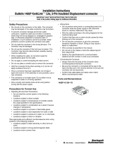
2. Remove compartment cover along with plastic wire
reel brake and reel cover. Pull wire end from spool
and route it through the liner opening that is mount-
ed inside the wire reel case.
3. Pull 2-3 ft. of wire through upper conduit cable
piece as shown in picture below.
ELECTRIC SHOCK can kill.
• Do not touch electrically hot parts.
5. Turn on power and trigger the gun to take up slack
in the wire.
6. Connect the upper conduit and lower Conduit
pieces as shown in picture below.
Reel Cover
2-3 Feet
Feed Wire thru
Liner Opening.
WARNING
Watch for kinks when
feeding wire thru conduit.
Upper and Lower conduit.
4. Add Reel Cover. Form a loop with the wire and
route it through the lower conduit piece and past
the drive rolls as shown below .
Feed into Drive
Rolls in this area.
Loop
Enter Wire thru conduit piece
Add Reel Cover
INSTRUCTIONS FOR LOADING WIRE
INTO LN™-23P
(For machines that have code numbers Higher
than 11384.)
1. With the power shut off and input leads going to the
wire feeder disconnected, lay LN™-23P down with
wire reel facing up.

B-3
OPERATION
B-3
DRIVE ROLL PRESSURE
• Do not adjust the drive roll pressure. If the idle roll
tension must be relieved temporarily, see
(Maintenance Section).
ADJUSTING WIRE FEED SPEED AND
VOLTAGE
Set the wire feed as specified in the procedures using
the calibrated dial on the back of the LN™-23P control
box. When the reduced wire speed switch (mounted
on the gun handle) is in Position No. 1, the wire feed
speed will be that which is indicated on the dial. In
Position No. 2, the wire feed speed will be 83% of the
figure indicated on the dial.
Set the voltage by adjusting the voltage control while
welding until the voltage specified in the procedures is
indicated on the meter. The meter reading with the
power source on but not welding is the open circuit
voltage. With some power sources, this voltage may
be significantly higher than welding voltage.
When establishing initial procedures, start with the
voltage control set near minimum. Strike an arc on
scrap steel. If the arc fails to start, increase the volt-
age settings until the arc can be established.
NEVER set the power source open circuit voltage
higher than 50
(1)
volts. The LN™-23P will not feed wire
when the voltage is higher than 50
(1)
volts.
When using the CV Converter or the DC-600 and
inching wire (not welding) at open circuit voltages
below 20 volts or above 25 volts, feeding may be
unsteady or the wire speed may vary from that set on
the dial. This condition does not exist while welding.
Minimum usable arc voltage is 14 volts.
NOTE: For improved readability of the voltmeter in
some applications, the voltmeter guard may be
installed rotated end for end. This will result in the pro-
tective bars crossing the meter face in a different loca-
tion.
MAKING THE WELD
Be sure the proper contact tip for either .068" or 5/64"
wire, as appropriate, is in the gun. The thread protec-
tor should cover the external threads on the nozzle.
Loosen the insulated screw on the side of the gun,
rotate the gun nozzle to the position most convenient
for the particular application, and retighten the insulat-
ed screw.
When welding, set the wire feeder on the floor or hang
it near the work area as convenient. Place the LN™-
23P to minimize the amount of spatter falling onto it.
Always avoid sharp bends and keep the gun cable
as straight as practical.
Be sure the electrode cable, work cable, and control
lead are connected and the power source is on.
Press the gun trigger to feed the electrode out of the
gun. Use a visible strikeout equal to the electrical
strikeout specified in the procedures for the wire being
used.
Position the gun with the wire just off or lightly touch-
ing the work. Press the gun trigger to start the arc.
Once the arc is established, the gun trigger can be
released while welding. The gun trigger interlock cir-
cuit automatically keeps the welding process on. At
the end of the weld, pull the gun away from the work.
When not welding, always store the gun in the insulat-
ed tube on the front of wire feeder.
While welding with one feeder of a two-feeder installa-
tion the electrode of the second feeder is “HOT”. Only
one feeder at a time can be used for welding. Do not
press the gun trigger of the idle feeder while the other
feeder is being used since this can shut down the
feeder being used for welding.
LN™-23P
(1)
45 volts on DC-600.

C-1
ACCESSORIES
LN™-23P
C-1
OPTIONAL EQUIPMENT
GUN AND CABLE ASSEMBLIES
K-350 ADAPTER KIT
Required when using the LN™-23P on any constant
voltage power source. Either one or two LN™-23P’s
can be connected to the Adapter. If two LN™-23P’s
are connected, they can be set for different proce-
dures. The Adapter circuit is interlocked so only one
LN™-23P can be used at a time.
Note: A K350 Adapter Kit is not applicable when
connecting a LN™-23P (Code 10892, 10917, 10918)
to a V350-Pipe.
K-276 ENCLOSED WIRE REEL SUPPORT
Bolts to the LN™-23P frame for feeding wire from
standard 50 lb. Innershield coils. Includes enclosure
and door to keep the dirt out; also includes wire reel
brake assembly.
Type K-355-10* K-345-10* K-264-8 K-361-10 K-406*
Length: 10 feet 10 feet 8 feet 10 feet Linconditioner Gun 10 ft.
(15 ft. Exhaust Hose)
Rated Welding
Current: 250 Amps 350 Amps 250 Amps 350 Amps 350 Amps
Duty Cycle 60% 60% 60% 60% 60%
Electrode Sizes .068, .072, 5/64 .068, .072, 5/64 068, .072, 5/64 068, .072, 5/64 068, .072, 5/64
Reduced Speed
Switch stod. stod. None None stod.
Sizes 5/64 5/64 5/64 5/64 5/64
Nozzle Angle 90E 90E 62E 62E 68E
Weight 7.0 lbs. 89.3 lbs. 5.2 lbs. 7.5 lbs. 16.0 lbs.
* Recommended for pipe welding applications.
All guns include one each .068/.072 tip, 5/64 tip, and a thread protector**. The K-264-8 also includes an insulated guide for
3/4" to 1-1/2" strikeout. The K-361-10 also includes an insulated guide for 2" strikeout.** The K-406 includes an insulated
guide for 2" to 1" strikeout, but no thread protector.

D-1
MAINTENANCE
D-1
REMOVING IDLE ROLL ASSEMBLY
Remove the idle roll tension screw (Item 1), tension
spring retainer (Item 4), and tension spring (Item 5).
Pivot the idle roll assembly away from the gearbox
and lift it off the pivot pin (Item 6).
To re-assemble, replace idle roll assembly, tension
spring, retainer, and tension screw. Tighten the ten-
sion screw until it bottoms, and then back it out two
complete turns.
GUN AND CABLE MAINTENANCE
Remove spatter from tip after each ten minutes of arc
time or as required.
Replace worn contact tips and thread protectors as
required.
Replace worn spring liners in nozzles. The life of the
spring can be doubled by rotating it 180°.
Clean cables after using approximately 300 pounds of
electrode. Remove the cable from the wire feeder and
lay it out straight on the floor. Remove the contact
nozzle tip from the gun. Using an air hose and only
partial pressure, gently blow out the cable from the
gun end. (Too much pressure at the start will cause
the dirt to form a plug.) Flex the cable over its entire
length and again blow out the cable. Repeat this pro-
cedure until no further dirt comes out.
Before any gun is disassembled, remove unit from the
wire feeder or shut off the power source.
WIRE DRIVE ASSEMBLY MAINTENANCE
Every 500 pound s of electrode, the drive roll section
should be inspected and cleaned out if necessary. Do
not use a solvent for cleaning the idle roll as it may
wash lubricant out of the bearing.
Replace drive rolls as required. Drive rolls should be
worn on both sides before replacing. See “A” of this
section.
Check the motor brushes every six months. Replace if
they are less than 1/4" long.
Every year examine the gear box and paint the gear
teeth with moly-disulfide filled grease.
LN™-23P
SAFETY PRECAUTIONS
Have qualified personnel do the maintenance
work. Turn the engine off before working inside
the machine. In some cases, it may be
necessary to remove safety guards to perform
required maintenance. Remove guards only
when necessary and replace them when the
maintenance requiring their removal is
complete. Always use the greatest care when
working near moving parts.
------------------------------------------------------------------------
ELECTRIC SHOCK can kill.
• Do not touch electrically live parts or
electrode with skin or wet clothing.
• Insulate yourself from work and
ground
• Always wear dry insulating gloves.
------------------------------------------------------------------------
See additional warning information
throughout this operator’s manual and
the Engine manual as well.
-----------------------------------------------------------
WARNING
REPLACING OR REVERSING DRIVE
ROLLS (See drawing below.)
Loosen idle roll tension screw (Item 1) to release pres-
sure between idle roll and drive rolls.
Remove hex head screw (Item 2) with a 1/2" wrench
and remove the drive roll clamping collar (Item 3).
Remove drive rolls from shaft.
Wipe the drive roll surfaces clean. Then install drive
rolls. If reversing drive rolls, turn drive rolls over so
unworn teeth face each other.
Replace clamping collar and hex head screw.
Tighten the idle roll tension screw until it bottoms and
then back it out two complete turns.

D-2
MAINTENANCE
LN™-23P
D-2
CIRCUIT PROTECTION
Circuit Breaker – The 3.5 amp circuit breaker located
on the rear of the unit normally trips only when an
overload occurs because of excessive loading in the
wire feed cable or a defective motor or control compo-
nents. After allowing a few minutes for cooling, push
the reset button and weld. If it trips again, be sure the
gun cable is not being excessively bent, is clean, and
is the proper size for the wire diameter being fed. If it
still trips, look for a defective electrical component.
NAMEPLATES
Whenever routine maintenance is performed on this
machine — or at least yearly — inspect all name-
plates and labels for legibility. Replace those which
are no longer clear. Refer to the parts list for the
replacement item number.
POWER SOURCE
One or two LN™-23P’s can be connected to a DC power source (constant voltage) with a K350-1 Adapter Kit. If
two LN™-23P’s are connected, they can be set for different procedures but only one can be used at a time.
NOTE: The K350 must be used on power sources with terminal strip connections only.
Power source connection diagrams:
M17323
M14272
LN™-23P Power Sources
1. Classic II, Classic III, Classic IIWI, or SA-250 with K350-1 Adapter Kit and K623-1 Wire Feed Module.
2. Commander 300, Commander 400 or Commander 500 with K350-1 Adapter Kit.
3. Ranger 250 , Ranger 275, or Ranger 305G with K350-1 Adapter Kit.
4. CV-300, CV-400, DC-400, DC-600, DC655 or V300 with K350-1 Adapter Kit.
5. SAE-400 or SAE-400 Weld ’N Air with K385-1 CV Adapter & K350 Adapter Kit.
6. LN23-P (Code 10892,10917,10918) used only with V350-Pipe. K350 Adapter Kit is not applicable.

E-1
TROUBLESHOOTING
E-1
If for any reason you do not understand the test procedures or are unable to perform the tests/repairs safely, contact your
Local Lincoln Authorized Field Service Facility for technical troubleshooting assistance before you proceed.
CAUTION
This Troubleshooting Guide is provided to help you
locate and repair possible machine malfunctions.
Simply follow the three-step procedure listed below.
Step 1. LOCATE PROBLEM (SYMPTOM).
Look under the column labeled “PROBLEM (SYMP-
TOMS)”. This column describes possible symptoms
that the machine may exhibit. Find the listing that
best describes the symptom that the machine is
exhibiting.
Step 2. POSSIBLE CAUSE.
The second column labeled “POSSIBLE CAUSE” lists
the obvious external possibilities that may contribute
to the machine symptom.
Step 3. RECOMMENDED COURSE OF ACTION
This column provides a course of action for the
Possible Cause, generally it states to contact your
local Lincoln Authorized Field Service Facility.
If you do not understand or are unable to perform the
Recommended Course of Action safely, contact your
local Lincoln Authorized Field Service Facility.
HOW TO USE TROUBLESHOOTING GUIDE
Service and Repair should only be performed by Lincoln Electric Factory Trained Personnel.
Unauthorized repairs performed on this equipment may result in danger to the technician and
machine operator and will invalidate your factory warranty. For your safety and to avoid Electrical
Shock, please observe all safety notes and precautions detailed throughout this manual.
__________________________________________________________________________
WARNING

E-2
TROUBLESHOOTING
E-2
LN™-23P
Observe all Safety Guidelines detailed throughout this manual
If for any reason you do not understand the test procedures or are unable to perform the tests/repairs safely, contact your
Local Lincoln Authorized Field Service Facility for technical troubleshooting assistance before you proceed.
CAUTION
PROBLEMS
(SYMPTOMS)
POSSIBLE
CAUSE
RECOMMENDED
COURSE OF ACTION
Motor won’t run.
Wire will not feed, or erratic feeding.
Erratic arc action.
1. Circuit breaker tripped.
2. OCV is above 50 volts (45 volts
on DC-600).
3. Wrong polarity – unit is shipped
internally connected to operate
on negative polarity only.
4. Remote voltage sensing work
lead not connected to work.
5. Electrode lead not connected to
LN™-23P.
6. Control cable not properly con-
nected to CV Converter or
Adapter Kit.
7. Faulty gun trigger or broken con-
trol wires.
8. Faulty control circuit.
9. Faulty CV Converter, Adapter Kit
or Power Source.
1. Gun cable being excessively
bent.
2. Dirty gun cable.
3. Loop of wire caught on bent tang
in wire reel.
4. Worn drive rolls.
5. Improper idle roll tension setting.
1. Worn tip.
2. Incorrect wire feed speed or volt-
age.
3. Poor work lead connection.
If all recommended possible areas
of misadjustment have been
checked and the problem persists,
Contact your local Lincoln
Authorized Field Service Facility.

E-3
TROUBLESHOOTING
E-3
LN™-23P
Observe all Safety Guidelines detailed throughout this manual
If for any reason you do not understand the test procedures or are unable to perform the tests/repairs safely, contact your
Local Lincoln Authorized Field Service Facility for technical troubleshooting assistance before you proceed.
CAUTION
PROBLEMS
(SYMPTOMS)
POSSIBLE
CAUSE
RECOMMENDED
COURSE OF ACTION
Improper wire speed control.
Can’t obtain required voltage.
1. Faulty printed circuit board, faulty
rheostat, or faulty motor.
1. Defective power source of CV
Converter.
2. On SAM welders, constant volt-
age control must be adjusted to
give required voltage and mode
switch must be set to constant
voltage position.
3. On DC-600 and R3S welders,
fine voltage control switch must
be set to remote position.
4. Broken lead(s) in 75-76-77 (A-
B-C) control circuit.
5. Defective voltage control rheo-
stat.
If all recommended possible areas
of misadjustment have been
checked and the problem persists,
Contact your local Lincoln
Authorized Field Service Facility.

F-1
DIAGRAMS
F-1
LN™-23P
NOTE: This diagram is for reference only. It may not be accurate for all machines covered by this manual. The specific diagram for a particular code is pasted inside
the machine on one of the enclosure panels. If the diagram is illegible, write to the Service Department for a replacement. Give the equipment code number.
LN™-23P ADAPTER KIT WIRING DIAGRAM
M-14247
2-19-82

F-2
DIAGRAMS
F-2
LN™-23P
M17514
12-01
1
3
4
5
6
2
6
4 2
1
5
*
RELAY P.C. BOARD
3
1CR
21
521
609
608
610
604B
607
75
B
A
608
75A
75B
4
76A
76B
602
604
7
5
76
7
7
521
602
604
7
5
76
77
5
21
602
2CR
B
A
609
521B
521A
2B
2A
31
32
4
77
76
75
21
607
606
605
A
A
A
A
A
A
A
A
A
(J)
(A)
(D)
(C)
(H)
A
A
(E)
(F)
(G)
(I)
(K)
(B)
31
32
4
2
77
76
75
GND
2B
2 1
4
7
5
8
3
6
9
4
610
3
2
1
6
5
4
789
604A
76
2A
INDICATES CONNECTOR
CAVITY NUMBER
A.N.S.I. ELECTRICAL SYMBOLS PER E1537
COLOR LEGEND
R=RED
B=BLACK
8 CONDUCTOR CONTROL CABLE
"A" WIRE FEEDER "B" WIRE FEEDER
TERMINAL STRIP
TERMINAL STRIP
24V. CONTROL TRANSFORMER
2C
21
521
R
R
B
B
606
605
ICR & 2CR - 3 PDT, 24V.D.C.
AMPHENOL
SENSE LEAD
WIRING DIAGRAM
NOTE: This diagram is for reference only. It may not be accurate for all machines covered by this manual. The specific diagram for a particular code is pasted inside
the machine on one of the enclosure panels. If the diagram is illegible, write to the Service Department for a replacement. Give the equipment code number.
/