WinSystems SAT-520PLUS Operating instructions
- Category
- Interface cards/adapters
- Type
- Operating instructions

OPERATIONS MANUAL
SAT-520PLUS
WinSystems reserves the right to make changes in the circuitry
and specifications at any time without notice.
Copyright 2002 by WinSystems. All Rights Reserved.
NOTE: This manual has been designed and created for use as part of the WinSystems’
Technical Manuals CD and/or the WinSystems’ website. If this manual or any portion of
the manual is downloaded, copied or emailed, the links to additional information (i.e.
software, cable drawings) will be inoperable.

REVISION HISTORY
P/N 403-0310-000B
ECO Number Date Code Rev Level
ORIGINATED 021126 B
ECO 04-31 040413 B1
070223 B2*
* revised for format, only

Table of Contents
Visual Index – Quick Reference
. . . . . . . . . . . . . . . . . . . . . . . . . . . . i
Top View – Connectors i
Top View – Jumpers ii
Introduction
. . . . . . . . . . . . . . . . . . . . . . . . . . . . . . . . . . . . . . . . . . . 1
General Information
. . . . . . . . . . . . . . . . . . . . . . . . . . . . . . . . . . . . . 1
Features 1
General Description 1
SAT-520Plus Technical Reference
. . . . . . . . . . . . . . . . . . . . . . . . . . 2
AMD Elan SC520 Chipset/Processor 2
Memory Selection and Installation 3
Power/Reset Connection 3
BIOS Extension Socket 4
Floppy Disk Interface 4
IDE Interface 5
DiskOnChip Configuration 5
Serial Interface 6
Serial Port I/O Definitions 7
Ethernet Controller 8
Parallel I/O 9
VGA Configuration 10
Flat Panel Output Connection 11
Parallel Printer Port 11
Keyboard Interface 12
Multi-I/O Connector 12
Mouse Interface 12
Real-Time Clock/Calendar and CMOS Setup RAM 13
Watchdog Timer Configuration 13
Status LED 13
Speaker/Sound Interface 13
PC/104 Bus Interface 14
PC/104-Plus Interface 16
Phoenix BIOS
. . . . . . . . . . . . . . . . . . . . . . . . . . . . . . . . . . . . . . . . . . 17
Phlash Utility
. . . . . . . . . . . . . . . . . . . . . . . . . . . . . . . . . . . . . . . . . . 30
Logo Utility
. . . . . . . . . . . . . . . . . . . . . . . . . . . . . . . . . . . . . . . . . . . . 30
I/O Port Map
. . . . . . . . . . . . . . . . . . . . . . . . . . . . . . . . . . . . . . . . . . 32
Interrupt Map
. . . . . . . . . . . . . . . . . . . . . . . . . . . . . . . . . . . . . . . . . . 33
Datasheet Reprint Intel 82C55A
. . . . . . . . . . . . . . . . . . . . . . . . . . . 35
Cable Drawings
. . . . . . . . . . . . . . . . . . . . . . . . . . . . . . . . . . . . . . . . . .35
Software Drivers & Examples
. . . . . . . . . . . . . . . . . . . . . . . . . . . . . . 35
& LEDs

SAT-520Plus Mechanical Drawing
. . . . . . . . . . . . . . . . . . . . . . . . . . . 37
Jumper Reference – (Drawings ONLY)
. . . . . . . . . . . . . . . . . . . . . . . 38
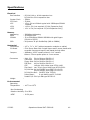
Specifications
. . . . . . . . . . . . . . . . . . . . . . . . . . . . . . . . . . . . . . . . . . . 40
Warranty Repair Information

070223 Operations Manual SAT-520PLUS i
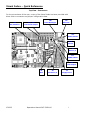
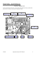
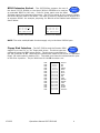
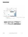
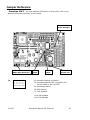
Visual Index – Quick Reference
Top View - Connectors
For the convenience of the user, a copy of the Visual Index has been provided with
direct links to connector and jumper configuration data.
J16
PC/104-Plus
J19, J20
Flat Panel Output
J18
Panel Backlight
J17
Ethernet
J14
Mouse
J13
Power/Reset
J15
CRT Output
J11
COM3/COM4
J9
Multi I/O
J6
IDE
J8
Parallel I/O
J5
Floppy Drive

070223 Operations Manual SAT-520PLUS ii
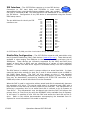
Visual Index – Quick Reference
Top View - Jumpers
For the convenience of the user, a copy of the Visual Index has been provided with
direct links to connector and jumper configuration data.
J12
Panel Backlight
J3
VBAT/DOC/Watchdog
J1
Parallel VIO
J7
COM1
J10
COM2
D1
IDE Status LED
D10
Ethernet Link
D9
Ethernet Speed
D8
Ethernet Activity
& LEDs

070223 Operations Manual SAT-520PLUS 1
Introduction
This manual is intended to provide the necessary information regarding configuration
and usage of the SAT-520PLUS board. WinSystems maintains a Technical Support
Group to help answer questions regarding usage, or programming of the board. For
answers to questions not adequately addressed in this manual, contact Technical
Support at (817) 274-7553 between 8AM and 5PM Central Time.
General Information
Features
AMD Elan SC520 Chipset/Processor
5x86 Processor at 133MHz
16KB Write Back Cache
On Chip Floating Point Coprocessor
User Upgradeable SODIMM SDRAM Memory
Solid State Disk (DiskOnChip
®
)support
Intel 82551ER 10/100 Ethernet Port
4 RS-232 Serial Ports with 16 byte FIFO’s
PS/2 Keyboard and Mouse support
32-bit PC/104Plus Expansion Bus
16-bit PC/104 Expansion Bus
Single 5 Volt supply requirement
Industry Standard Phoenix BIOS in user upgradeable Flash
SPP/EPP/ECP PnP Parallel printer port
Standard PC-AT architecture runs DOS, Windows, Linux, and other PC software
24 general purpose TTL digital I/O lines (82C55A)
High-resolution CRT and flat panel controller with hardware Windows accelerator
24 Digital I/O lines
-40
o
C to +85
o
C operation
BIOS Extension socket
General Description
The SAT-520Plus is a highly integrated PC/104 and PC/104Plus expandable module
with x86 compatibility and standard PC-AT architecture. It utilizes the latest of AMD’s
embedded processors, the ELAN SC520. The SC520 incorporates a 5x86 CPU core
running at 133MHz along with a full 33MHz PCI host bridge, internal AT style
peripherals, dual serial ports, and an IDE interface. The addition of the SMSC 37B727
adds the keyboard/mouse controller, two more plug-n-play serial ports, and a
SPP/EPP/ECP parallel printer port, dual floppy disk interface. 24 lines of digital I/O,
VGA and flat panel support also adds to the expansive feature set. Also onboard the
SAT-520Plus is the popular Intel 82551ER10/100 Ethernet controller making this board
an excellent choice for embedded applications requiring integrated networking. The
133MHz 5x86 CPU core and the integrated floating point processor offer an excellent
compromise between computing power and power consumption. Feature expansion is
also supported via either the popular PC/104 expansion bus or through the newer
high-performance PCI type PC/104Plus expansion bus. The SAT-520Plus supports
both standard rotational media drives, floppy and hard disk, or the popular
DiskOnChip
®
flash modules in sizes ranging from 8 to 288 Mbytes.

070223 Operations Manual SAT-520PLUS 2
SAT-520Plus Technical Reference
The SAT-520Plus uses the latest AMD embedded processor/chipset solution, the Elan
SC520. The SC520 contains the following subsystems:
133MHx Am5X86 CPU core with floating point unite and a 16KB write-back cache
Integrated PCI 2.2 compliant host bridge running at 33MHz
SDRAM Controller
ROM/Flash Controller
Programmable Interval Timers
Real Time clock/CMOS RAM
Programmable Interrupt Controllers
Programmable DMA Controllers
Dual 16550 Compatible Serial Ports
Dual IDE Chip Selects
PS/2 Style Gate A20 and reset functions
The SAT-520Plus augments the inherent feature set of the AMD SC520 by adding the
SMSC 37C727 PnP Super I/O chip. This chip contains these subsystems.
Dual Floppy disk interface
PS/2Mouse controller
PS/2 Keyboard controller
Two 16550 compatible serial ports
SPP/EPP/ECP compatible parallel printer port
The SAT-520Plus included a fourth generation CRT/Flat panel controller that supports
standard VGA output as well as a variety of Flat Panel Displays.
The SAT-520Plus also includes an 82C55A-type device supporting 24 lines of digital
I/O.
The SAT-520Plus also utilizes the Intel 82551ER10/100 Ethernet Controller for
compatibility with a variety of network operating systems and software.
Support for the M-Systems DiskOnChip
®
device is present which allows for Flash
drives in sizes from 8 to 288 MB.
AMD Elan SC520 Processor – The AMD SC520 is the latest in AMD’s line of
embedded processors. The SC520 incorporates the CPU, FPU, DRAM controller,
Flash/ROM controller, PCI controller, RTC/CMOS RAM, and Chip selections for DOC
support and the IDE interface.
The processor is supplied from AMD in a 388-pin PBGA package and is soldered
directly to the board at the factory. This part is not user replaceable of upgradeable.
The core CPU runs at a base clock frequency of 33MHz. An internal software controlled
multiplier of either 3X of 4X results in internal processor speeds of either 100MHz or
133MHz. The multiplier selection is user definable using the Phoenix BIOS Setup
utility.

070223 Operations Manual SAT-520PLUS 3
1 o
2 o
3 o
4 o
5 o
6 o
7 o
8 o
-12V
+12V
+5V
+5V
GND
GND
GND
RESET*
Memory Selection and Installation – The SAT-520Plus comes from the
factory with 0MB of RAM. RAM memory must be installed by the user and must meet
the following criteria:
32, 64, 128 or 256MB 144-Pin SODIMM SDRAM, PC66 or PC100 minimum,
with gold fingers
WinSystems qualified SODIMMs are available from Crucial Technologies or online
through the WinSystems web site at www.winsystems.com
or directly from
WinSystems. WinSystems cannot warrant the operation of systems using non-
qualified SODIMM modules.
Installation is accomplished by inserting the module into the connector on the front of
the board at approximately a 30-degree angle. Press firmly to fully seat the module
into the connector and then press the module downward to snap it into the retaining
clamps.
Removal is accomplished by gently pulling outward on the retaining clamps until the
module springs up to the appropriate removal angle.
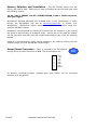
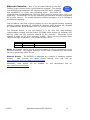
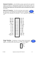
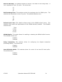
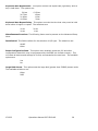
Power/Reset Connection – Power is supplied to the SAT-520Plus
through the 8-pin Molex connector at J13. The pin definitions are:
An optional momentary-contact, normally-open reset button can be connected
between pin 8 and ground.
Visual
Index

070223 Operations Manual SAT-520PLUS 4
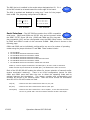
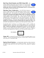
BIOS Extension Socket – The SAT-520Plus supports the use of
the Atmel 27C070 EPROM, or the Atmel 29C010 EEPROM to be used as
an extended BIOS for the user. Code for these parts must be offset
2000Hex bytes from the start of the prom. The 32-pin socket at U4 is used to contain
the Atmel devices used for the BIOS. The BIOS is memory mapped into a 8Kbyte hole
at segment D2000. An example jumpering for J3 with write enabled and disabled is
shown below.
Extension write enabled Extension write disabled
NOTE: The write enable/disable functions apply only to the Atmel 29C010 part.
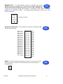
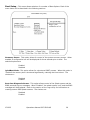
Floppy Disk Interface – The SAT-520Plus and the Phoenix BIOS
support up to two 5¼” or 3½” floppy disk drives. The drive types are
configured using the BIOS setup menus. The drives are connected via
the I/O connector at J5. Note that the interconnect cable to the drives is a standard
floppy I/O cable used on desktop PC’s. The cable must have the twisted section prior
to the drive A position. The pin definitions for the J5 connector are:
1 3 5 7 9 11 13
o o o o o o o
o o o o o o o
2 4
6 8 10 12 14
1 3 5 7 9 11 13
o o o o o o o
o o o o o o o
2 4 6 8 10 12 14
Visual
Index
1 o o 2
3 o o 4
5 o o 6
7 o o 8
9 o o 10
11 o o 12
13 o o 14
15 o o 16
17 o o 18
19 o o 20
21 o o 22
23 o o 24
25 o o 26
27 o o 28
29 o o 30
31 o o 32
33 o o 34
GND
GND
GND
GND
GND
GND
GND
GND
GND
GND
GND
GND
GND
GND
GND
GND
GND
RPM/LC
N/C
N/C
INDEX
MTR0
DRV1
DRV0
MTR1
DIR
STEP
WDATA
WGATE
TRK0
WPRT
RDATA
HDSEL
DSKCHG
Visual
Index

070223 Operations Manual SAT-520PLUS 5
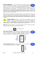
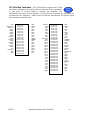
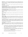
IDE Interface – The SAT-520Plus supports up to two IDE devices.
Connection to IDE hard disks and CD-ROMs is most easily
accomplished when using the WinSystems adapter cable, part number
CBL-126-9, connected to J6. This cable allows for the attachment of one standard 40-
pin IDE device. Configuration of any IDE device is accomplished using the Phoenix
BIOS setup menus.
The pin definitions for the 40-pin IDE
connector are:
DiskOnChip Configuration – The SAT-520Plus supports solid state disks using
the M-Systems DiskOnChip (DOC) flash devices (www.m-sys.com
). These devices are
available in sizes ranging from 8Mbytes to the currently available maximum size of
288Mbytes. These devices are inherently supported by the VIOS and DOS (they
appear as hard disk to DOS) and are supported by a variety of other operating
systems. Current non DOS driver support is available directly from the M-Systems
website.
The DOC device is ordinarily used in systems without an actual hard disk. In these
cases the hard drive settings for both the C: and D: drives should be set to NONE in
the CMOS Setup Menus. The DOC will then appear as drive C: and standard
partitioning and formatting software may be used to prepare it to boot. The boot-up
time may be dramatically improved by disabling the SC520 IDE controllers in the
CMOS setup when an actual hard disk will not be connected.
When the DOC is used in conjunction with an actual hard disk it automatically becomes
the secondary of D: drive. This can be useful when it is desired to load a DOC with a
large number of files that may currently reside on the hard disk. This characteristic of
becoming a secondary drive to an actual hard disk is referred to by M-Systems as
“Last Drive”. This characteristic may be altered such that the DOC will become the
primary drive (or First Drive) by using the DFORMAT utility available from M-Systems.
In this case it is possible to boot from the DOC and access the hard disk as the D:
drive. Refer to the utilities documentation accompanying the download from M-
Systems for more information if this mode is required.
1 o o 2
3 o o 4
5 o o 6
7 o o 8
9 o o 10
11 o o 12
13 o o 14
15 o o 16
17 o o 18
19 o o 20
21 o o 22
23 o o 24
25 o o 26
27 o o 28
29 o o 30
31 o o 32
33 o o 34
35 o o 36
37 o o 38
39 o o 40
RESET
D7
D6
D5
D4
D3
D2
D1
D0
GND
GND
IOW
IOR
N/C
N/C
INTRQ
A1
A0
HDCS0
N/C
GND
D8
D9D
10
C11
D12
D13
D14
D15
N/C
GND
GND
GND
ALE
GND
IOCS16
N/C
A2
HDCS1
GND
Visual
Index
An IDE Status LED, D1, provides visual status during IDE data transfer.

070223 Operations Manual SAT-520PLUS 6
The DOC device is installed in the socket-strips designated as U2. Pin 1
of the DOC should be oriented toward the outer edge of the board.
The DOC is enabled and disabled by using pins 7 and 8 of the jumper
block at J3. The jumpering configurations for J3 are:
DOC Enabled DOC Disabled
Serial Interface
– The SAT-520Plus contains four 16550 compatible
serial ports. COM3 and COM4 are RS-232 only and are present inside
the SMSC 37C727 Super I/O chip. COM3 and COM4 are fully plug-and-
play compatible (PnP) and are configurable using the BIOS setup menus. Connection
to COM3 and COM4 is made via the connector at J11. J11 pinout is shown on the
following page.
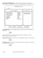
COM1 and COM2 can be individually configured for any one of a number of operating
modes using the jumper blocks at J7 and J10. These modes include:
1. RS-232 Mode
2. RS-422 Mode with RTS transmitter enable
3. RS-422 Mode with auto transmitter enable
4. RS-485 Mode with RTS transmitter enable
5. RS-485 Mode with RTS transmitter enable and echo back
6. RS-485 Mode with auto transmitter enable
7. RS-485 Mode with auto transmitter enable and echo back
Modes 2, 4 and 5 require the RTS bit in the MCR (Bit 1) be set in order to Transmit.
Modes 4 and 6 require that RTS in the MCR (Bit 1) be deasserted in order to receive.
Each of the RS-422/RS-485 modes also allows for jumper selection of transmit and/or
receive termination resistor(s). There is an 18-pin configuration jumper for both
COM1 and COM2 ports that allow the user to select the operating mode and its
optional features and termination. The jumper numbers and corresponding port
numbers are shown in the following table. There are three choices for termination
when RS-422 or RS-485 modes are used.
TX(100) - Places a 100 ohm resistor across the TX+/TX- pair.
RX(100) - Places a 100 ohm resistor across the RX+/RX- pair.
TX-RX(300) - Places a 100 ohm resistor from +5V to TX/RX+, a 100 ohm resistor from
TX-RX- to ground and a 100 ohm resistor between TX-RX+ and TX/RX-.
1 3 5 7 9 11 13
o o o o o o o
o o o o o o o
2 4 6 8 10 12 14
1 3 5 7 9 11 13
o o o o o o o
o o o o o o o
2 4 6 8 10 12 14
Visual
Index
Visual
Index

070223 Operations Manual SAT-520PLUS 7
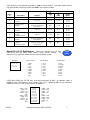
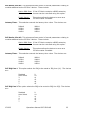
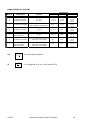
Each channel is configured using J7 or J10 as shown above. The table below shows
the appropriate jumpering for J7 and J10 in the various modes.
Termination
Mode
# Description Jumpers
TX
(100
)
RX
(100)
TX/RX
(300)
1 RS-232 1-2 N/A N/A N/A
2
RS-422 RTS
Enable
3-4, 9-10 11-12 17-18
11-12
13-14
15-16
3
RS-422 Auto
Enable
3-5, 9-10 (One node
must use TX/RX 300
Termination)
N/A 17-18
11-12
13-14
15-16
4
RS-485 RTS
Enable
3-4, 7-8 11-12 N/A
11-12
13-14
15-16
5
RS-485 RTS
Enable
with Echo-Back
3-4, 8-6 11-12 N/A
11-12
13-14
15-16
6
RS-485 Auto
Enable
3-5, 7-8 (One node
must use TX/RX 300
Termination)
N/A N/A
11-12
13-14
15-16
7
RS-485 Auto
Enable
with Echo-Back
3-5, 8-6 (One node
must use TX/RX 300
Termination)
N/A N/A
11-12
13-14
15-16
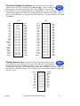
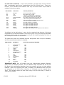
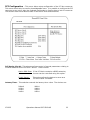
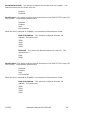
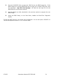
Serial Port I/O Definitions – Serial port definitions for all four
COM ports are the same when used in their various modes. Pin
definitions for each are shown below in each possible mode.
DB9 Male
COM3 and COM4 are RS-232 only and are terminated at J11. An adapter cable is
available from WinSystems, part number CBL-173-1, adapting J11 to two standard
DB9M connectors. The pin definitions for J11 are:
1 o o 2
3 o o 4
5 o o 6
7 o o 8
9 o o 10
11 o o 12
13 o o 14
15 o o 16
17 o o 18
19 o o 20
COM3 – DCD
COM3 – RX
COM3 – TX
COM3 – DTR
GND
COM4 – DCD
COM4 – RX
COM4 – TX
COM4 – DTR
GND
COM3 – DSR
COM3 – RTS
COM3 – CTS
COM3 – RI
N/C
COM4 – DSR
COM4 – RTS
COM4 – CTS
COM4 – RI
N/C
1 2 3 4 5
o o o o o
o o o o
6 7 8 9
RS-232 Mode
1. DCD
2. RX
3. TX
4. DTR
5. GND
6. DSR
7. RTS
8. CTS
9. RI
RS-422 Mode
1. N/A
2. TX+
3. TX+
4. N/A
5. GND
6. RX+
7. RX-
8. N/A
9. N/A
RS-485 Mode
1. N/A
2. TX/RX+
3. TX/RX-
4. N/A
5. GND
6. N/A
7. N/A
8. N/A
9. N/A
Visual
Index

070223 Operations Manual SAT-520PLUS 8
Ethernet Controller – One of the principal features of the SAT-
520Plus is the inclusion of the 10/100 Ethernet controller. The popular
Intel 82551ER high-integration NIC supports both IEEE 802.3 10BASE-T
and 100BASE-TX in a fully auto-negotiating mode. The 82551 ER
integrates both the Media Access Controller (MAC) and the physical layer (PHY) on a
single chip. The 82551ER is a full bus mastering PCI controller and also incorporates
6K of buffer memory. Full duplex operation provides throughput of up to 200Mbs of
fast Ethernet segments.
Intel provides a vast array of driver support for all of the popular network operating
systems including: Windows CE, Windows 95, Windows 98SE, Windows ME, Windows
NT, Windows 2000, Novell Netware 3.11-4.1, Solaris, Linux, and Unix.
The Ethernet section of the SAT-520Plus is a full PCO PnP (plug-and-play)
implementation coupled with the Phoenix PCI BIOS which assigns the necessary I/O,
Memory, DMA, and IRQ resources required by the controller. Connection to the
network is made via the RJ-45 connector at J17. There are three Ethernet status
LEDs on the edge of the board. The purpose of each LED is:
NOTE: WinSystems cannot provide technical support for direct programming of the
82551ER controller. We suggest utilizing a TCP/IP stack of Network O/S that allows
the use of preexisting 82551 drivers.
Ethernet Drivers – The 82551ER is supported by a number of operating systems
directly. Intel provides the latest drivers through their web site at:
http://developer.intel.com/design/network/drivers/
Alternately, most drivers will be available for the WinSystems site at:
http://www.winsystems.com
D10 (YELLOW) LINK ACTIVE
D9 (RED) SPEED INDICATION – LIT=100BASE-TX
D8 (GREEN) ACTIVITY
Visual
Index

070223 Operations Manual SAT-520PLUS 9
1 2
o o
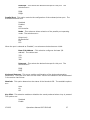
Parallel I/O – The SAT-520Plus contains an 82C55A type device
supporting 24 lines of digital I/O. These 24 lines are terminated at J8,
and are enabled and disabled using pins 13 and 14 of J3. When J3 pins
13 and 14 are jumpered, digital I/O is enabled. An example is shown below. The base
address of the 82C55A is 1E8H. For programming information, refer to the Intel
82C55A Datasheet.
Parallel I/O Connector – The parallel I/O connector is located at J8.
The pin definitions are:
NOTE: Pin 49 of J8 may be configured to supply +5 volts to pin 49 by
placing a jumper on J1. The current draw from pin 49 should not
exceed 300mA.
1 o o 2
3 o o 4
5 o o 6
7 o o 8
9 o o 10
11 o o 12
13 o o 14
Parallel I/O enabled
1 o o 2
3 o o 4
5 o o 6
7 o o 8
9 o o 10
11 o o 12
13 o o 14
15 o o 16
17 o o 18
19 o o 20
21 o o 22
23 o o 24
25 o o 26
27 o o 28
29 o o 30
31 o o 32
33 o o 34
35 o o 36
37 o o 38
39 o o 40
41 o o 42
43 o o 44
45 o o 46
47 o o 48
49 o o 50
PORT C BIT 7
PORT C BIT 6
PORT C BIT 5
PORT C BIT 4
PORT C BIT 3
PORT C BIT 2
PORT C BIT 1
PORT C BIT 0
PORT B BIT 7
PORT B BIT 6
PORT B BIT 5
PORT B BIT 4
PORT B BIT 3
PORT B BIT 2
PORT B BIT 1
PORT B BIT 0
PORT A BIT 7
PORT A BIT 6
PORT A BIT 5
PORT A BIT 4
PORT A BIT 3
PORT A BIT 2
PORT A BIT 1
PORT A BIT 0
+5V
GND
GND
GND
GND
GND
GND
GND
GND
GND
GND
GND
GND
GND
GND
GND
GND
GND
GND
GND
GND
GND
GND
GND
GND
GND
Visual
Index
Visual
Index
Visual
Index

070223 Operations Manual SAT-520PLUS 10
VGA Configuration – The SAT-520Plus uses a fourth generation
CRT/Flat panel Super VGA controller. It supports standard VGA output
as well as a variety of Flat Panel Displays using optional Flat Panel
Adapter (FPA) kits. The video on the SAT-520Plus uses the Asiliant 69000 series of
high performance VGA controllers. The Asiliant controller supports standard and
Super-VGA as well as color and monochrome panels with 8, 9, 12, 15, 16, 18, 24 and
36-bit interfaces. WinSystems provides flat panel support through a series of Flat
Panel kits. Contact your WinSystems’ Applications Engineer for the most current list of
available FPAs and supported panels.
Details regarding interfacing to specific Flat Panels is not provided in this manual but
should be referenced in the documentation accompanying the FPA kit. Attempted
connection to any flat panel not directly supported by a WinSystems’ FPA module is at
the user’s risk and extreme care should be exercised to avoid damaging or destroying
the panel.
HAZARD WARING: LCD panels can require a high voltage for the panel
backlight. This high-frequency voltage can exceed 1000 volts and can
present a shock hazard. Care should be taken when wiring or handling the
inverter output. To avoid danger of shock and to avoid damaging fragile and
expensive panels, make all connection changes with power removed.
NOTE: J12 must be jumpered 1-2 for Sharp type panels, and 2-3 for NEC type panels.
An example jumpering for NEC panels is shown below.
CRT Output Connection – Video output to a standard VGA monitor is
made via the connector at J15. An adapter cable, part number CBL-
234-1, is available from WinSystems to adapt from J15 to the standard
DB15 VGA connector. The pin definitions for the J15 connector are:
Panel Backlight Connection – Panel Backlight connection is made via
the connector at J18. The pinout for J18 is:
1 2 3
o o o
Panel Backlight Enable
1 o o 2
3 o o 4
5 o o 6
7 o o 8
9 o o 10
11 o o 12
13 o o 14
GND
GND
GND
GND
GND
GND
VCC
RED
GREEN
BLUE
HSYNC
VSYNC
DDCDATA
DDCCLK
o 1
o 2
o 3
o 4
o 5
o 6
o 7
+12
+12
GND
GND
ENBKL
VCC
VCC
Visual
Index
Visual
Index
Visual
Index

070223 Operations Manual SAT-520PLUS 11
Flat Panel Output Connection – Connection to all flat panels is
made via the two 50-pin connectors at J19 and J20. These connectors
are cabled to the appropriate FPA (Flat Panel Adapter) module which
then breaks out the necessary cabling for attachment to the panel itself. The FPA
module also supplies any special controls that may be needed for the panel. Refer to
the FPA documentation for specific hook-up instructions. The pin definitions for J19
and J20 are:
J19 J20
Parallel Printer Port – The SAT-520Plus supports a parallel printer
port contained in the SMSC37C727 super I/O chip and is terminated at
the Multi-I/O connector at J9. This port is fully PnP compatible and is
configurable using the Phoenix BIOS setup menus. The parallel port can be configured
for SPP, EPP and ECP modes. The pin definitions for the DB25 connecter using the
CBL-247-1 are:
1 o o 2
3 o o 4
5 o o 6
7 o o 8
9 o o 10
11 o o 12
13 o o 14
15 o o 16
17 o o 18
19 o o 20
21 o o 22
23 o o 24
25 o o 26
27 o o 28
29 o o 30
31 o o 32
33 o o 34
35 o o 36
37 o o 38
39 o o 40
41 o o 42
43 o o 44
45 o o 46
47 o o 48
49 o o 50
SW0
SW2
FP0
FP1
FP2
FP3
FP4
FP5
FP6
FP7
FP8
FP9
FP10
FP11
PCSHCLK
PCFLM
PCLP
PCM
PHSYNC
PVSYNC
ENVCC
ENBKL
ENVEE
+12V
SWVCC
SW1
SW3
GND
GND
GND
GND
GND
GND
GND
GND
GND
GND
GND
GND
GND
GND
GND
GND
GND
GND
GND
GND
-12V
+12V
SWVCC
1 o o 2
3 o o 4
5 o o 6
7 o o 8
9 o o 10
11 o o 12
13 o o 14
15 o o 16
17 o o 18
19 o o 20
21 o o 22
23 o o 24
25 o o 26
27 o o 28
29 o o 30
31 o o 32
33 o o 34
35 o o 36
37 o o 38
39 o o 40
41 o o 42
43 o o 44
45 o o 46
47 o o 48
49 o o 50
FP12
FP13
FP14
FP15
FP16
FP17
FP18
FP19
FP20
FP21
FP22
FP23
FP24
FP25
FP26
FP27
FP28
FP29
FP30
FP31
FP32
FP33
FP34
FP35
SWVCC
GND
GND
GND
GND
GND
GND
GND
GND
GND
GND
GND
GND
GND
GND
GND
GND
GND
GND
GND
GND
GND
GND
GND
GND
SWVCC
Visual
Index
1 o o 14
2 o o 15
3 o o 16
4 o o 17
5 o o 18
6 o o 19
7 o o 20
8 o o 21
9 o o 22
10 o o 23
11 o o 24
12 o o 25
13 o
STROBE
PD0
PD1
PD2
PD3
PD4
PD5
PD6
PD7
ACK
BUSY
PE
SLCT
AUTOFD
ERROR
INIT
SLIN
GND
GND
GND
GND
GND
GND
GND
GND
Visual
Index

070223 Operations Manual SAT-520PLUS 12
1 o
2 o
3 o
4 o
5 o
MSDATA
N/C
GND
VCC
MSCLK
1 o o 2
3 o o 4
5 o o 6
7 o o 8
9 o o 10
11 o o 12
13 o o 14
15 o o 16
17 o o 18
19 o o 20
21 o o 22
23 o o 24
25 o o 26
27 o o 28
29 o o 30
31 o o 32
33 o o 34
35 o o 36
37 o o 38
39 o o 40
41 o o 42
43 o o 44
45 o o 46
47 o o 48
49 o o 50
COM1 - DCD
COM1 - RXD
COM1 - TXD
COM1 - DTR
COM1 - GND
COM2 - DSR
COM2 - RTS
COM2 - CTC
COM2 - RI
LPT - STROBE
LPT - PD0
LPT - PD1
LPT - PD2
LPT - PD3
LPT - PD4
LPT - PD5
LPT - PD6
LPT - PD7
LPT - ACK
LPT - BZY
LPT - PE
LPT - SLCT
KEYBD - GND
KEYBD - KDATA
KEYBD - +5V
COM1 - DSR
COM1 - RTS
COM1 - CTC
COM1 - RI
COM2 - DCD
COM2 - RSX
COM2 - TXD
COM2 - DTR
COM2 - GND
LPT - AUTOFD
LPT - ERROR
LPT - INIT
LPT - SLCTIN
LPT - GND
LPT - GND
LPT - GND
LPT - GND
LPT - GND
LPT - GND
LPT - GND
LPT - GND
KEYBD - GND
KEYBD - GND
KEYBD - CLK
KEYBD - +5V
Keyboard Interface – The SAT-520Plus contains onboard PS/2 style keyboard
controller. Connection is made through the Multi-I/O cable connection at J9. An
adapter cable, CBL-247-1 is available from WinSystems to make ready access to all of
the devices terminated at the Multi-I/O connector. Users who may wish to construct
their own cables should refer to the Multi-I/O connector pin definitions given later in
this manual.
Multi-I/O Connector – The I/O to the primary serial channels,
the printer port, and keyboard are all terminated via the connector at
J9. WinSystems’ multi-I/O cable, part number CBL-247-1, is available
to adapt to the conventional I/O connectors. The pin definitions for J9 are shown
here:
Mouse Interface – Connection to a mouse is made via the connector
at J14. An adapter cable, CBL-225-1, is available from WinSystems to
adapt to a conventional PS/2 mouse connector. The pinout for J14 is:
Visual
Index
Visual
Index

070223 Operations Manual SAT-520PLUS 13
Real-Time Clock/Calendar and CMOS Setup RAM – The
onboard 350mAH lithium battery provides power to the real-time clock
and the CMOS setup RAM when power is removed. If it ever becomes
necessary to have the CMOS RAM settings return to their default factory
settings, with power off, reposition the J3 jumper from pins 1-2 to pins 2-4 for
approximately 30 seconds and then return the jumper to pins 1-2. At the next power-
up the BIOS will load the factory defaults.
Watchdog Timer Configuration – The SAT-520Plus features a
power-on voltage detect and a power-down/power brownout circuit to
protect memory and I/O from faulty CPU operation during periods of
illegal voltage levels. This supervisory circuit also features a watchdog
timer which can be used to guard against software lockups. An internal self-timer with
a period of 1/5 second will, when enabled, reset the CPU if the watchdog has not been
serviced (petted) within the allotted time. There are three watchdog operational
modes available on the SAT-520Plus. With a jumper placed on pins 5-6 of J3, the
watchdog circuit is totally disabled and can never reset the processor. When J3 pins
are not jumpered, the watchdog timer is permanently enabled and timing begins
immediately at power up. This mode is NOT compatible with the Phoenix BIOS or with
MS-DOS but is available for directly embedded code that replaces the BIOS. The
watchdog must be accessed at least every 1.5 seconds or a reset will occur. Petting in
this mode is accomplished with a single I/O write (value ignored) to address 1EFH.
The alternate mode of operation is via software control to enable or disable the
watchdog’s operation. This mode is set by jumpering J3 pins 3-5. In this mode the
watchdog powers-up disabled and must be enabled in software before timing will
begin. Enabling the watchdog is accomplished by writing a 1 to I/O port 1EEH.
Writing a 0 to I/O address 1EEH will disable the watchdog. Once the watchdog is
enabled, it must be serviced at least every 1.5 seconds or a rest will occur. Petting in
this mode is accomplished with a single I/O write (value ignored) to address 1EFH.
Status LED – An onboard LED can be used by software for signaling status or error
conditions, The LED is illuminated by writing a 1 to I/O port 1EDH. The LED is turned
off by writing a 0 to I/O address 1EDH.
Speaker/Sound Interface - An onboard audio transducer provides a high level
audio output which is compatible with the standard PC speaker. This output is used by
the BIOS to signal POST errors and may be used by user software for signaling
purposes.
Visual
Index
Visual
Index
J3 orientation
1 3 5 7 9 11 13
o o o o o o o
o o o o o o o
2 4 6 8 10 12 14

070223 Operations Manual SAT-520PLUS 14
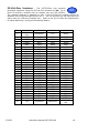
PC/104 Bus Interface – The SAT-520Plus supports the PC/104
bus which is basically the original ISA bus with the 16-bit extensions.
A vast array of PC/104 stack-on modules are available from
WinSystems and other PC/104 suppliers. The PC/104 bus connector pin definitions are
provided here for reference. Refer to the PC/104 Bus Specification for specific signal
and mechanical specifications.
A1 o o B1
A2 o o B2
A3 o o B3
A4 o o B4
A5 o o B5
A6 o o B6
A7 o o B7
A8 o o B8
A9 o o B9
A10 o o B10
A11 o o B11
A12 o o B12
A13 o o B13
A14 o o B14
A15 o o B15
A16 o o B16
A17 o o B17
A18 o o B18
A19 o o B19
A20 o o B20
A21 o o B21
A22 o o B22
A23 o o B23
A24 o o B24
A25 o o B25
A26 o o B26
A27 o o B27
A28 o o B28
A29 o o B29
A30 o o B30
A31 o o B31
A32 o o B32
GND
RESET
+5V
IRQ9
-5V
DRQ2
-12V
SRDY
+12V
KEY
SMEMW*
SMEMR*
IOW*
IOR*
DACK3*
DRQ3
DACK1*
DRQ1
REFRESCH*
BCLK
IRQ7
IRQ6
IRQ5
IRQ4
IRQ3
DACK2*
T/C
BALE
+5V1
OSC
GND
GND
IOCHK*
SD7
SD6
SD5
SD4
SD3
SD2
SD1
SD0
IOCHRDY
AEN
SA19
SA18
SA17
SA16
SA15
SA14
SA13
SA12
SA11
SA10
SA9
SA8
SA7
SA6
SA5
SA4
SA3
SA2
SA1
SA0
GND
D0 o o C0
D1 o o C1
D2 o o C2
D3 o o C3
D4 o o C4
D5 o o C5
D6 o o C6
D7 o o C7
D8 o o C8
D9 o o C9
D10 o o C10
D11 o o C11
D12 o o C12
D13 o o C13
D14 o o C14
D15 o o C15
D16 o o C16
D17 o o C17
D18 o o C18
D19 o o C19
GND
SBHE*
LA23
LA22
LA21
LA20
LA19
LA18
LA17
MEMR*
MEMW*
SD8
SD9
SD10
SD11
SD12
SD13
SD14
SD15
KEY
GND
MEMCS16*
IOCS16*
IRQ10
IRQ11
IRQ12
IRQ15
IRQ14
DACK0*
DRQ0
DACK5*
DRQ5
DACK6*
DRQ6
DACK7*
DRQ7
+5V
MASTER*
GND
GND
Visual
Index
Page is loading ...
Page is loading ...
Page is loading ...
Page is loading ...
Page is loading ...
Page is loading ...
Page is loading ...
Page is loading ...
Page is loading ...
Page is loading ...
Page is loading ...
Page is loading ...
Page is loading ...
Page is loading ...
Page is loading ...
Page is loading ...
Page is loading ...
Page is loading ...
Page is loading ...
Page is loading ...
Page is loading ...
Page is loading ...
Page is loading ...
Page is loading ...
Page is loading ...
Page is loading ...
Page is loading ...
Page is loading ...
Page is loading ...
Page is loading ...
-
 1
1
-
 2
2
-
 3
3
-
 4
4
-
 5
5
-
 6
6
-
 7
7
-
 8
8
-
 9
9
-
 10
10
-
 11
11
-
 12
12
-
 13
13
-
 14
14
-
 15
15
-
 16
16
-
 17
17
-
 18
18
-
 19
19
-
 20
20
-
 21
21
-
 22
22
-
 23
23
-
 24
24
-
 25
25
-
 26
26
-
 27
27
-
 28
28
-
 29
29
-
 30
30
-
 31
31
-
 32
32
-
 33
33
-
 34
34
-
 35
35
-
 36
36
-
 37
37
-
 38
38
-
 39
39
-
 40
40
-
 41
41
-
 42
42
-
 43
43
-
 44
44
-
 45
45
-
 46
46
-
 47
47
-
 48
48
-
 49
49
-
 50
50


WinSystems SAT-520PLUS Operating instructions
- Category
- Interface cards/adapters
- Type
- Operating instructions
Ask a question and I''ll find the answer in the document
Finding information in a document is now easier with AI
Related papers
-
WinSystems LPM-LX800 User manual
-
-
-
-
-
-
-
WinSystems PCM-J1708 Operating instructions
-
-
Other documents
-
Brainboxes IX-500 Datasheet
-
Advantech PCM-3641P Startup Manual
-
Eurotech CPU-1421 Owner's manual
-
Manhattan 158237 Datasheet
-
-
Lava Computer 16550 UARTs User manual
-
Contec GP-IB(PC)L Owner's manual
-
-
Quatech SPP-100 Datasheet
-
 INTAMSYS SP10 10.1 Inch Android Industrial Panel Computer Operating instructions
