
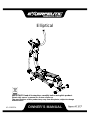
OWNER’S MANUAL
Elliptical
IMPORTANT: Read all instructions carefully before using this product.
Retain this owner’s manual for future reference.
The specifications of this product may vary from this photo, subject to change
without notice.
V1.0-050714

SERVICE ------------------------------------------------------------------------ 2
LABEL PLACEMENT --------------------------------------------------------- 3
PRODUCT SAFETY ---------------------------------------------------------- 4
OVERVIEW DRAWING ------------------------------------------------------ 5
PARTS LIST --------------------------------------------------------------------- 6
HARDWARE LIST & TOOLS ----------------------------------------------- 9
ASSEMBLY ---------------------------------------------------------------------- 10
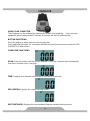
COMPUTER --------------------------------------------------------------------- 23
ADJUSTMENT ----------------------------------------------------------------- 25
TROUBLE SHOOTING & MAINTENANCE ----------------------------- 26
WARM UP ---------------------------------------------------------------------- 27
WARRANTY -------------------------------------------------------------------- 28
FAX FORM ---------------------------------------------------------------------- 29
1
TABLE OF CONTENTS

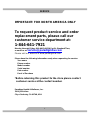
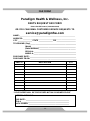
IMPORTANT: FOR NORTH AMERICA ONLY
To request product service and order
replacement parts, please call our
customer service department at:
1-844-641-7921
Monday through Friday, 8:00 AM-5:00 PM Pacific Standard Time,
or email us at: service@paradigmhw.com
Please visit our website at www.paradigmhw.com.
Please have the following information ready when requesting for service:
Your name
Phone number
Model number
Serial number
Part number
Proof of Purchase
*Before returning this product to the store please contact
customer service at the contact number.
Paradigm Health & Wellness, Inc.
1189 Jellick Ave.
City of Industry, CA 91748, USA
SERVICE
2

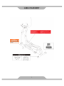
3
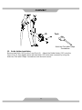
LABEL PLACEMENT

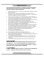
Basic precautions should always be followed, including the following
Important safety instructions when using this equipment. Read all
instructions before using this equipment.
1. Read all the instructions in this manual and do warm up exercises before
using this product.
2. Before exercise, in order to avoid injuring your muscles, warm-up
exercise for every muscle group is highly recommended. Please refer to
the Warm Up pages for pre and post workout.
3. Please make sure all parts are not damaged and functioning before use.
This product should be placed on a flat surface when using. Using a mat
or other covering material on the ground is recommended.
4. Please wear proper clothes and shoes when using this equipment; do not
wear clothes that might catch any part of the equipment.
5. Do not attempt any maintenance or adjustments other than those
described in this manual. Should any problems arise, discontinue use
and consult an Authorized Service Representative.
6. Be careful when stepping on or leaving the pedals. Make sure to hold on
to the handlebars when mounting and dismounting. When mounting,
make sure the pedal is at its lowest point before you step on. While in
use, please onto the handlebars and use both the pedals and the
handlebars in tandem to insure a smooth, effective workout.
7. Do not use the product outdoors.
8. This product is for household use only.
9. Only one person should be on the product while in use.
10. Keep children and pets away from the product while in use. This
machine is designed for adults only. This product requires a minimum of
6 feet of space for safe operation.
11. If you feel any chest pains, nausea, dizziness, or short of breath, you
should stop exercising immediately and consult your physician before
continuing.
12. The maximum weight capacity for this product is 270 lbs/122.6 kgs.
WARNING: Before beginning any exercise program consult
your physician. This is especially important for the people who are
over 35 years old or who have pre-existing health problems. Read all
instructions before using any fitness equipment.
CAUTION: Read all instructions carefully before operating this
product. Retain this Owner’s Manual for future reference.
PRODUCT SAFETY
4

OVERVIEW DRAWING
5

No.
Description
Qty
No.
Description
Qty
001
Main Frame
1
022L
Left Foot Pedal
1
002
Front Stabilizer Ø60x1.5tx510mm
1
022R
Right Foot Pedal
1
003
Rear Stabilizer Ø60x1.5tx590mm
1
023A
Lower Crank Cover A (Black)
2
004
Front Post Ø60x2.0tx975mm
1
023B
Lower Crank Cover B (Black)
2
005
Handlebar Ø32
1
024
Belt Pulley Ø220
1
006L
Upper Left Handrail Ø32
1
025
Belt Pulley Ø180
1
006R
Upper Right Handrail Ø32
1
026
Handrail Foam Grip
Ø32x5tx750mm
2
007L
Left Handrail Arm Ø32
1
027
Handlebar Foam Grip
Ø32x3tx380mm
2
007R
Right Handrail Arm Ø32
1
028
Flywheel Ø200
1
008
U Shape Bracket
2
029
Magnet Bracket
1
009L
Left Foot Bar
1
030
Handlebar End Cap Ø32
2
009R
Right Foot Bar
1
031
Handrail End Cap Ø50
2
010
Crank
2
032
Hexagon Socket Head Bolt
M8x15mm
2
011
Computer
1
033
Hexagon Socket Head Bolt
M8x15mm
8
012
Computer Wire L=1050mm
1
034
Carriage Bolt M8x70mm
4
013
Tension Control
1
035
Cap Nut M8
4
014
Tension Control Cable
1
036
Washer Ø8xØ16x1.5T
8
015
Extension Sensor Wire
L=1250mm
1
037
Belt Pulley Shaft Ø12x90mm
1
016
Hand Pulse Sensor
2
038
Curve Washer Ø21xØ8x2t
10
017
Hand Pulse Sensor Wire
L=600mm
2
039
Hexagon Socket Head Bolt
M8x42mm
4
018
Washer Ø8xØ38x2.0T
2
040
Nylon Locknut M8
7
019
Front Stabilizer End Cap Ø60
2
041
Hexagon Socket Head Bolt
M10x80mm
2
020
Rear Stabilizer End Cap Ø60
2
042
Washer Ø10xØ19x1.5t
3
021L
Left Cover
1
043
Carriage Bolt M6x45mm
4
021R
Right Cover
1
044
Nylon Locknut M10
4
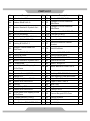
PARTS LIST
6

No.
Description
Qty
No.
Description
Qty
045
Nylon Locknut M6
4
071
Washer Ø8xØ25x2.0T
2
046
Washer Ø6xØ14x1.0t
6
072
Hexagon Socket Head Bolt
M8x54mm
2
047
Tension Bracket & Eyebolt Set I
2
073
Hexagon Socket Head Bolt
M8x50mm
1
048
Washer Ø10xØ20x3.0T
6
074
Hexagon Head Bolt M10x32
1
049
Nut 3/8"x26tx6mm
4
075A
Foot Bar Cover-A
2
050
Plastic Bushing Ø19xØ38x64mm
2
075B
Foot Bar Cover-B
2
051
Washer Ø19.5xØ38x0.5T
2
076
Nylon Nut M5
2
052
Bushing Ø10x32x2.5
4
077
Bolt M5x12mm for Sensor
Bracket
1
053
Hexagon Socket Head Bolt
M8x18mm
4
078
Bolt M5x60mm
1
054
Bushing Ø16.3x22.4
4
079
Washer Ø12xØ17x1.0T
1
055
Bushing Ø19x38
4
080
Spring Washer 8mm
8
056
Bolt M6x12
2
081
Washer Ø10xØ16x1.5T
1
057
Tension Bracket & Eyebolt Set II
2
082
Spacer Ø10x15x9
2
058
U shape plate
1
083
Inner C Ring Ø12
2
059
Round Head Self Tapping Screw
M4.5x15mm
14
084
Wave Washer Ø12xØ17x0.2t
1
060
Decorate Cover Ø60
1
085
Conical Washer Ø8.15xØ11x3.5
4
061
Decorate Cover □30x60
1
086
Bushing Ø12xØ18x11.5
4
062
Bearing R12
2
087
Self-Tapping Screw M4x20mm
2
063
Self-Tapping Screw M5x15mm
4
088A
Upper Crank Cover A
2
064
Washer Ø19.5xØ25x2.0T
1
088B
Upper Crank Cover B
2
065
Nut M10
2
089
Wire Plug
1
066
Inner C Ring Ø19
1
090
Magnet
8
067
Washer Ø19.5xØ25x3.0T
1
091
Spring 0.8x13
1
068
Round Head Self Tapping Screw
M4.5x25mm
5
092
Sensor Magnet Ø15x7mm
1
069A
U Shape Bracket Cover A
2
093
Sensor Bracket
1
069B
U Shape Bracket Cover B
2
094
Belt 320J4
1
070
Wave Washer Ø16.2xØ25x0.5t
2
095
Belt 340J6
1
7
PARTS LIST

No.
Description
Qty
No.
Description
Qty
096
Idle Wheel 10x36x22
2
101
Bottle Holder
1
097
Spring 2.6x8
1
102
Bolt M5x15mm
2
098
Idle wheel fixture
1
103
Bolt for Computer
4
099
Hexagon Socket Head Bolt
M10x20mm
1
Multi Hex Tool with Phillips
Screwdriver 10x14x17mm
1
100
Carriage Bolt M10x35mm
1
Allen Wrench 5mm
1
8
PARTS LIST

9
(#36) Washer
8 PCS
(#39) Hexagon Socket
Head Bolt
4 PCS
(#40) Nylon Locknut
7 PCS
(#43) Carriage Bolt
4 PCS
(#45) Nylon Locknut
4 PCS
(#46) Washer
6 PCS
(#51) Washer
2 PCS
(#53) Hexagon Socket
Head Bolt
4 PCS
(#70) Wave Washer
2 PCS
(#71) Washer
2 PCS
Multi Hex Tool with
Phillips Screwdriver
1 PC
Allen Wrench
1 PC
(#18) Washer
2 PCS
(#34) Carriage Bolt
4 PCS
(#35) Cap Nut M8
4 PCS
(#59) Round Head Self
Tapping Screw
14 PCS
(#41) Hexagon Socket
Head Bolt
2 PCS
(#42) Washer
3 PCS
(#44) Nylon Locknut
4 PCS
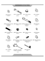
HARDWARE LIST & TOOLS

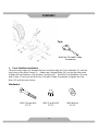
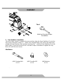
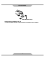
1. Front Stabilizer Installation.
Lift up the main frame (1) towards the front, and then align the Front Stabilizer (2) onto the
front curve of the Main Frame (1). Attach two Carriage Bolts (34) and on the other ends
of bolts with two Washers (36) and two Cap Nuts (35). Hold the Front Stabilizer (2) to the
Main Frame (1) and use the Multi Hex Tool with Phillips Screwdriver to tighten the Cap
Nuts (35) until firm and secure.
Hardware:
ASSEMBLY
10
(#36) Washer
2 PCS
(#34) Carriage Bolt
2 PCS
(#35) Cap Nut M8
2 PCS
Tool:
Multi Hex Tool with Phillips
Screwdriver

2. Rear Stabilizer Installation.
Lift up the Main Frame (1) towards the end, and then align the Rear Stabilizer (3) onto the
rear curve of the Main Frame (1). Attach Two Carriage Bolts (34) and on the other ends
of bolts with two Washers (36) and two Cap Nuts (35). Hold the Rear Stabilizer (3) to the
Main Frame (1) and use the Multi Hex Tool with Phillips Screwdriver to tighten the Cap
Nuts (35) until firm and secure.
Hardware:
.
ASSEMBLY
11
(#36) Washer
2 PCS
(#34) Carriage Bolt
2 PCS
(#35) Cap Nut M8
2 PCS
Tool:
Multi Hex Tool with Phillips
Screwdriver

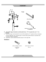
3. Assemble Handlebar.
A. Use Allen Wrench to remove two Hexagon Socket Head Bolts (32) and two Curve
Washers (38) from the Front Post (4).
Take off the Wire Plug (89) from the right hand side of the Front Post (4).
B. Put Hand Pulse Sensor Wires (17) from the Handlebar (5) through the Wire Plug (89).
Then insert the wires into the hole located on the right hand side of the Front Post (4).
Pull the Hand Pulse Sensor Wires (17) from the top end of the Front Post (4). Attach the
Wire Plug (89) back to the Front Post (4).
C. Attach the Handlebar (5) on top of the Front Post (4), and then tighten the two Hexagon
Socket Head Bolts (32) and two Curve Washers (38) by Allen Wrench. Make sure it’s
firm and secure.
12
ASSEMBLY
Allen Wrench
Tool:

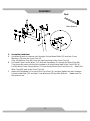
4. Computer Installation
Connect the Hand Pulse Sensor Wires (17) and Extension Sensor Wire (12) to the wires
that come from the Computer (11). Tuck wires into the Handlebar Post (4). Attach the
Computer (11) onto the top end of the Handlebar Post (4) with four Cross Recessed Pan
Head Bolts (103) that were removed.
Use the Multi Hex Tool with Phillips Screwdriver to tighten the Cross Recessed Pan Head
Bolts (103) until firm and secure.
13
ASSEMBLY
Multi Hex Tool with Phillips
Screwdriver
Tool:

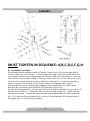
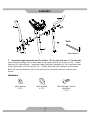
MUST TIGHTEN IN SEQUENCE: A,B,C,D,E,F,G,H.
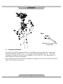
5. Assemble Front Post.
Put the cable end of resistance cable of Tension Control Knob (13) into the cable lock of
Tension Cable (14), see Figure A. Pull the resistance cable of Tension Control Knob (13)
up and force it into the slot of metal bracket of Tension Cable (14), see Figure B. Insert the
metal fitting on the resistance cable of Tension Control Knob (13) into the hole at the end of
the slot in the metal bracket of Tension Cable (14), see Figure C. Connect the resistance
cable of Tension Control Knob (13) to Tension Cable (14) complete, see Figure D.
Use the Allen Wrench to remove eight Hexagon Socket Head Bolts (33), eight Spring
Washers (80), and eight Curve Washers (38) from the Front Post (4).
Connect the Computer Wire (12) from the Front Post (4) with the Extension Sensor Wire (15)
from the Main Frame (1). Insert the Front Post (4) into Main Frame (1). Make sure the
wire stay connected. Tighten the eight Hexagon Socket Head Bolts (33) which start with
A,B,C & D first, four Spring Washers (80), and four Curve Washers (38) by Allen Wrench,
then tighten E,F, G &H as same procedure.
ASSEMBLY
14

6. Assemble Upper Handrails and Handrail Arms: “R” for right side and “L” for
left side.
A. Insert the Upper Left Handrail (6L) into Left Handrail Arm (7L), tighten with two Hexagon
Socket Head Bolts (39) and two Nylon Locknuts (40) by Allen Wrench and Multi Hex
Tool with Phillips Screwdriver.
B. Repeat the same Handrail assembly steps for the right side.
Hardware:
15
ASSEMBLY
(#39) Hexagon Socket
Head Bolt
4 PCS
(#40) Nylon Locknut
4 PCS
Allen Wrench
Tool:
Multi Hex Tool with Phillips
Screwdriver

7. Assemble Upper Handrails and Front Post: “R” for right side and “L” for left side.
Insert Plastic Bushings (50) on both sides of the central axis on the Front Post (4). Attach
Washers (51) behind them. Insert the Upper Left/Right Handrails (6L, 6R) onto both sides
of the central axis on the Front Post (4). Tighten them with two Hexagon Socket Head
Bolts (53) and two Washers (18) to the front post by using Allen Wrench until firm and
secure.
Hardware:
16
6
ASSEMBLY
(#51) Washer
2 PCS
(#18) Washer
2 PCS
(#53) Hexagon Socket
Head Bolt
2 PCS
Allen Wrench
Tool:

–––-
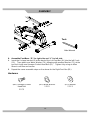
8. Assemble Foot Pedals: “R” for right side and “L” for left side.
A. Place the Left Foot Pedal (22L) on top of the Left Foot Bar (9L), align to the bolt hole
with two Carriage Bolts (43) two Washes (46) and two Nylon Locknuts (45) by using
Multi Hex Tool with Phillips Screwdriver.
B. Repeat the same assembly steps to the Right Foot Bar (9R).
Note: There are four holes on the Left/Right Foot Bars (9L, 9R) for personal foot pedal
adjustment use.
Hardware:
17
(#43) Carriage Bolt
4 PCS
(#45) Nylon Locknut
4 PCS
(#46) Washer
4 PCS
ASSEMBLY
Tool:
Multi Hex Tool with Phillips
Screwdriver

9. Assemble Foot Bars: “R” for right side and “L” for left side.
A. Insert the U shape bracket (8) at the back of the Left Foot Bar (9L) into the left Crank
(10). Then attach one Wave Washer (70), following with another Washer (71), at the
end lock it with one Hexagon Socket Head Bolt (53). Tighten it by using an Allen
Wrench until firm and secure.
B. Repeat the same assemble steps on the above for the Right Foot Bar (9R).
Hardware:
18
ASSEMBLY
(#53) Hexagon Socket
Head Bolt
2 PCS
(#70) Wave Washer
2 PCS
(#71) Washer
2 PCS
Allen Wrench
Tool:

Tool:
.VMUJ)FY5PPMXJUI1IJMMJQT4DSFXESJWFS"MMFO8SFODI
5PPM
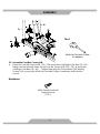
10. Assemble Handrail Arms: “R” is for right side and “L” is for left side.
A. Place the Left Handrail Arm (7L) into the U shape from Left Foot Bar (9L). Align the
hole then tighten with one Hexagon Socket Head Bolt (41), one Washer (42) and one
Nylon Locknut (44) by using the Allen Wrench and Multi Hex Tool with Phillips
Screwdriver until firm and secure.
B. Repeat the same assemble steps on the above for the Right Handrail Arm (7R).
Hardware:
19
(#41) Hexagon Socket
Head Bolt
2 PCS
(#42) Washer
2 PCS
(#44) Nylon Locknut
2 PCS
ASSEMBLY
Page is loading ...
Page is loading ...
Page is loading ...
Page is loading ...
Page is loading ...
Page is loading ...
Page is loading ...
Page is loading ...
Page is loading ...
Page is loading ...
-
 1
1
-
 2
2
-
 3
3
-
 4
4
-
 5
5
-
 6
6
-
 7
7
-
 8
8
-
 9
9
-
 10
10
-
 11
11
-
 12
12
-
 13
13
-
 14
14
-
 15
15
-
 16
16
-
 17
17
-
 18
18
-
 19
19
-
 20
20
-
 21
21
-
 22
22
-
 23
23
-
 24
24
-
 25
25
-
 26
26
-
 27
27
-
 28
28
-
 29
29
-
 30
30


Exerpeutic 1317 Owner's manual
- Type
- Owner's manual
- This manual is also suitable for
Ask a question and I''ll find the answer in the document
Finding information in a document is now easier with AI
Related papers
-
Exerpeutic 1318 Owner's manual
-
-
-
-
-
-
-
-
-
Other documents
-
 Cambridge Casual HD-870320 Installation guide
-
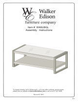 Walker Edison Furniture Company HD48UBGLAG Installation guide
-
Fitness Reality 2336 Owner's manual
-
 Cambridge Casual HD-170341T Installation guide
-
-
Home Decorators Collection KD523B Installation guide
-
 Cambridge Casual HD-225350 Installation guide
-
VEVOR LTFSYHS3BDXSFST01V0 User manual
-
Ironman Fitness 6336 Owner's manual
-
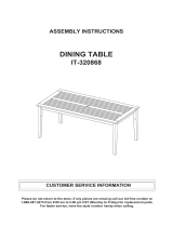 Cambridge Casual HD-320868 Installation guide


