Dell PowerVault 51F (8P Fibre Channel Switch) User guide

Category
Software manuals
Type
User guide





  
Information in this document is subject to change without notice.
© 1999–2000 Dell Computer Corporation. All rights reserved.
Reproduction in any manner whatsoever without the written permission of Dell Computer Corporation is strictly forbidden.
Trademarks used in this text: Dell, the DELL E COM logo, and PowerVault are trademarks of Dell Computer Corporation. Other
trademarks and trade names may be used in this document to refer to either the entities claiming the marks and names or their
products. Dell Computer Corporation disclaims any proprietary interest in trademarks and trade names other than its own.
Other trademarks and trade names may be used in this document to refer to either the entities claiming the marks and names or their
products. Dell Computer Corporation disclaims any proprietary interest in trademarks and trade names other than its own.
May 2000 P/N 4052U Rev. A01
v


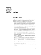
This guide is intended for system administrators, field technicians, and hardware and
software research engineers who want to use Dell PowerVault 5
x
F switches to seg-
ment their storage area network (SAN) into zones.
Chapter 1, “Introduction,” provides a definition and overview of zoning.
Chapter 2, “Zones, Components, and Configurations,” provides information
about zones themselves, the components within a zone, and how zones are
configured.
Chapter 3, “Using Zoning,” provides instruction for setting up zones, adding
members and switches, and managing zones.
Chapter 4, “Zoning Commands,” includes descriptions and examples of the
most frequently used commands for creating and managing all aspects of zones.

This guide provides information only about using PowerVault switches to create
zones. For information about setting up PowerVault switches, see the following
documents:
Dell PowerVault 56F 16-Port Fibre Channel Switch Installation and Troubleshoot-
ing Guide
Dell PowerVault 51F 8-Port Fibre Channel Switch Rack Installation Guide
Dell PowerVault 51F 8-Port Fibre Channel Switch Installation and Troubleshooting
Guide
Dell PowerVault 51F 8-Port Fibre Channel Switch User’s Guide
Dell PowerVault 50F 8-Port Fibre Channel Switch Installation and Troubleshooting
Guide
Dell PowerVault 50F 8-Port Fibre Channel Switch User's Guide
NOTE: Information updates are sometimes included with your system to describe
changes to your system or software. Always read these updates
before
consulting
any other documentation because the updates often contain the latest information.
vi
In addition to the documents mentioned above, you may receive the following types
of documentation, depending on the system and/or software you ordered from Dell.
Operating system documentation is included if you ordered your operating
system software from Dell. This documentation describes how to install (if
necessary), configure, and use your operating system software.
Documentation is included with any options you purchase separately from your
system. This documentation includes information that you need to configure and
install these options in your Dell computer.
Technical information filessometimes called readme filesmay be installed
on your hard-disk drive to provide last-minute updates about technical
changes to your system or advanced technical reference material intended for
experienced users or technicians.

The following subsections describe notational conventions used in this document.

Throughout this guide, blocks of text may be accompanied by an icon and printed in
bold type or in italic type. These blocks are notes, notices, cautions, and warnings,
and they are used as follows:
NOTE: A NOTE indicates important information that helps you make better use of your
computer system.


  !"
"#
$%&$%&!"
"#

The following list defines (where appropriate) and illustrates typographical conven-
tions used as visual cues for specific elements of text throughout this document:
Keycaps
, the labeling that appears on the keys on a keyboard, are enclosed in
angle brackets.
Example: <Enter>
Key combinations
are series of keys to be pressed simultaneously (unless other-
wise indicated) to perform a single function.
Example: <Ctrl><Alt><Enter>
vii
Commands
presented in lowercase bold are for reference purposes only and are
not intended to be typed when referenced.
Example: Use the format command to . . . .
In contrast, commands presented in the Courier New font are part of an instruc-
tion and intended to be typed.
Example: Ty p e  to format the diskette in drive A.
Filenames
and
directory names
are presented in lowercase bold.
Examples: autoexec.bat and c:\windows
Syntax lines
consist of a command and all its possible parameters. Commands
are displayed in lowercase bold; variable parameters (those for which you substi-
tute a value) are displayed in lowercase italics; constant parameters are displayed
in lowercase bold. The brackets indicate items that are optional.
Example: del [
drive
:] [
path
]
filename
[/p]
Command lines
consist of a command and may include one or more of the com-
mands possible parameters. Command lines are presented in the Courier New
font.
Example: 
Screen text
is text that appears on the screen of your monitor or display. It can be
a system message, for example, or it can be text that you are instructed to type
as part of a command (referred to as a
command line
). Screen text is presented in
the Courier New font.
Example: The following message appears on your screen:

Example: Ty p e  and press <Enter>.
Variables
are placeholders for which you substitute a value. They are presented in
italics.
Example: DIMM
x
(where
x
represents the DIMM socket designation).
viii
ix

  
Controlling SANs Through Zoning . . . . . . . . . . . . . . . . . . . . . . . . . . . . . . . . . . . . . . 1-3
    
Definition and Requirements for a Zone . . . . . . . . . . . . . . . . . . . . . . . . . . . . . . . . . 2-1
Zoning Components . . . . . . . . . . . . . . . . . . . . . . . . . . . . . . . . . . . . . . . . . . . . . . . . 2-2
Zone Members. . . . . . . . . . . . . . . . . . . . . . . . . . . . . . . . . . . . . . . . . . . . . . . . . 2-2
Physical Fabric Port Number. . . . . . . . . . . . . . . . . . . . . . . . . . . . . . . . . . . 2-2
Worldwide Name . . . . . . . . . . . . . . . . . . . . . . . . . . . . . . . . . . . . . . . . . . . 2-2
Zone Aliases . . . . . . . . . . . . . . . . . . . . . . . . . . . . . . . . . . . . . . . . . . . . . . . . . . . 2-3
Zone Configurations . . . . . . . . . . . . . . . . . . . . . . . . . . . . . . . . . . . . . . . . . . . . . 2-3
Defined Configuration . . . . . . . . . . . . . . . . . . . . . . . . . . . . . . . . . . . . . . . . 2-3
Saved Configuration . . . . . . . . . . . . . . . . . . . . . . . . . . . . . . . . . . . . . . . . . 2-3
Effective Configuration . . . . . . . . . . . . . . . . . . . . . . . . . . . . . . . . . . . . . . . 2-4
! " !
Setting Up Zoned Fabrics . . . . . . . . . . . . . . . . . . . . . . . . . . . . . . . . . . . . . . . . . . . . 3-1
Creating a Zoned Fabric . . . . . . . . . . . . . . . . . . . . . . . . . . . . . . . . . . . . . . . . . . 3-1
Adding Multiple Items . . . . . . . . . . . . . . . . . . . . . . . . . . . . . . . . . . . . . . . . . . . 3-2
Adding a New Switch. . . . . . . . . . . . . . . . . . . . . . . . . . . . . . . . . . . . . . . . . . . . 3-2
Cascading and Configuring Switches. . . . . . . . . . . . . . . . . . . . . . . . . . . . . . . . 3-3
Adding a New Fabric . . . . . . . . . . . . . . . . . . . . . . . . . . . . . . . . . . . . . . . . . . . . 3-3
Modifying a Zoned Fabric. . . . . . . . . . . . . . . . . . . . . . . . . . . . . . . . . . . . . . . . . 3-3
Adding a Device to a Configuration . . . . . . . . . . . . . . . . . . . . . . . . . . . . . . . . . 3-4
Removing a Device From a Zone Configuration. . . . . . . . . . . . . . . . . . . . . . . . 3-4
Replacing a Device in a Zone Configuration. . . . . . . . . . . . . . . . . . . . . . . . . . . 3-4
Merging Two Fabrics . . . . . . . . . . . . . . . . . . . . . . . . . . . . . . . . . . . . . . . . . . . . 3-4
Splitting a Fabric. . . . . . . . . . . . . . . . . . . . . . . . . . . . . . . . . . . . . . . . . . . . . . . . 3-4
Zone Management . . . . . . . . . . . . . . . . . . . . . . . . . . . . . . . . . . . . . . . . . . . . . . . . . 3-5
An Example of Zone Management. . . . . . . . . . . . . . . . . . . . . . . . . . . . . . . . . . 3-5
x
Zone Enforcement . . . . . . . . . . . . . . . . . . . . . . . . . . . . . . . . . . . . . . . . . . . . . . . . . 3-5
Multiswitch Fabrics. . . . . . . . . . . . . . . . . . . . . . . . . . . . . . . . . . . . . . . . . . . . . . . . . 3-6
#   #
Zone Alias Commands . . . . . . . . . . . . . . . . . . . . . . . . . . . . . . . . . . . . . . . . . . . . . . 4-1
aliCreate . . . . . . . . . . . . . . . . . . . . . . . . . . . . . . . . . . . . . . . . . . . . . . . . . . . . . . 4-1
aliDelete . . . . . . . . . . . . . . . . . . . . . . . . . . . . . . . . . . . . . . . . . . . . . . . . . . . . . . 4-2
aliAdd . . . . . . . . . . . . . . . . . . . . . . . . . . . . . . . . . . . . . . . . . . . . . . . . . . . . . . . . 4-2
aliRemove . . . . . . . . . . . . . . . . . . . . . . . . . . . . . . . . . . . . . . . . . . . . . . . . . . . . 4-2
aliShow . . . . . . . . . . . . . . . . . . . . . . . . . . . . . . . . . . . . . . . . . . . . . . . . . . . . . . 4-3
Zone Commands. . . . . . . . . . . . . . . . . . . . . . . . . . . . . . . . . . . . . . . . . . . . . . . . . . . 4-3
zoneCreate. . . . . . . . . . . . . . . . . . . . . . . . . . . . . . . . . . . . . . . . . . . . . . . . . . . . 4-3
zoneDelete. . . . . . . . . . . . . . . . . . . . . . . . . . . . . . . . . . . . . . . . . . . . . . . . . . . . 4-3
zoneAdd. . . . . . . . . . . . . . . . . . . . . . . . . . . . . . . . . . . . . . . . . . . . . . . . . . . . . . 4-4
zoneRemove . . . . . . . . . . . . . . . . . . . . . . . . . . . . . . . . . . . . . . . . . . . . . . . . . . 4-4
zoneShow . . . . . . . . . . . . . . . . . . . . . . . . . . . . . . . . . . . . . . . . . . . . . . . . . . . . 4-5
Zone Configuration Commands . . . . . . . . . . . . . . . . . . . . . . . . . . . . . . . . . . . . . . . 4-5
cfgCreate . . . . . . . . . . . . . . . . . . . . . . . . . . . . . . . . . . . . . . . . . . . . . . . . . . . . . 4-5
cfgDelete . . . . . . . . . . . . . . . . . . . . . . . . . . . . . . . . . . . . . . . . . . . . . . . . . . . . . 4-6
cfgAdd . . . . . . . . . . . . . . . . . . . . . . . . . . . . . . . . . . . . . . . . . . . . . . . . . . . . . . . 4-6
cfgRemove. . . . . . . . . . . . . . . . . . . . . . . . . . . . . . . . . . . . . . . . . . . . . . . . . . . . 4-6
cfgShow. . . . . . . . . . . . . . . . . . . . . . . . . . . . . . . . . . . . . . . . . . . . . . . . . . . . . . 4-7
Configuration Management Commands . . . . . . . . . . . . . . . . . . . . . . . . . . . . . . . . . 4-8
cfgSave . . . . . . . . . . . . . . . . . . . . . . . . . . . . . . . . . . . . . . . . . . . . . . . . . . . . . . 4-8
cfgEnable . . . . . . . . . . . . . . . . . . . . . . . . . . . . . . . . . . . . . . . . . . . . . . . . . . . . . 4-8
cfgDisable . . . . . . . . . . . . . . . . . . . . . . . . . . . . . . . . . . . . . . . . . . . . . . . . . . . . 4-8
cfgClear . . . . . . . . . . . . . . . . . . . . . . . . . . . . . . . . . . . . . . . . . . . . . . . . . . . . . . 4-9
$
%
Figure 1-1. A Fabric With Three Zones . . . . . . . . . . . . . . . . . . . . . . . . . . . . . . . . 1-2
xi
Figure 1-1. A Fabric With Three Zones . . . . . . . . . . . . . . . . . . . . . . . . . . . . . . . . 1-2
xii
support.dell.com Introduction 1-1


This guide contains information and examples of zoning for the Dell PowerVault
5xF switches, using commands run through a Telnet interface.
One or more PowerVault switches make up a Fibre Channel fabrican infrastructure
that is the backbone for deploying and managing IT resources as a network. You can
arrange devices on the same fabric into logical groups.
Zoning helps to segment storage area networks (SANs) by setting up barriers
between different operating environments and creating logical fabric subsets. With
zoning you can:
Increase environmental security where and when it is needed.
Optimize information technology (IT) resources in response to user demand and
changing user profiles.
Customize environments as needed.
Integrate support for heterogeneous environments by isolating systems that
have different operating environments or uses.
Create fabric functional areas by separating test or maintenance areas from pro-
duction areas.
Designate closed user groups by including certain zone devices for exclusive use
by zone members.
Simplify resource utilization by consolidating equipment logically for convenience.
Facilitate time-sensitive functions by creating a temporary zone used to back up a
set of devices that are members of other zones.
Secure fabric areas by providing another level of software security to control port
level access.
Zoning does not affect switch performance because it is based on the Simple Name
Server (SNS) protocol and does not impact SNS. Switch performance is hardware-
based.
Figure 1-1 shows how you can use zoning to create logical device subsets within a
SAN. This type of zoning enables resource partitioning for management and access
control.
1-2 Dell PowerVault 5xF Switches Zoning Guide

Compaq
6500
blue zone
PowerVault
651F
PowerVault
56F
loop 2
Fibre Channel fabric
green zone
red zone
PowerVault
130T DLT
PowerEdge
6350
PowerEdge
4350
PowerVault
130T DLT
PowerVault
651F
PowerVault
651F
PowerVault
651F
Interswitch
link
PowerVault
51F
PowerEdge
4350
PowerEdge
4350
PowerEdge
4350
PowerEdge
4350
PowerEdge
4350
support.dell.com Introduction 1-3

A fabric provides fast, reliable, and seamless information access within the SAN.
Within that fabric, each zone can include selected storage devices and servers. When
the zone is defined, only the devices in the defined zone can access information in
that zone.
You can configure zones dynamically, and the number of zones and zone membership
are effectively unlimited. Zones vary in size and shape, depending on the number of
fabric-connected devices and device locations. Devices may be members of more
than one zone. You can also create temporary zones, such as an enterprise backup
zone.
The following actions create and maintain zones:
Zone creation
You create and manipulate the zones, zone configurations, and
zone aliases.
Zone enforcement
The fabric automatically and transparently restricts access
to only the devices that are defined as zone members.
Zone management
You use zone commands to create, delete, and display
zones, to add or remove zone members, and to configure zone sets.
You can administer zones throughout the fabric from any switch in the fabric. A single
failure will not interrupt zoning enforcement to other SAN connections. The zoning
service automatically increases as the size of the fabric increases. You do not need to
upgrade systems when switches are added and connectivity increases.
The Fibre Channel American National Standards Institute (ANSI) standards do not
include zoning. However, zoning allows original equipment manufacturers (OEMs) and
integrators to build additional value into their offerings.
Registered state change notifications (RSCNs) and broadcast frames are restricted to
zones. RSCNs are delivered only to devices in the affected zones.
NOTE: For broadcast frames, you can use a special zone called broadcast to restrict
the delivery of broadcast frames.
1-4 Dell PowerVault 5xF Switches Zoning Guide
support.dell.com Zones, Components, and Configurations 2-1



This chapter provides information about the requirements of a zone, its components,
and zone configurations.
 !
A zone is a set of devices that access one another. Devices that are connected to a
fabric may be configured into one or more zones. Devices that are in the same zone
can see each other, while devices that are in different zones cannot.
The following are other characteristics of zones:
Every zone has a name that begins with a letter and is followed by any number of
letters, digits, and the underscore character (_).
Spaces are not allowed when naming zones.
Names are case sensitive. Therefore, Zone_1 and zone_1 are different
zones.
Every zone has a member list, consisting of one or more members. Empty zones
are not allowed. See Zone Members, found later in this chapter, for more infor-
mation on member-list specifications.
Memory usage determines the maximum number of zones and the maximum
number of members in a zone. However, because these limits are far larger than
the number of devices connected to a fabric, the number of zones and their
members are virtually unlimited.
Zone definitions are persistent. That is, the definition remains in effect across
reboots and power cycles until it is deleted or changed.
A device may be a member of multiple zones.
The remainder of this chapter discusses the components that make up a zone. For
information about creating and managing zones and configurations, refer to Chapter 3,
Using Zoning.
2-2 Dell PowerVault 5xF Switches Zoning Guide
"
In addition to the zones themselves, zoning includes several components, such as
zone members, zone aliases, and zone configurations. These components are
referred to as zone objects and are identified as follows:
Zones are specified by zone names.
Zone members are specified by physical fabric port numbers or worldwide
names. See Zone Members, found later in this chapter, for more information.
Zone aliases (symbolic names) are used to simplify zone member administration.
See Zone Aliases, found later in this chapter, for more information.
Zone configurations are sets of zones configured during zone specification. You
can select which zone configuration is in effect or disable a zone configuration at
any time.
&'
You can designate a zone member by using one of the following notations:
Physical fabric port number
Worldwide name

Use a pair of decimal numbers, separated by a comma, to specify a physical fabric
port number. For example, specifies port 6 on domain 2. The domain ID is auto-
matically assigned at the time the fabric is configured by the fabric controller.
When you specify a zone member by a physical fabric port number, all devices con-
nected to that port are in the zone. If the port is an arbitrated loop, then all loop
devices are also in the zone.

Use an eight-hex number separated by colons to specify a worldwide name, such as
.
A worldwide name provides no field information to the zone. The eight bytes are sim-
ply compared with the port names presented by a device in a login frame (FLOGI or
PLOGI). When you specify a zone member by a port name, only that single device
port is recognized by the zone.
The type of zone members used to define a zone may be mixed, like the following:
2,5; 2,7; 10:00:00:60:69:00:00:8a
support.dell.com Zones, Components, and Configurations 2-3
This zone includes any devices connected to domain 2, ports 5 and 7, and the device
with a port name of

, depending on which port it is
connected to in the fabric.
NOTE: Dell recommends zoning by worldwide name.
(
A zone alias is an alphanumeric name for one or more physical fabric port numbers or
worldwide names. These aliases simplify repetitive port number entries or worldwide
names. For example, the alias Host could be used for

.
Zone aliases have the following naming requirements:
The first character must be a capital letter.
The only valid characters are letters, numbers, underscores, and dashes.
Therefore, the alias Redzone1 is valid, whereas the alias 1Redzone is invalid.
 
A zone configuration is a set of zones. When you select a zone configuration to be in
effect, all zones that are members of that configuration are in effect. You can disable a
zone at any time, but only one zone configuration can be in effect at any given time.
The set of zone configurations defined in a fabric is a superset of the configuration
that is currently in effect. The following three subsections provide information about
the different types of zone configurations:

A defined zone configuration is a configuration that includes all changes and defini-
tions before it is saved. It is a complete set of zone objects that you have defined in
the fabric. You can define multiple zone configurations, although only one can be in
effect at a time. A configurations definition can contain inconsistencies, and zones or
aliases can be referenced even if they are not defined. A defined zone configuration
can also have duplicate members.

A saved configuration is a copy of the defined configuration saved with a given name
using the
cfgSave
command. The saved configuration and defined configuration may
differ if you have modified any zone definitions and have not saved the configuration.
A saved configuration is saved in all switches throughout the fabric and is automati-
cally reloaded by the switch on power up. If a configuration is saved again while it is in
effect, the same configuration is reinstated with an automatic
cfgEnable
command
on power up.

!"
2-4 Dell PowerVault 5xF Switches Zoning Guide
'!

"(
)
"
 
An effective configuration is a single saved zone configuration that is currently
enabled on the fabric.
An effective configuration is compiled by checking for undefined zone names, zone
aliases, or other inconsistencies, expanding zone aliases, removing duplicate entries,
and then enabling the configuration.
If the compilation fails, the previous configuration remains in effect. If the compilation
succeeds, the previous configuration is disabled.

!"
'!

support.dell.com Using Zoning 3-1


This chapter contains information and examples for monitoring PowerVault 5xF
switches by using zoning. The following topics are discussed in this chapter:
Setting up zoned fabrics
Zone management
Zone enforcement
Multiswitch fabrics
#"$
There are three zone object types for which you use Telnet commandsalias, zone,
and configuration. For these three object types, you can issue the following five
commands:
Create
Delete
Add
Remove
Show
The following subsections provide information about the steps to perform when exe-
cuting these commands. For more information and examples of the commands
themselves, see Chapter 4, Zoning Commands.
%'
To create a zoned fabric, perform the following steps:
1. Map out the desired fabric configuration.
2. Define the core aliases.
3. Define the zones.
4. Define the zone configuration and save it.
3-2 Dell PowerVault 5xF Switches Zoning Guide
5. Enable the configuration.
6. Test the configuration.
7. Save the configuration again.
NOTE: Before issuing any zoning commands, use the
switchShow
command on
each switch in the zoned fabric to verify that all switches in the fabric are connected.
All ports used for interswitch links (ISL) display the neighboring switches worldwide
name (WWN) and switch name.
(&
Use the following syntax to add multiple items to a zone:
zoneAdd "
name_of_zone
", "
member; member; member
"
For example, zoneAdd " !", "1,10;1,12" adds domain 1, port 10 and
domain 1, port 12 to zone "Red_zone".
Apply the same syntax when adding aliases (aliAdd) or configurations (cfgAdd).
Members are separated by semicolons but within a single pair of quotes.
The following commands can take multiple-item parameter lists:
Configuration commands, such as cfgCreate, cfgAdd, and cfgRemove
Zone commands, such as zoneCreate, zoneAdd, and zoneRemove
Alias commands, such as aliCreate, aliAdd, and aliRemove
()*)
A new switch is a switch that has not previously been connected to a fabric with zon-
ing configured and that has had no zone configuration data entered into it. You can
return a switch to the new state by using the cfgClear command before connecting
it to the fabric. For zoning purposes, other parameters, such as IP addresses, remain
unchanged.
(!
!
When you connect a new switch to a fabric, all zone configuration data is immediately
copied from the fabric into the new switch. If a zone configuration is enabled in the
fabric, then the same configuration becomes enabled in the new switch. After this
operation, the cfgShow
command displays the same output on all switches in the
fabric, including the new switch.
NOTE: When connecting two switches using ISLs to form a fabric, if there is a differ-
ence in the configuration information relating to any zone objects (aliases, zones, or
configurations) with the same name, the switches cannot connecteven if none of
the defined configurations are enabled.
  • Page 1 1
  • Page 2 2
  • Page 3 3
  • Page 4 4
  • Page 5 5
  • Page 6 6
  • Page 7 7
  • Page 8 8
  • Page 9 9
  • Page 10 10
  • Page 11 11
  • Page 12 12
  • Page 13 13
  • Page 14 14
  • Page 15 15
  • Page 16 16
  • Page 17 17
  • Page 18 18
  • Page 19 19
  • Page 20 20
  • Page 21 21
  • Page 22 22
  • Page 23 23
  • Page 24 24
  • Page 25 25
  • Page 26 26
  • Page 27 27
  • Page 28 28
  • Page 29 29
  • Page 30 30
  • Page 31 31
  • Page 32 32
  • Page 33 33
  • Page 34 34
  • Page 35 35
  • Page 36 36
  • Page 37 37
  • Page 38 38

Dell PowerVault 51F (8P Fibre Channel Switch) User guide

Category
Software manuals
Type
User guide

Ask a question and I''ll find the answer in the document

Finding information in a document is now easier with AI