Page is loading ...

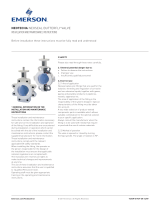
KEYSTONE GULF VALVES CHECK VALVES MODEL MB
INSTALLATION, OPERATION AND MAINTENANCE INSTRUCTIONS
© 2017 Emerson. All rights reserved.
SPARE PARTS
WARNING
Do not attempt to work on any valve under
pressure, and depending on the service, valve
surface temperature may be hot. Use proper
protective equipment to protect against burns.
Also, provide safe means in case of uncontrolled
release of fluids.
Any misuse, unauthorized modification,
refurbishment by unqualified staff or use of
non-Emerson parts invalidates the Warranty
provided in the Terms and Conditions of Sale
and invalidate the CE Mark if applicable..
INTRODUCTION
The instructions included within this installation
and operations manual are intended as a
guideline only. As they do not cover every
situation, this manual does not replace
common sense and expertise of the person
installing the valve and pipeline engineer(s).
Proper valve selection is the foundation for
successful installation and the End User is
responsible for ordering the correct valves.
Should you require assistance, please contact
Emerson.
While every effort has been made to ensure the
accuracy of the contents of this IOM, it is not
to be interpreted as warranties or guarantees,
expressed or implied, regarding the products
and services described herein or their use or
applicability. Emerson reserves the right to
modify or improve the designs or specifications
of such products at any time.
Emerson.com/FinalControl
Before installation these instructions must be read fully and understood
VCIOM-04509-EN 17/10
The use of the term “PED” throughout this
manual refer to the European Pressure
Equipment Directive 97/23/EC. Please note that
not all Emerson valve configurations comply
with CE/PED/ASME standards.
The Keystone Model MB wafer check valve
is a self-operating check valve designed to
prevent the backflow of gas or liquid media.
Initial opening of the discs begins when the
upstream pressure exceeds the downstream
pressure and the effective torque of the spring.
This pressure is called the “cracking” pressure.
Once the discs open, flow velocity determines
the position and stability of the discs. If the flow
velocity upstream of the check valve decreases
and/or stops, the springs force the discs to a
closed position.
If valve is resold or transferred, it is your
responsibility to forward this instruction
manual along with the product to the new
owner or transferee.

2
KEYSTONE GULF VALVES CHECK VALVES MODEL MB
INSTALLATION, OPERATION AND MAINTENANCE INSTRUCTIONS
INSTALLATION
1. Remove the valve from carton or packing
skid. Prior to installation, inspect valve(s)
for any damage and check valve(s) and
nameplate(s) for proper identification and
to be sure the valve is suitable for use in the
application.
2. The protective rust proof coating on the
internal parts of steel or cast iron valves
should be removed by brushing out with any
standard petroleum solvent (e.g. Varsol™,
Kerosene), and air dry. Ensure internal parts
operate freely.
3. Stainless Steel or Bronze valves need only
to be wiped clean and installed.
4. In horizontal flow installation, the hinge pin
must be vertical.
5. Ensure the sealing surfaces are free of dirt
and insert the valve between two companion
flanges of the same series as the valve and
place gaskets on flange faces. The arrow on
the valve or nameplate indicating direction
of flow should coincide with line flow. Install
studs through companion flanges and
tighten, using standard industry practice.
6. In liquid service we recommend valve be
installed at least five (5) pipe diameters
downstream from a pump discharge and/or
other pipefittings for maximum service life.
LIMITATIONS AND PRECAUTIONS
WARNING
Any misuse, unauthorized modification,
refurbishment by unqualified staff or use of non-
Emerson parts invalidates the Warranty provided
in the Terms and Conditions of Sale and invalidate
the CE Mark if applicable.
Model MB dual disc wafer check valves are
not recommended for the following service
conditions:
• Pulsating flows.
•
Service condition requiring a “Full Port” opening.
• Installation directly to a butterfly valve or other
piping accessory that may interfere with the
opening or closing of valve discs.
• Vertical flow DOWN without prior factory
approval.
•
The design of the Model MB dual disc wafer check
valves has taken into account loadings appropriate
to its intended use and other reasonably
foreseeable operating conditions. Loadings
caused by traffic, wind and earthquake have not
been taken into account.
• Model MB dual disc wafer check valves are not
to be installed in service conditions greater
than Category III (Reference the PED).
• A minimum of 5 (five) pipe diameters should
be maintained between the wafer check and
likely causes of turbulence (i.e. pump discharge,
reducers, elbows, and tees, etc.).
• Maximum operating pressure reduces as
service temperature increases.
• It is the responsibility of the customer to ensure
valve is suitable for all service conditions of
the line, including but not limited to pressure,
temperature, and media. The application is
not to allow corrosion greater than 0.05 mm
/ year (0.002” / year). DO NOT use any valve
in applications where either the pressure
or temperature is higher than the allowable
working values or service media is incompatible
with materials of construction, which may cause
chemical attacks.
Media
Flow rate
Feet per second (ft/s) Meters per second (m/s)
Liquid 3 to 11 0.91 to 3.35
Gas 20 to 250 6.1 to 76.2
The following precautions should be taken to
insure long service life of wafer check valves:
• Accurate sizing of wafer checks is crucial to
ensure an acceptable pressure drop and a long
service life.
• Flow velocities should be in the following
ranges:

3
DISASSEMBLY
Disassembly of the wafer check valve is
moderately simple using a hammer, allen-
wrench, bronze round nose punch and Locktite
thread sealant and the following instructions.
Please use caution when removing the stop or
hinge shaft. Preset spring(s) may cause serious
injury when tension is released.
1. Lay the body down with downstream side
facing upward.
2. Remove retainer insert set screws with
allen-head wrench.
3. Place two 100 mm x 100 mm (4” x 4”) boards
on the flanges directly opposite of each other.
4. Carefully, without changing the distance
between the two boards, set them on a hard
surface.
5. Turn valve body and set the valve body on
the two boards so that the upstream side
is facing upward. Make sure that the discs
hang down without any interference with the
boards.
6. Remove the discs from the valve by placing
a brass round nose punch on the left disc’s
hinge and gently tap on the punch with a
hammer. Alternate this process between
the left and right discs’ hinge until the disc
fall free from the valve body.
7. Mark the retainer insert and valve body to
insure the inserts are replaced in the same
area of the valve body.
8. Remove the retainer inserts from the hinge
and stop pins.
9. While maintaining pressure on spring with
hand, remove the hinge pin from the discs’
hinge lugs, and spring. Release spring.
ASSEMBLY
1. Lay the body down with downstream side
facing upward.
2. Lay the discs on a hard surface with disc
seating surface facing downward and the
disc hinge lugs together.
3.
Slide hinge pin through the disc’s hinge lugs.
4. Rotate the forward spring leg clockwise,
with spring legs pointing downward. Larger
valves have two springs.
5. Place wound spring(s) between the discs on
the center post.
6. While maintaining pressure on spring(s)
with hand, insert hinge pin through the
remaining spring(s), discs’ hinge lugs, and
thrust bushing. Release spring.
7. Attach the retainer inserts to the hinge and
stop pin.
8. Insert discs assembly into valve body and
alternately, tap the retainer inserts into the
valve body.
9. Move the valve to a position so that the
hinge pin is vertical.
10. Open and close the discs to make sure there
is no interference between the valve seat
and discs’ movement.
11. Insert retainer insert into valve body slot -
making sure that the retainer is inserted
into the slot that it was removed from.
12. Screw retainer insert set screws into the
valve body/retainer insert with allen head
wrench.
KEYSTONE GULF VALVES CHECK VALVES MODEL MB
INSTALLATION, OPERATION AND MAINTENANCE INSTRUCTIONS
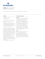
PARTS LIST
Item Description
1 Body
2 Disc
3 Seat
4 Spring
5 Hinge pin
6 Stop pin
7 Retainer insert
8 Bearing
9 Set screw
ASSEMBLY AND DISASSEMBLY
NOTE
For check valves with elastomer seats - the original
elastomer seat is bonded and vulcanized to the
valve body. Emerson does not recommend that the
elastomer seat be replaced, except by Emerson.
Emerson does not warrant nor shall Emerson be
liable for special, indirect, incidental or consequential
damages.
Eye protection is recommended when disassembling
and assembling wafer check valves.

4
Neither Emerson, Emerson Automation Solutions, nor any of their affiliated entities assumes responsibility for the selection, use or maintenance of any product.
Responsibility for proper selection, use, and maintenance of any product remains solely with the purchaser and end user.
Keystone is a mark owned by one of the companies in the Emerson Automation Solutions business unit of Emerson Electric Co. Emerson Automation Solutions, Emerson
and the Emerson logo are trademarks and service marks of Emerson Electric Co. All other marks are the property of their respective owners.
The contents of this publication are presented for informational purposes only, and while every effort has been made to ensure their accuracy, they are not to be
construed as warranties or guarantees, express or implied, regarding the products or services described herein or their use or applicability. All sales are governed by
our terms and conditions, which are available upon request. We reserve the right to modify or improve the designs or specifications of such products at any time without
notice.
Emerson.com/FinalControl
/