Dell Storage NX3330 Owner's manual
- Category
- Servers
- Type
- Owner's manual

Dell Storage NX3330 Owner's Manual
Regulatory Model: E26S Series
Regulatory Type: E26S001
August 2020
Rev. A02

Notes, cautions, and warnings
NOTE: A NOTE indicates important information that helps you make better use of your product.
CAUTION: A CAUTION indicates either potential damage to hardware or loss of data and tells you how to avoid the
problem.
WARNING: A WARNING indicates a potential for property damage, personal injury, or death.
© 2017 - 2020 Dell Inc. or its subsidiaries. All rights reserved. Dell, EMC, and other trademarks are trademarks of Dell Inc. or its subsidiaries. Other
trademarks may be trademarks of their respective owners.

Chapter 1: About your system.......................................................................................................... 7
Front-panel features and indicators.................................................................................................................................... 7
LCD panel..........................................................................................................................................................................8
Back panel features and indicators....................................................................................................................................10
Diagnostic indicators.............................................................................................................................................................11
Hard drive indicator codes.................................................................................................................................................. 12
iDRAC Direct LED indicator codes.....................................................................................................................................13
NIC indicator codes..............................................................................................................................................................14
Power supply unit indicator codes..................................................................................................................................... 14
Locating your system Service Tag.....................................................................................................................................16
Chapter 2: Documentation resources...............................................................................................17
Chapter 3: Technical specifications.................................................................................................19
Chapter 4: Initial system setup and configuration............................................................................ 23
Setting up your system.......................................................................................................................................................23
iDRAC configuration............................................................................................................................................................23
Options to set up iDRAC IP address........................................................................................................................... 23
Log in to iDRAC..............................................................................................................................................................24
Options to install the operating system............................................................................................................................24
Methods to download firmware and drivers.............................................................................................................. 24
Manage your system...........................................................................................................................................................24
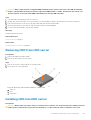
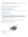
Chapter 5: Pre-operating system management applications............................................................. 26
Options to manage the pre-operating system applications...........................................................................................26
System Setup.......................................................................................................................................................................26
Viewing System Setup..................................................................................................................................................26
System Setup details.....................................................................................................................................................27
System BIOS.................................................................................................................................................................. 27
iDRAC Settings utility....................................................................................................................................................44
Device Settings..............................................................................................................................................................45
Dell Lifecycle Controller......................................................................................................................................................45
Embedded systems management............................................................................................................................... 45
Boot Manager...................................................................................................................................................................... 45
Viewing Boot Manager................................................................................................................................................. 45
Boot Manager main menu............................................................................................................................................ 45
PXE boot.............................................................................................................................................................................. 46
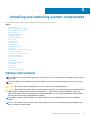
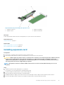
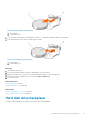
Chapter 6: Installing and removing system components................................................................... 47
Safety instructions...............................................................................................................................................................47
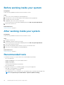
Before working inside your system................................................................................................................................... 48
After working inside your system...................................................................................................................................... 48
Recommended tools........................................................................................................................................................... 48
Contents
Contents 3

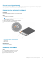
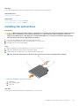
Front bezel (optional)......................................................................................................................................................... 49
Removing the optional front bezel.............................................................................................................................. 49
Installing front bezel...................................................................................................................................................... 49
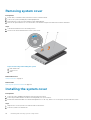
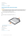
Removing system cover.....................................................................................................................................................50
Installing the system cover.................................................................................................................................................50
Inside system........................................................................................................................................................................ 51
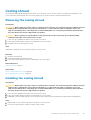
Cooling shroud.....................................................................................................................................................................53
Removing the cooling shroud.......................................................................................................................................53
Installing the cooling shroud.........................................................................................................................................53
System memory...................................................................................................................................................................54
General memory module installation guidelines......................................................................................................... 56
Mode-specific guidelines.............................................................................................................................................. 56
Sample memory configurations................................................................................................................................... 57
Removing memory modules.........................................................................................................................................59
Installing memory modules........................................................................................................................................... 60
Hard disk drives................................................................................................................................................................... 62
Removing 2.5 inch HDD blank..................................................................................................................................... 62
Installing 2.5 inch HDD blank........................................................................................................................................63
Removing hot-swappable HDD................................................................................................................................... 63
Installing hot-swappable HDD......................................................................................................................................64
Removing HDD from HDD carrier............................................................................................................................... 65
Installing HDD into HDD carrier................................................................................................................................... 65
Optical drive (optional).......................................................................................................................................................66
Removing optical drive..................................................................................................................................................66
Installing the optical drive............................................................................................................................................. 67
Removing the slim optical drive blank.........................................................................................................................68
Installing the slim optical drive blank........................................................................................................................... 69
Cooling fans..........................................................................................................................................................................69
Removing cooling fan....................................................................................................................................................70
Installing cooling fan...................................................................................................................................................... 70
Expansion cards and expansion card riser.........................................................................................................................71
Expansion card installation guidelines.......................................................................................................................... 71
Removing expansion card.............................................................................................................................................72
Installing expansion card............................................................................................................................................... 73
Removing expansion-card risers..................................................................................................................................74
Installing expansion card risers.....................................................................................................................................75
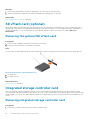
SD vFlash card (optional)...................................................................................................................................................76
Removing the optional SD vFlash card.......................................................................................................................76
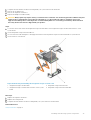
Integrated storage controller card.....................................................................................................................................76
Removing integrated storage controller card............................................................................................................ 76
Installing integrated storage controller card...............................................................................................................78
Network daughter card.......................................................................................................................................................78
Removing NDC...............................................................................................................................................................78
Installing the network daughter card.......................................................................................................................... 80
Processors and heat sinks...................................................................................................................................................81
Removing a processor................................................................................................................................................... 81
Installing a processor.....................................................................................................................................................83
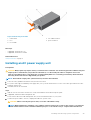
PSUs..................................................................................................................................................................................... 85
Hot spare feature.......................................................................................................................................................... 86
Removing the power supply unit blank.......................................................................................................................86
4
Contents

Installing the power supply unit blank..........................................................................................................................87
Removing an AC power supply unit............................................................................................................................ 88
Installing an AC power supply unit...............................................................................................................................89
System battery.................................................................................................................................................................... 90
Replacing the system battery......................................................................................................................................90
Hard disk drive backplane................................................................................................................................................... 91
Removing HDD backplane............................................................................................................................................92
Installing HDD backplane.............................................................................................................................................. 93
Control panel........................................................................................................................................................................94
Removing control panel board–8 HDD system......................................................................................................... 94
Installing the control panel board–eight hard drive system.....................................................................................95
Removing control panel–8 HDD system.................................................................................................................... 96
Installing control panel–8 HDD system.......................................................................................................................97
VGA module......................................................................................................................................................................... 98
Removing the VGA module..........................................................................................................................................98
Installing the VGA module............................................................................................................................................ 99
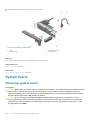
System board..................................................................................................................................................................... 100
Removing system board..............................................................................................................................................100
Installing system board................................................................................................................................................ 102
Restoring the Service Tag by using the Easy Restore feature.............................................................................. 104
Trusted Platform Module..................................................................................................................................................104
Installing the Trusted Platform Module.....................................................................................................................104
Initializing the TPM for BitLocker users....................................................................................................................105
Initializing the TPM for TXT users............................................................................................................................. 105
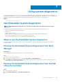
Chapter 7: Using system diagnostics............................................................................................. 107
Dell Embedded System Diagnostics................................................................................................................................ 107
When to use the Embedded System Diagnostics....................................................................................................107
Running the Embedded System Diagnostics from Boot Manager........................................................................ 107
Running the Embedded System Diagnostics from the Dell Lifecycle Controller................................................. 107
System diagnostic controls.........................................................................................................................................108
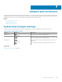
Chapter 8: Jumpers and connectors ............................................................................................. 109
System board jumper settings......................................................................................................................................... 109
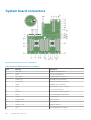
System board connectors................................................................................................................................................. 110
Disabling forgotten password............................................................................................................................................112
Chapter 9: Troubleshooting your system........................................................................................ 113
Troubleshooting system startup failure........................................................................................................................... 113
Troubleshooting external connections.............................................................................................................................113
Troubleshooting the video subsystem............................................................................................................................. 114
Troubleshooting a USB device..........................................................................................................................................114
Troubleshooting iDRAC Direct (USB XML configuration)............................................................................................ 115
Troubleshooting iDRAC Direct (Laptop connection).....................................................................................................115
Troubleshooting a serial I/O device..................................................................................................................................116
Troubleshooting a NIC....................................................................................................................................................... 116
Troubleshooting a wet system..........................................................................................................................................117
Troubleshooting a damaged system.................................................................................................................................117
Troubleshooting the system battery................................................................................................................................ 118
Contents
5

Troubleshooting power supply units.................................................................................................................................119
Troubleshooting power source problems...................................................................................................................119
Power supply unit problems........................................................................................................................................ 119
Troubleshooting cooling problems....................................................................................................................................119
Troubleshooting cooling fans............................................................................................................................................120
Troubleshooting system memory.....................................................................................................................................120
Troubleshooting an internal USB key............................................................................................................................... 121
Troubleshooting an optical drive...................................................................................................................................... 122
Troubleshooting a tape backup unit................................................................................................................................ 122
Troubleshooting a hard drive or SSD...............................................................................................................................123
Troubleshooting a storage controller...............................................................................................................................124
Troubleshooting expansion cards.....................................................................................................................................124
Troubleshooting processors............................................................................................................................................. 125
System messages.............................................................................................................................................................. 126
Warning messages....................................................................................................................................................... 126
Diagnostic messages................................................................................................................................................... 126
Alert messages............................................................................................................................................................. 126
Chapter 10: Getting help...............................................................................................................127
Contacting Dell................................................................................................................................................................... 127
Documentation feedback..................................................................................................................................................127
Quick Resource Locator ...................................................................................................................................................127
6
Contents

About your system
The Dell Storage NX3330 is a rack system that supports up to two processors based on the Intel Haswell E5-2600 v3 processor family, up
to 24 DIMMs, and storage capacity up to eight internal, hot-swappable 2.5-inch hard disk drives (HDDs).
Topics:
• Front-panel features and indicators
• Back panel features and indicators
• Diagnostic indicators
• Hard drive indicator codes
• iDRAC Direct LED indicator codes
• NIC indicator codes
• Power supply unit indicator codes
• Locating your system Service Tag
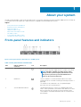
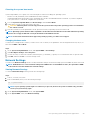
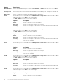
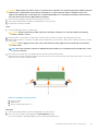
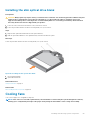
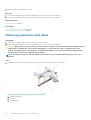
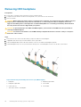
Front-panel features and indicators
Figure 1. Front-panel features and indicators—8 HDD system
Table 1. Front-panel features and indicators
Item Indicator, Button, or
Connector
Icon Description
1 Turn on indicator, power button The turn on indicator glows when the system is turn on. The power
button controls the power supply unit (PSU) output to the system.
NOTE: On ACPI-compliant operating systems (OSs),
turning off the system using the power button causes
the system to perform a graceful shutdown before
power to the system is turned off.
2 NMI button
Used to troubleshoot software and device driver errors when
running certain OSs. This button can be pressed using the end of a
paper clip.
Use this button only if directed to do so by qualified support
personnel or by the OS documentation.
3 System identification button The identification buttons on the front- and back panels can be
used to locate a particular system within a rack. When one of these
buttons is pressed, the LCD panel on the front and the system
status indicator on the back flashes blue until one of the buttons is
pressed again.
1
About your system 7

Table 1. Front-panel features and indicators (continued)
Item Indicator, Button, or
Connector
Icon Description
Press to toggle the system ID to ON or OFF. If the system stops
responding during POST, press and hold the system ID button for
more than five seconds to enter BIOS progress mode.
To reset the iDRAC (if not disabled on the iDRAC Setup page by
pressing F2) press and hold the button for more than 15 seconds.
4 USB management port/iDRAC
Direct (2)
Allows you to connect USB drives to the system or provides access
to the iDRAC Direct features. For more information, see the
Integrated Dell Remote Access Controller User's Guide at
dell.com/esmmanuals. The ports are USB 2.0-compliant.
5 Optical drive One optional SATA DVD-ROM drive or DVD+/-RW drive.
NOTE: DVD devices are data only.
6 SD vFlash media card slot Allows you to insert a vFlash media card.
7 LCD menu buttons Allows you to navigate the control panel LCD menu.
8 Information tag A slide-out label panel which that allows you to record system
information, such as Service Tag, NIC, and MAC address.
9 LCD panel Displays system ID, status information, and system error messages.
The LCD lights blue during normal system operation. When the
system needs attention, the LCD lights amber and the LCD panel
displays an error code followed by descriptive text.
NOTE: If the system is connected to AC power and an
error is detected, the LCD lights amber regardless of
whether the system is turned on or turned off.
10 Quick Sync (optional)
NOTE: By default, Quick Sync option is not available for
Dell Storage NX3330 system.
Indicates a Quick Sync-enabled system. The Quick Sync feature is
optional and requires a Quick Sync bezel. This feature allows
management of the system by using mobile devices. This feature
aggregates hardware or firmware inventory and various system
level diagnostic or error information that can be used in
troubleshooting the system. For more information, see the
Integrated Dell Remote Access Controller User’s Guide at
dell.com/esmmanuals.
11 Video connector Allows you to connect a VGA display to the system.
12 HDDs (8) Up to eight 2.5 inch hot-swappable HDDs.
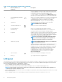
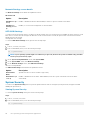
LCD panel
The LCD panel of your system provides system information, status, and error messages to indicate if the system is functioning correctly or
if the system needs attention. For more information about error messages, see the Dell Event and Error Messages Reference Guide at
Dell.com/openmanagemanuals >OpenManage software.
• The LCD backlight turns blue during normal operating conditions.
• When the system needs attention, the LCD turns amber, and displays an error code followed by descriptive text.
NOTE:
If the system is connected to a power source and an error is detected, the LCD turns amber regardless of
whether the system is turned on or off.
• The LCD backlight is turned off when the system is in standby mode and can be turned on by pressing either the Select, Left, or Right
button on the LCD panel.
• The LCD backlight remains off if LCD messaging is turned off using the iDRAC utility, the LCD panel, or other tools.
8
About your system

Figure 2. LCD panel features
Table 2. LCD panel features
Item Button Description
1 Left Moves the cursor back in one-step increments.
2 Select Selects the menu item highlighted by the cursor.
3 Right Moves the cursor forward in one-step increments.
During message scrolling:
• Press and hold the button to increase scrolling speed.
• Release the button to stop.
NOTE: The display stops scrolling when the button is released. After 45
seconds of inactivity, the display starts scrolling.
Viewing Home screen
The Home screen displays user-configurable information about the system. This screen is displayed during normal system operation when
there are no status messages or errors. When the system is in standby mode, the LCD backlight turns off after a few minutes of inactivity,
if there are no error messages.
Steps
1. To view the Home screen, press one of the three navigation buttons (Select, Left, or Right).
2. To navigate to the Home screen from another menu, complete the following steps:
a. Press and hold the navigation button till the up arrow
is displayed.
b. Navigate to the
using the up arrow
c. Select the Home icon.
d. On the Home screen, press the Select button to enter the main menu.
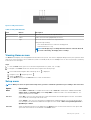
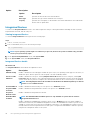
Setup menu
NOTE: When you select an option in the Setup menu, you must confirm the option before proceeding to the next action.
Option Description
iDRAC Select DHCP or Static IP to configure the network mode. If Static IP is selected, the available fields are IP,
Subnet (Sub), and Gateway (Gtw). Select Setup DNS to enable DNS and to view domain addresses. Two
separate DNS entries are available.
Set error Select SEL to view LCD error messages in a format that matches the IPMI description in the SEL. This enables
you to match an LCD message with an SEL entry.
Select Simple to view LCD error messages in a simplified user-friendly description. For more information about
error messages, see the Dell Event and Error Messages Reference Guide at Dell.com/openmanagemanuals >
OpenManage software.
Set home Select the default information to be displayed on the Home screen. See View menu section for the options and
option items that can be set as the default on the Home screen.
About your system 9

Related References
View menu on page 10
View menu
NOTE: When you select an option in the View menu, you must confirm the option before proceeding to the next action.
Option Description
iDRAC IP Displays the IPv4 or IPv6 addresses for iDRAC8. Addresses include DNS (Primary and Secondary), Gateway,
IP, and Subnet (IPv6 does not have Subnet).
MAC Displays the MAC addresses for iDRAC, iSCSI, or Network devices.
Name Displays the name of the Host, Model, or User String for the system.
Number Displays the Asset tag or the Service tag for the system.
Power Displays the power output of the system in BTU/hr or Watts. The display format can be configured in the Set
home submenu of the Setup menu.
Temperature Displays the temperature of the system in Celsius or Fahrenheit. The display format can be configured in the Set
home submenu of the Setup menu.
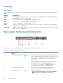
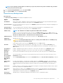
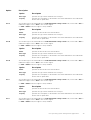
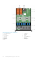
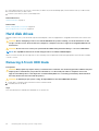
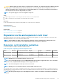
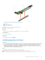
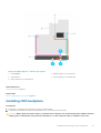
Back panel features and indicators
Figure 3. Back panel features and indicators—8 HDD system—3 PCIe expansion cards
Table 3. Back panel features and indicators
Item Indicator, Button, or
Connector
Icon Description
1 System identification button The identification buttons on the front-and back panels can be
used to locate a particular system within a rack. When one of these
buttons is pressed, the LCD panel on the front and the system
status indicator on the back blinks until one of the buttons is
pressed again.
Press to toggle the system ID on and off. If the system stops
responding during POST, press and hold the system ID button for
more than five seconds to enter BIOS progress mode.
To reset iDRAC (if not disabled on the iDRAC Setup page by
pressing F2), press and hold for more than 15 seconds.
2 System identification connector Allows you to connect the optional system status indicator
assembly through the optional cable management arm.
3 iDRAC8 Enterprise port Dedicated management port.
NOTE: The port is available for use only if the iDRAC8
Enterprise license is installed on your system.
10 About your system

Table 3. Back panel features and indicators (continued)
Item Indicator, Button, or
Connector
Icon Description
4 LP PCIe expansion card slot
(riser 1)
Allows you to connect a low profile PCIe expansion card.
5 Serial connector Allows you to connect a serial device to the system.
6 LP PCIe expansion card slot
(riser 2)
Allows you to connect a low profile PCIe expansion card.
7 Video connector Allows you to connect a VGA display to the system.
8 USB connectors (2) Allows you to connect USB drives to the system. The ports are
USB 3.0-compliant.
9 LP PCIe expansion card slot
(riser 3)
Allows you to connect a low profile PCIe expansion card.
10 Ethernet connectors (4) Four integrated 10/100/1000 Mbps NIC connectors
Or
Four integrated connectors:
• Two integrated 10/100/1000 Mbps NIC connectors
• Two integrated 100 Mbps/1 Gbps/10 Gbps SFP+ connectors
11 PSU 1 750 W AC PSUs
12 PSU 2 750 W AC PSUs
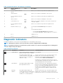
Diagnostic indicators
The diagnostic indicators on the system front panel display error status during system startup.
NOTE: The diagnostic indicators are not present if the system is equipped with an LCD display.
NOTE: No diagnostic indicators are lit when the system is turned off. To start the system, plug it into a working power
source and press the power button.
Table 4. Diagnostic indicators
Icon Description Condition Corrective action
Health indicator If the system is turned on, and in good
health, the indicator glows solid blue.
None required.
The indicator blinks amber if the
system is turned on or in standby, and
if any error exists (for example, a
failed fan or HDD).
See the System Event Log or system messages for the
specific issue. For more information about error
messages, see the Dell Event and Error Messages
Reference Guide at Dell.com/esmmanuals.
Invalid memory configurations can cause the system to
stop responding at startup without any video output. See
the Getting help section in this document.
HDD indicator The indicator blinks amber if a hard
drive experiences an error.
See the System Event Log to determine the HDD that
has an error. Run the appropriate Online Diagnostics test.
Restart system and run embedded diagnostics (ePSA). If
the HDDs are configured in a RAID array, restart the
system and start the host adapter configuration utility
program.
Electrical
indicator
The indicator blinks amber if the
system experiences an electrical error
(for example, voltage out of range, or
a failed PSU or voltage regulator).
See the System Event Log or system messages for the
specific issue. If it is because of an issue with the PSU,
check the LED on the PSU. Reseat the PSU by removing
About your system 11

Table 4. Diagnostic indicators (continued)
Icon Description Condition Corrective action
and reinstalling it. If the issue persists, see the Getting
help section in this document.
Temperature
indicator
The indicator blinks amber if the
system experiences a thermal error
(for example, a temperature out of
range or fan failure).
Ensure that none of the following conditions exist:
• A cooling fan is removed or has failed.
• System cover, cooling shroud, EMI filler panel,
memory-module blank, or back-filler bracket is
removed.
• Ambient temperature is too high.
• External airflow is obstructed.
See the Getting help section in this document.
Memory indicator The indicator blinks amber if a
memory error occurs.
See the system event log or system messages for the
location of the failed memory. Reinstall the memory
device. If the issue persists, see the Getting help section
in this document.
PCIe indicator The indicator blinks amber if a PCIe
card experiences an error.
Restart the system. Update any required drivers for the
PCIe card. Reinstall the card. If the issue persists, see the
Getting help section in this document.
NOTE: For more information on supported PCIe
cards, see the Expansion Card Installation
Guidelines section in this document.
Related References
Getting help on page 127
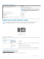
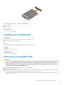
Hard drive indicator codes
Figure 4. Hard drive indicators
1. Hard drive activity indicator
2. Hard drive status indicator
3. Hard drive
NOTE:
If the hard drive is in Advanced Host Controller Interface (AHCI) mode, the status indicator (on the right side)
does not function and remains turned off.
12 About your system

Table 5. Hard drive indicator codes
Drive-status indicator pattern (RAID only) Condition
Blinks green two times per second Identifying drive or preparing for removal.
Off Drive ready for insertion or removal.
NOTE: The drive status indicator remains off until all hard
drives are initialized after the system is turned on. Drives are
not ready for insertion or removal during this time.
Blinks green, amber, and turns off Predicted drive failure
Blinks amber four times per second Drive failed
Blinks green slowly Drive rebuilding
Steady green Drive online
Blinks green three seconds, amber three seconds, and turns
off six seconds
Rebuild aborted
iDRAC Direct LED indicator codes
The iDRAC Direct LED indicator lights up to indicate that the port is connected and is being used as a part of the iDRAC subsystem.
NOTE: The iDRAC Direct LED indicator does not turn on when the USB port is used in the USB mode.
1. iDRAC Direct status indicator
The iDRAC Direct LED indicator table describes iDRAC Direct activity when configuring iDRAC Direct by using the management port (USB
XML Import).
Table 6. iDRAC Direct LED indicators
Convention iDRAC Direct LED
indicator pattern
Condition
A Green
Turns green for a minimum of two seconds to indicate the start and end of a
file transfer.
B Flashing green Indicates file transfer or any operation tasks.
C Green and turns off Indicates that the file transfer is complete.
D Not lit Indicates that the USB is ready to be removed or that a task is complete.
The following table describes iDRAC Direct activity when configuring iDRAC Direct by using your laptop and cable (Laptop Connect):
Table 7. iDRAC Direct LED indicator patterns
iDRAC Direct LED indicator pattern Condition
Solid green for two seconds
Indicates that the laptop is connected.
About your system 13

Table 7. iDRAC Direct LED indicator patterns (continued)
iDRAC Direct LED indicator pattern Condition
Flashing green (on for two seconds and
off for two seconds)
Indicates that the laptop connected is recognized.
Turns off Indicates that the laptop is unplugged.
NIC indicator codes
EachThe NIC on the back panel has an indicator that provides information about the network activity and link status. The activity LED
indicates whether the NIC is currently connected or not. The link LED indicates the speed of the connected network.
Figure 5. NIC indicators
1. link indicator
2. activity indicator
Table 8. NIC indicators
Convention Status Condition
A Link and activity indicators are off The NIC is not connected to the network.
B Link indicator is green The NIC is connected to a valid network at its
maximum port speed (1 Gbps or 10 Gbps).
C Link indicator is amber The NIC is connected to a valid network at less than
its maximum port speed.
D Activity indicator is flashing green Network data is being sent or received.
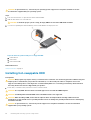
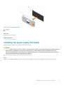
Power supply unit indicator codes
AC power supply units (PSUs) have an illuminated translucent handle that serves as an indicator and DC PSUs have an LED that serves as
an indicator. The indicator shows whether power is present or a power fault has occurred.
14
About your system

Figure 6. AC PSU status indicator
1. AC PSU status indicator/handle
Table 9. AC PSU status indicators
Convention Power indicator
pattern
Condition
A Green A valid power source is connected to the PSU and the PSU is operational.
B Flashing green When the firmware of the PSU is being updated, the PSU handle flashes green.
C Flashing green and
turns off
When hot-adding a PSU, the PSU handle flashes green five times at 4 Hz rate and turns
off. This indicates a PSU mismatch with respect to efficiency, feature set, health status,
and supported voltage.
NOTE: Ensure that both the PSUs are of the same capacity.
CAUTION: For AC PSUs, use only PSUs with the Extended Power
Performance (EPP) label on the back.
NOTE: Mixing PSUs from previous generations of Dell PowerEdge servers
can result in a PSU mismatch condition or failure to turn the system on.
D Flashing amber Indicates a problem with the PSU.
CAUTION: When correcting a PSU mismatch, replace only the PSU with the
flashing indicator. Swapping the PSU to make a matched pair can result in an
error condition and unexpected system shutdown. To change from a high
output configuration to a low output configuration or vice versa, you must
turn off the system.
CAUTION: AC PSUs support both 220 V and 110 V input voltages with the
exception of Titanium PSUs, which support only 220 V. When two identical
PSUs receive different input voltages, they can output different wattages,
and trigger a mismatch.
CAUTION: If two PSUs are used, they must be of the same type and have the
same maximum output power.
CAUTION: Combining AC and DC PSUs is not supported and triggers a
mismatch.
E Not lit Power is not connected.
About your system 15

Figure 7. DC PSU status indicator
1. DC PSU status indicator
Table 10. DC PSU status indicators
Convention Power indicator pattern Condition
A Green
A valid power source is connected to the PSU and that the PSU is operational.
B Flashing green When hot-adding a PSU, the PSU indicator flashes green. This indicates that there is a
PSU mismatch with respect to efficiency, feature set, health status, and supported
voltage. Ensure that both the PSUs are of the same capacity.
C Flashing amber Indicates a problem with the PSU.
CAUTION: When correcting a PSU mismatch, replace only the PSU with the
flashing indicator. Swapping the PSU to make a matched pair can result in
an error condition and unexpected system shutdown. To change from a
High Output configuration to a Low Output configuration or vice versa, you
must turn off the system.
CAUTION: AC PSU support both 220 V and 110 V input voltages with the
exception of Titanium PSU, which support only 220 V. When two identical
PSU receive different input voltages, they can output different wattages,
and trigger a mismatch.
CAUTION: If two PSU are used, they must be of the same type and have the
same maximum output power.
CAUTION: Combining AC and DC PSU is not supported and triggers a
mismatch.
D Not lit Power is not connected.
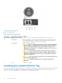
Locating your system Service Tag
Your system is identified by a unique Express Service Code and Service Tag number. The Express Service Code and Service Tag are found
on the front of the system by pulling out the information tag. Alternatively, the information may be on a sticker on the chassis of the
system. This information is used by Dell to route support calls to the appropriate personnel.
16
About your system

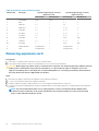
Documentation resources
This section provides information about the documentation resources for your system.
Task Document Location
Setting up your system For information about installing the system into a
rack, see the Rack documentation included with
your rack solution.
www.dell.com/storagemanuals
. For information about setting up your system, see
the Getting Started Guide document that is
shipped with your system
Configuring your system For information about configuring, managing,
updating, and restoring the system, see the Dell
EMC Network Attached Storage System using
Windows Storage Server 2016 Administrator's
Guide.
www.dell.com/storagemanuals
For information about the iDRAC features,
configuring and logging in to iDRAC, and managing
your system remotely, see the Integrated Dell
Remote Access Controller User's Guide.
www.dell.com/idracmanuals
For information about understanding Remote
Access Controller Admin (RACADM)
subcommands and supported RACADM interfaces,
see the RACADM Command Line Reference Guide
for iDRAC.
www.dell.com/idracmanuals
For information about updating drivers and
firmware.
www.dell.com/support/drivers
Managing your system For information about the features of the Dell
OpenManage Systems Management, see the Dell
OpenManage Systems Management Overview
Guide.
www.dell.com/
openmanagemanuals>OpenManage Essentials
For information about setting up, using, and
troubleshooting OpenManage, see the Dell
OpenManage Server Administrator User’s Guide.
www.dell.com/
openmanagemanuals>OpenManage Server
Administrator
For information about installing, using, and
troubleshooting Dell OpenManage Essentials, see
the Dell OpenManage Essentials User’s Guide.
www.dell.com/
openmanagemanuals>OpenManage Essentials
For information about installing and using Dell
SupportAssist, see the Dell EMC SupportAssist
Enterprise User's Guide.
www.dell.com/serviceabilitytools
For understanding the features of Dell Lifecycle
Controller, see the Dell Lifecycle Controller User’s
Guide.
www.dell.com/idracmanuals
For information about enterprise systems
management partner programs, see the
OpenManage Connections Enterprise Systems
Management documents.
www.dell.com/openmanagemanuals
For information about connections and client
systems management, see the OpenManage
Connections Client Systems Management
documentation.
www.dell.com/dellclientcommandsuitemanuals
2
Documentation resources 17

Task Document Location
Working with the Dell EMC
PowerEdge RAID controllers
For information about understanding the features
of the Dell PowerEdge RAID controllers (PERC)
and deploying the PERC cards, see the Storage
controller documentation.
www.dell.com/storagecontrollermanuals
Understanding event and error
messages
For information about the event and error
messages that are generated by the system
firmware and agents that monitor system
components, see the Error Code Lookup.
www.dell.com/qrl
Troubleshooting your system For information about troubleshooting the
hardware issues, see the Dell EMC Network
Attached Storage Systems using Windows
Storage Server 2016 Troubleshooting Guide.
www.dell.com/storagemanuals
18 Documentation resources

Technical specifications
Table 11. Processor specification
Processor
Processor type Two Intel Haswell processor E5-2600 v3 product family
Table 12. Expansion bus specification
Expansion Bus
Bus type PCIe Generation 3
Expansion cards For a list of supported expansion cards, see the Expansion card
installation guidelines section in this document.
Expansion slots using riser card:
Riser 1 (Slot 1) One half-height, three fourth-length x8 link
(Slot 2) One half-height, half-length x16 link
Riser 2 (Slot 1) One half-height, half-length x8 link or one half-height,
half-length x8 link
NOTE: Both processors must be installed to use the
slots on riser 1 and the x16 link on riser 2.
(Slot 2) One half-height, half-length x8 link or one half-height,
half-length x16 link
Riser 3 (Slot 2) One half-height, half-length x8 link or one half-height,
half-length x16 link
Table 13. Power specification
Power
AC PSU (per PSU)
Wattage 750 W
Heat dissipation
NOTE: Heat dissipation is calculated using the PSU
wattage rating.
2891 BTU/hr maximum (750 W PSU)
2843 BTU/hr maximum (750 W Titanium PSU)
Voltage
NOTE: This system is also designed to be connected to
IT power systems with a phase to phase voltage not
exceeding 230 V.
100–240 V AC, autoranging, 50/60 Hz
Or
200–240 V AC, autoranging, 50/60 Hz, for 750 W Titanium PSU
Table 14. Memory specification
Memory
Architecture 1866 MT/ and 2133 MT/s registered Error Correcting Code
(ECC) DIMMs
Support for Advanced ECC or memory-optimized operation
Support for LRDIMMs
Memory module sockets Twenty-four 288-pin
Memory module capacities
3
Technical specifications 19

Table 14. Memory specification (continued)
Memory
LRDIMM 4 GB, 8 GB, 16 GB, or 32 GB single-, dual-, or quad-ranked
RDIMM 4 GB, 8 GB, or 32 GB single-, dual-, or quad-ranked
16 GB single- or dual-ranked
Minimum RAM 2 GB with a single processor
4 GB with two processors
Maximum RAM
LRDIMM Up to 768 GB
RDIMM Up to 512 GB
Table 15. Drive specification
Drives
HDDs
8—HDD systems Up to eight 2.5 inch, internal, hot-swappable SAS, SATA, or
Nearline SAS HDDs
Optical drive One optional SATA DVD-ROM drive or DVD+/-RW drive
NOTE: DVD devices are data only.
Table 16. Connector specification
Connectors
Back
NIC Four 10/100/1000 Mbps or two 10/100/1000 Mbps and two 100
Mbps/1 Gbps/10 Gbps
Serial DB-9 Serial Port connector
USB Two 4-pin, USB 3.0-compliant
Video 15-pin VGA
Front
8 HDD systems
USB Two 4-pin, USB 3.0-compliant
Video 15-pin VGA
External vFlash card vFlash memory card slot
NOTE: The card slot is available for use only if the
iDRAC8 Enterprise license is installed on your system.
Internal
USB One 4-pin, USB 3.0-compliant
Internal Dual SD Module (IDSDM) Two optional flash memory card slots with the internal SD module
NOTE: One card slot is dedicated for redundancy.
Table 17. Video specification
Video
Video type Integrated VGA controller
Video memory 16 MB shared
20 Technical specifications
Page is loading ...
Page is loading ...
Page is loading ...
Page is loading ...
Page is loading ...
Page is loading ...
Page is loading ...
Page is loading ...
Page is loading ...
Page is loading ...
Page is loading ...
Page is loading ...
Page is loading ...
Page is loading ...
Page is loading ...
Page is loading ...
Page is loading ...
Page is loading ...
Page is loading ...
Page is loading ...
Page is loading ...
Page is loading ...
Page is loading ...
Page is loading ...
Page is loading ...
Page is loading ...
Page is loading ...
Page is loading ...
Page is loading ...
Page is loading ...
Page is loading ...
Page is loading ...
Page is loading ...
Page is loading ...
Page is loading ...
Page is loading ...
Page is loading ...
Page is loading ...
Page is loading ...
Page is loading ...
Page is loading ...
Page is loading ...
Page is loading ...
Page is loading ...
Page is loading ...
Page is loading ...
Page is loading ...
Page is loading ...
Page is loading ...
Page is loading ...
Page is loading ...
Page is loading ...
Page is loading ...
Page is loading ...
Page is loading ...
Page is loading ...
Page is loading ...
Page is loading ...
Page is loading ...
Page is loading ...
Page is loading ...
Page is loading ...
Page is loading ...
Page is loading ...
Page is loading ...
Page is loading ...
Page is loading ...
Page is loading ...
Page is loading ...
Page is loading ...
Page is loading ...
Page is loading ...
Page is loading ...
Page is loading ...
Page is loading ...
Page is loading ...
Page is loading ...
Page is loading ...
Page is loading ...
Page is loading ...
Page is loading ...
Page is loading ...
Page is loading ...
Page is loading ...
Page is loading ...
Page is loading ...
Page is loading ...
Page is loading ...
Page is loading ...
Page is loading ...
Page is loading ...
Page is loading ...
Page is loading ...
Page is loading ...
Page is loading ...
Page is loading ...
Page is loading ...
Page is loading ...
Page is loading ...
Page is loading ...
Page is loading ...
Page is loading ...
Page is loading ...
Page is loading ...
Page is loading ...
Page is loading ...
Page is loading ...
Page is loading ...
-
 1
1
-
 2
2
-
 3
3
-
 4
4
-
 5
5
-
 6
6
-
 7
7
-
 8
8
-
 9
9
-
 10
10
-
 11
11
-
 12
12
-
 13
13
-
 14
14
-
 15
15
-
 16
16
-
 17
17
-
 18
18
-
 19
19
-
 20
20
-
 21
21
-
 22
22
-
 23
23
-
 24
24
-
 25
25
-
 26
26
-
 27
27
-
 28
28
-
 29
29
-
 30
30
-
 31
31
-
 32
32
-
 33
33
-
 34
34
-
 35
35
-
 36
36
-
 37
37
-
 38
38
-
 39
39
-
 40
40
-
 41
41
-
 42
42
-
 43
43
-
 44
44
-
 45
45
-
 46
46
-
 47
47
-
 48
48
-
 49
49
-
 50
50
-
 51
51
-
 52
52
-
 53
53
-
 54
54
-
 55
55
-
 56
56
-
 57
57
-
 58
58
-
 59
59
-
 60
60
-
 61
61
-
 62
62
-
 63
63
-
 64
64
-
 65
65
-
 66
66
-
 67
67
-
 68
68
-
 69
69
-
 70
70
-
 71
71
-
 72
72
-
 73
73
-
 74
74
-
 75
75
-
 76
76
-
 77
77
-
 78
78
-
 79
79
-
 80
80
-
 81
81
-
 82
82
-
 83
83
-
 84
84
-
 85
85
-
 86
86
-
 87
87
-
 88
88
-
 89
89
-
 90
90
-
 91
91
-
 92
92
-
 93
93
-
 94
94
-
 95
95
-
 96
96
-
 97
97
-
 98
98
-
 99
99
-
 100
100
-
 101
101
-
 102
102
-
 103
103
-
 104
104
-
 105
105
-
 106
106
-
 107
107
-
 108
108
-
 109
109
-
 110
110
-
 111
111
-
 112
112
-
 113
113
-
 114
114
-
 115
115
-
 116
116
-
 117
117
-
 118
118
-
 119
119
-
 120
120
-
 121
121
-
 122
122
-
 123
123
-
 124
124
-
 125
125
-
 126
126
-
 127
127
-
 128
128


Dell Storage NX3330 Owner's manual
- Category
- Servers
- Type
- Owner's manual
Ask a question and I''ll find the answer in the document
Finding information in a document is now easier with AI
Related papers
-
Dell Storage NX3330 Owner's manual
-
Dell Life Jacket E23S Series User manual
-
Dell DL4000 Owner's manual
-
Dell Precision Rack 7910 Owner's manual
-
Dell PowerEdge R420xr User manual
-
Dell PowerVault NX3300 Owner's manual
-
-
Dell Storage NX3230 Owner's manual
-
-