Page is loading ...

DESIGNED & DEVELOPED
IN ITALY
MANUALE D’USO - Sezione 1
USER MANUAL - Section 1
BEDIENUNGSANLEITUNG - Abschnitt 1
CARACTERISTIQUES TECHNIQUES - Section 1
Le avvertenze nel presente manuale devono essere osservate congiuntamente al “MANUALE D’USO - Sezione2”.
The warnings in this manual must be observed together with the "USER MANUAL - Section 2".
Die Warnungen in diesem Handbuch müssen in Verbindung mit der "BEDIENUNGSANLEITUNG - Abschnitt 2" beobachtet werden.
Les avertissements dans ce manuel doivent être respectées en collaboration avec le "CARATTERISTIQUES TECHNIQUES - Section 2".
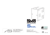
DVA MS12

DVA MINI Digital Array System
7
ENGLISH
DESCRIPTION
The speaker DVA MS12 is part of the modular system called DVA MINI.
The system can be used in ground stack configuration or suspended in line-array configuration.
The modules use a fast, innovative mechanical fastening method.
This series is ideal for installations in theatres, places of worship, convention centers, concerts and
live music performances which require medium-high sound pressures and limited weight and
footprint.
DVA MS12 is equipped with a class-D amplifier series DIGIPRO
®
G3 capable of delivering 700W PMS and is equipped with a 12"
woofer (voice coil 3").
The high efficiency of the modules DIGIPRO
®
G3 allows to obtain high output power, with reduced
weight and footprint. Thanks to its low power dissipation, the cooling of the amplifier module takes
place in a static manner, avoiding the use of fans.
The digital pre-amplifier with Digital Signal Processor (DSP) manages the acoustic components,
the frequency response, the limiter and the speaker alerts.
The SMPS (Switched-Mode Power Supply) Power Supply Unit (PSU) thanks to its self-range
technology ensures operation at supply voltages from 100V~ to 120V~ and from 220V~ to 240V~.
The subwoofer is in multi-layer birch wood with two side handles that
facilitate its transport and installation. The speaker is equipped with a
support with M20 thread for fastening with D35mm pole.
The speaker is fitted with steel brackets and a handy locking system for
fastening the various elements of the DVA MINI system.
The four feet in plastics in the lower part of the speaker have a dual
position:
- external: for use as support, protecting the brackets from
damage due to impacts with the ground.
- retractable: for suspended use, so as to ensure the correct
mechanical coupling with the other elements of the array.
A tilt angle is guaranteed by means of a graduated bracket on the rear of the box (0°-1.5°-3°-4.5°-
6°-8°) to allow the fastening of the different speakers with the desired angle.
The only angle allowed between the subwoofer DVA MS12 is 0°; the angles allowed between DVA
MS12 and DVA M2M/DVA M2S are 0°-1.5°-3°-4.5°-6°-8°.

8
ENGLISH
Functions and controls
"Balanced Audio Input" section
1) " INPUT” INPUT CONNECTOR
Audio balanced input at line level. It is able to accept “XLR” sockets.
"Balanced Subwoofer Output & configuration" section
2) “Output” OUTPUT CONNECTOR
The "XLR" connector can be used to send the audio signal in input to another amplified
speaker.
It is possible to set the type of signal to be redirected using the selector "Xover" (3) and
"Output Mode" (4)
3) "Xover" SELECTOR
This selector allows to select the crossover frequency between the subwoofer and the
speaker connected to it through the "Output" output (2)
The crossover frequency can be set at 110Hz or 140Hz.
The choice of the crossover frequency depends on the desired sound reproduction.
4) "Output Mode" SELECTOR
This switch allows to select the signal to be redirected to the "Output" output (2).
The "Link" position allows to redirect the same signal received at the "Input" input (1).
The "Xover" position allows to send the input signal cut at the crossover frequency selected by
means of the selector "Xover" (3).
"Status" section
5) “LIMITER” INDICATOR LIGHT
This indicator comes on red to indicate that the internal limiter circuit has tripped.
This prevents amplifier distortion and protects the speakers against overloads.
Always avoid operating conditions where the system works for long periods of time
with LED flashes or it is always ON
6) “SIGNAL” INDICATOR LIGHT
This indicator comes on green to indicate the presence of an input signal to a level higher
than -20dBu.
7) “MUTE/PROT” INDICATOR LIGHT
This yellow indicator indicates amplifier status. In normal operating conditions, the LED is off;
if it flashes or is always on, refer to the diagnostics table to check amplifier status.
8) “READY” INDICATOR LIGHT
This indicator comes on green to indicate that the main power voltage is correct. In normal
operating conditions, the LED is on; if it flashes or is off, refer to the diagnostics table.
"Service" section
9) “Service Data USB” Connector
Via this USB connector, it is possible to update the firmware of the DVA MS12 amplifier
module using the computer and a dedicated program.
"Subwoofer level " section
10) “Input Sensitivity” INPUT SENSITIVITY CONTROL
This control regulates the sensitivity of the signal amplifier input .
It does not affect the “Output” (2) level

DVA MINI Digital Array System
9
ENGLISH
"Subwoofer Phase " section
11) “Phase” switch
This two-position switch permits turning the audio signal reproduced by the subwoofer by
180°.
Rotation makes it easier to optimize the reproduction of the low frequencies even in the most
difficult installation situations. After completing installation, play a piece of music and move the
switch to achieve the best sound reproduction at low frequencies.
Power supply section
12) "AUTO-RANGE” MAINS INPUT" POWER SOCKET
For connecting the power cable.
The connector used for mains connection is a POWER CON® (blue)
13) “MAINS OUTPUT LINK” RELAUNCH POWER SOCKET
For re-launching the mains power. The output is connected in parallel with input (11) and can
be used to power another amplified speaker.
The connector uses a POWER CON® (grey)
14) "MAINS FUSE" FUSE CARRIER
Mains fuse housing.

10
ENGLISH
CHARACTERISTICS AND PROTECTION
Indications of operation model, malfunction, and safeties
The light indicators (LEDs) "READY", "MUTE/PROT", "SIGNAL" and "LIMIT" are also used to
indicate different modes of operation and different types of faults, by flashing sequences as
reported in the diagnostics table below.
The three types of failure are:
- WARNING: a non-severe error or auto-reset malfunction is detected and the performance of
the speaker is not limited
- LIMITATION: an error is detected and diffuser performance is limited. The sound level is
reduced or one or more amplifiers are disabled. This state partially influences the correct
functioning of the diffuser. If the problem persists the next time the module is turned on,
contact the support center for assistance.
- FAILURE: a severe malfunction is detected. The speaker switches to “mute”.
If the case of a malfunction, before contacting the support center, try to turn the module off and on
to check if the problem still exists.
Cooling
The cooling of the amplifier is realized by convection on internal/external heat sinks without the aid
of fans
.
Thermal protection is ensured by an internal circuit which controls the temperature of the amplifier
and protects it from overheating by limiting the overall volume.
This intervention is marked by the flashing of a yellow indicator light "MUTE/PROT".
The correct volume and all the functions will be automatically restarted after normal operating
temperatures have been restored.
Protection
When the yellow “MUTE/PROT” LED turns on, it means that a malfunction has been detected on
the speaker, thus setting this to the mute position.
Perform the checks listed below:
- Check if the speaker is properly connected to the power supply.
- Make sure that the power supply is of correct voltage.
- Check that the amplifier is not overheated.
- Disconnect the speaker from the mains power supply, wait for a few minutes and connect
it again.
If after these tests the LED is still on, please contact an authorized service center.
DIAGNOSTICS TABLE
STATE OR
CONDITION OF THE
MODULE
LED
“READY”
LED
“MUTE/PROT”
LED
“SIGNAL”
LED
“LIMITER”
FUNCTIONS OR DESCRIPTION OF THE
MODULE
Normal operation
Power ON
OFF
ON for 5 sec.
OFF
OFF
Audio MUTED
Initialization of the amplifier module
Normal use
ON
OFF
Normal
operation
Normal
operation
Audio ACTIVE
Module initialization complete and correct
Partial fault
ON
Cycling
flashing (quick
flashes)
Normal
operation
Normal
operation
Audio ACTIVE
The module has detected a partial anomaly
and remains active with limited functions
Total fault
OFF
ON
OFF
Cycling
flashing (quick
flashes)
Audio MUTED
The module has detected a serious anomaly
and is in protected mode

DVA MINI Digital Array System
11
ENGLISH
STATE OR
CONDITION OF THE
MODULE
LED
“READY”
LED
“MUTE/PROT”
LED
“SIGNAL”
LED
“LIMITER”
FUNCTIONS OR
DESCRIPTION OF THE
MODULE
Amplifier temperature management
Amplifier temperature
(thermal threshold)
Normal
operation
Cycling
flashing
Normal
operation
Normal
operation
Audio ACTIVE
The amplifier module reduces the volume, in
steps of 0.1 dBm up to a maximum of 6dBm,
as the temperature rises above the safety
threshold.
Generic errors
No power supply (Vac)
detected
OFF
ON
OFF
OFF
A momentary lack of supply voltage is
detected during normal operation
Current overload
OFF
ON
OFF
ON
A
current overload is detected during normal
operation.
Communication error
with the DSP
OFF
ON
OFF
Cyclic flashing
(1slow flashes)
A communication error between the
preamplifier and the processor of the audio
signal has been detected.
Incorrect
configuration
OFF
ON
OFF
Cyclic flashing
(2slow flashes)
The settings of the amplifier module do not
match the hardware configuration of the
module.
Incorrect firmware
OFF
ON
OFF
Cyclic flashing
(3slow flashes)
The DSP firmware does not match the versi
on
of the pre-amplifier
USB Mode
Bootloader function
ON
OFF
OFF
They flash alternately
The bootloader function in the pre
-
amplifier is
active
Telemetry ON
They flash alternately
OFF
OFF
The amplifier module is connected to the USB
port for downloading the telemetry
CONNECTIONS
USB Data Link
The speaker DVA MS12 is equipped with a USB "Service" connector, useful for the firmware
update of the module or to download speaker operation data.
Connecting to the mains supply
Each active speaker features its own power cable. Connection is done by a Neutrik POWER
CON® (Blue) model which permits easy and fast connection to the speaker as well as being an
excellent locking system.
The POWER CON connector acts as the disconnecting device for the power supply and must be
easily accessible after installation and during use of the speaker
The active speaker must be connected to a power supply able to deliver the maximum required
power.
The DVA MS12 is provide on its own power cord.
Main power supply linking
On the rear of the speaker, a Neutrik POWER CON® connector (Grey) offers linking the mains
power supply.
This socket links the power supply to another speaker, thereby reducing the direct connections to
the mains. Maximum amplifier input power is shown on the amplifier panel.
The maximum number of speakers connected to the LINK OUT connector varies depending on the
voltage of power supply used and the type of connected speaker to this socket. Do not exceed in
any case the maximum current / power specified in the data on the panel. This failure can cause
overheating and damage to the products.

12
ENGLISH
TECHNICAL SPECIFICATION
DVA MS12
System
Active Amps
Type of amplifier
Digital
–
Class D
DIGIPRO G3
TM
technology
RMS power
700W
Musical power
14
00W
Frequency response (
-
6dB)
(-10dB)
45Hz
-
140
Hz
40Hz-165Hz
Cover range
Omnidirectional
Sound pressure (SPL)
131
dB
Component parts
1 woofer 12”
–
VC 3”
Input sensitivity nominal
0dB
Input impendence
Balanced
Unbalanced
20Kohm
10Kohm
Power supply
Auto
-
Range
100-120Vac 50-60Hz
220-240Vac 50-60Hz
Inrush current
17.9
A
Current consumption
100-120Vac 50-60Hz
220-240Vac 50-60Hz
4A
2A
Dimensions (LxHxP)
460x430x38
5mm
18.1x16.9x15.2 inch.
Weight
26.2
Kg
58.4lbs
DSP processor
DSP
Audio conversion AD/DA
Volume control
Crossover (24dB/Oct)
28/56bit
24bit/48KHz
Digital
110Hz/140Hz
Mechanical parts
Box material
Colour
Box internal reinforcement
Housing shape
Stirrup material
Handle
Frontal grille
Birch plywood
Black
Birch plywood
Rectangular
Steel
1 x each side
Performed sheet 1.5mm
with internal foam
EMI CLASSIFICATION
According to the standards EN 55103 this equipment is designed and suitable to operate in E3 (or
lower E2, E1) Electromagnetic environments.

DVA MINI Digital Array System
25
DVA USB Manager
Il firmware del modulo amplificatore può essere aggiornato tramite la porta USB.
Per rendere possibile e facile questo aggiornamento è stato sviluppato un programma dedicato.
Si raccomanda di scaricare il software gratuito DVA USB Manager direttamente dal sito
dB Technologies (www.dbtechnologies.com) nella sezione dedicata “Software &
Controller”
DVA Composer - Simulazione acustica di sistemi serie DVA
DVA Composer è un software di puntamento e simulazione acustica per tutti i modelli Line Array
della serie DVA e relativi Subwoofers.
Tale software permette di gestire un sistema stereo composto da line array e subwoofer,
simulandone separatamente la risposta acustica di entrambi
Vengono inoltre fornite all'utente una serie di informazioni quali: allineamento in fase tra i sistemi
sospesi e i relativi subwoofer a terra; vengono suggeriti gli angoli ottimali tra i moduli che
compongono i line array e i relativi preset di equalizzazione da assegnare, al fine di consentire
anche ad utenti non esperti di ottimizzare le performance del sistema.
Si raccomanda di scaricare gratuitamente il software DVA_Composer direttamente dal
sito dB Technologies (www.dbtechnologies.com) nella sezione dedicata «Software &
Controller»
DVA USB Manager
The firmware of the amplifier module can be updated via the USB port.
To make this update possible and simple, a dedicated program has been developed.
It is recommended to download DVA USB Manager free software directly from dB
Technologies (www.dbtechnologies.com) in the special section «Software & Controller»
DVA Composer Acoustical Simulation and aiming for DVA Systems
DVA Composer is a software for aiming and simulating acoustical response of all line arrays and
Subwoofers from DVA Series.
The software allows you to set up a stereo system composed by tops and subs, and simulates
separately the acoustical response of both
DVA Composer also gives to the user all the information about phase alignment between flown
systems and ground stacked subwoofers, as well as it suggests an optimized aiming of the line
arrays modules and their suggested EQ presets, in order to guarantee maximum performances
even for non-expert customers.
It is recommended to download DVA_Composer free software directly from dB
Technologies (www.dbtechnologies.com) in the special section «Software & Controller»
ENGLISH
ITALIANO

28
INSTALLAZIONE - INSTALLATION

DVA MINI Digital Array System
29
INSTALLATIONEN - INSTALLATIONS
INDICAZIONE POSIZIONE DEL PERNO NELLA STAFFA POSTERIORE
INDICATION OF THE POSITION OF THE PIN IN THE REAR BRACKET
ANGABE DER POSITION DES ZAPFENS IM HINTEREN BÜGEL
INDICATION POSITION DE LA GOUPILLE SUR L'ETRIER POSTERIEUR
Posizione della staffa in blocco con angolazione desiderata
Position of the bracket in block with desired angle
Blockierungsposition des Bügels mit gewünschtem Winkel
Position de l'étrier bloqué avec disposition en angle désirée
ATTENZIONE
Se il perno NON è inserito all’interno del blocco, il
diffusore NON è bloccato
ATTENTION: If the pin is NOT inserted within the
block, the speaker is NOT locked
ACHTUNG : Wenn der Zapfen NICHT im Block
eingesetzt ist, ist der Lautsprecher NICHT blockiert
ATTENTION : Si la goupille N'est PAS insérée à
l'intérieur du blocage, le diffuseur N'est PAS bloqué
Verificare sempre il corretto inserimento del perno di blocco
per evitare movimenti pericolosi nel caso di fuoriuscita del
perno di stazionamento.
Always check the correct insertion of the lock pin to avoid
dangerous movements in case of release of the parking pin
Immer den korrekten Sitz des Blockierungszapfens prüfen,
um gefährliche Bewegungen beim Heraustreten des
Haltezapfens zu vermeiden.
Toujours vérifier la correcte insertion de la goupille de blocage
pour éviter des mouvements dangereux en cas de sortie de la
goupille de retenue

30
UNIONE DVA MS12 - DVA M2M/DVA M2S
COMBINATION DVA MS12 - DVA M2M/DVA M2S
KOMBINATION DVA MS12 - DVA M2M/DVA M2S
COMBINAISON
DVA
MS12
-
DVA
M2M/DVA
M2S
La posizione dei diffusori è indicativa
The position of the speakers is indicative
Die Position der beiden Lautsprecher Indikativ
La position des haut-parleurs est indicatif

DVA MINI Digital Array System
31

32
La leva Rossa deve essere posizionata come
indicato in figura per garantire il bloccaggio dei
diffusori
The Red lever must be positioned as shown in
the figure to ensure the locking of the speakers
Der rote Hebel muss wie in Abbildung
positioniert sein, um die Blockierung der
Lautsprecher zu garantieren
Le levier Rouge doit être positionné comme
indiqué sur la figure pour garantir le blocage des
diffuseurs

DVA MINI Digital Array System
33

DVA MINI Digital Array System
35
Bloccare la staffa con il pin in uno dei due
fori indicati in figura
Lock the bracket with the pin in one of the
two holes indicated in the figure
Den Bügel mit dem Zapfen in einem der
beiden Öffnungen, die in Abbildung gezeigt
werden, blockieren
Bloquer l'étrier avec la goupille dans l'un des
deux orifices indiqués sur la figure

36
------------------------------------------------------------------------
ISTRUZIONI DI SICUREZZA PER ACCESSORI
SAFETY INSTRUCTIONS FOR ACCESSORIES
ZUBEHÖR SICHERHEITSHINWEISE
INSTRUCTIONS DE SÉCURITÉ POUR LES ACCESSOIRES
Per un corretto utilizzo in sicurezza del sistema DVA MINI e al fine di evitare pericoli di ribaltamento e danni a persone, animali e cose,
prima di procedere all'installazione del sistema, verificare sul sito dBTechnologies le configurazioni ammissibili, le indicazioni previste e le
relative prescrizioni di sicurezza. Utilizzare solo parti originali fornite da dBTechnologies.
Si declina ogni responsabilità da un utilizzo inappropriato degli accessori o di dispositivi aggiuntivi non idonei allo scopo.
Conservare ed archiviare tutti i documenti del sistema DVA MINI in un posto sicuro per successive consultazioni.
Installare il diffusore in modo stabile e sicuro, così da evitare qualsiasi condizione di pericolo per l’incolumità di persone e strutture.
Ogni installazione ed utilizzo delle parti fornite come accessori deve essere eseguita in accordo alle istruzioni di montaggio a corredo
dell’accessorio stesso.
For proper and safe use of the system DVA MINI and in order to avoid any risk of overturning and injuries to persons, animals and
property, before to proceed to the system installation, check the dBTechnologies allowable configurations, the particulars provided and
related safety requirements. Use only dB Technologies original parts.
Will not accept any responsibility when inappropriate accessories or not suitable additional devices are used.
Compile and store all DVA MINI system documents in a safe place for future reference.
Make sure that the loudspeaker is securely installed in a stable position to avoid any injuries or damages to persons or property.
Always install parts in accordance with these installation instruction!
Für die ordnungsgemäße und sichere Nutzung des Systems DVA MINI und um jegliche Kippgefahr und Verletzungen von Personen,
Tieren und Sachen, zu vermeiden, bevor auf das System mit der Installation fortfahren, überprüfen der dBTechnologies zulässigen
Konfigurationen, die Angaben zur Verfügung gestellt und damit verbundenen Sicherheitsanforderungen. Nur Original-Teile von
dBTechnologies verwenden.
Falls unpassendes Zubehör verwendet wird, wird jegliche Haftung ausgeschlossen.
Alle Unterlagen des Systems DVA MINI müssen an einem sicheren Ort aufbewahrt waschen für die Zukunft.
Den Lautsprecher auf eine stabile und sichere Art und Weise installieren, um jede Gefahr für Personen oder Sachschäden zu vermeiden.
Jede Installation oder Benutzung der gelieferten Teile muss entsprechend der mitgelieferten Montageanleitung ausgeführt werden.
Pour une utilisation correcte et sûre du système DVA MINI et afin d'éviter tout risque de renversement et les blessures aux personnes,
aux animaux et des biens, avant de procéder à l'installation du système, vérifiez les dBTechnologies configurations admissibles, les
indications prévues et les exigences de sécurité connexes. N'utiliser que les pièces originales fournies par dBTechnologies.
N'accepterons pas toutes les responsabilités lorsque des accessoires inappropriés ou ne conviennent as à des dispositifs
supplémentaires sont utilisés.
Conserver et mettre aux archives en un lieu sûr tous les documents du système DVA MINI pour référence future!
Installer le diffuseur de façon stable et sûre afin d'éviter toute condition de danger pour l'intégrité des personnes et des structures.
Toute installation et utilisation des pièces fournies doit être exécutée conformément aux instructions de montage qui accompagnent le
dispositif.
AVVERTENZA – WARNING – ACHTUNG - ATTENTION
Prima si sospendere il diffusore controllare tutti i componenti da utilizzare (non devono presentare danni, deformazioni, parti
mancanti o danneggiate che possono ridurre la sicurezza dell’installazione).
Before hanging the loudspeaker check all the components for damages, deformations, missing or damaged parts that may
compromise safety during installation.
Bevor man den Lautsprecher aufhängt, alle Teile kontrollieren, sie sollen keine Schäden oder Verformungen, keine fehlenden
oder beschädigten Teile haben, die eine sichere Installation beeinträchtigen könnten.
Avant de suspendre le diffuseur, contrôler tous les composants à utiliser, qui ne doivent présenter aucun dommage, aucune
déformation ou partie manquante ou abimée qui seraient susceptibles de réduire la sécurité de l'installation.

38
ACCESSORIO DGS-MS12 (adattatore per ancoarggio a terra subwoofer)
ACCESSORY DSA-M2 (adaptor for fasten in place subwoofer on ground)
Per le istruzioni di assemblaggio fare riferimento al manuale dedicato incluso nell’accessorio.
For assembly instructions refer to the included manual dedicated accessory.
ACCESSORIO RC-MS12 (Protezione pioggia per modulo connettori )
ACCESSORY RC-MS12 (Rain cover protection for connectors module)
Per le istruzioni di assemblaggio fare riferimento al manuale dedicato incluso nell’accessorio.
For assembly instructions refer to the included manual dedicated accessory.

DVA MINI Digital Array System
39
A.E.B. Industriale Srl
Via Brodolini, 8
Località Crespellano
40053 VALSAMOGGIA
BOLOGNA (ITALIA)
Tel +39 051 969870
Fax +39 051 969725
www.dbtechnologies.com
info@dbtechnologies-aeb.com
Codice 420120215 Rev 1.0
/