Gigabyte GA-8I915G Duo User manual
- Category
- Motherboards
- Type
- User manual
This manual is also suitable for

GA-8I915G Pro
Intel
®
Pentium
®
4 LGA775 Processor Motherboard
User's Manual
Rev. 1002
12ME-8I915GP-1002

Motherboard
GA-8I915G Pro
Jun. 11, 2004
Jun.11, 2004
Motherboard
GA-8I915G Pro

Copyright
© 2004 GIGA-BYTE TECHNOLOGY CO., LTD. All rights reserved.
The trademarks mentioned in the manual are legally registered to their respective companies.
Notice
The written content provided with this product is the property of Gigabyte.
No part of this manual may be reproduced, copied, translated, or transmitted in any form or by any
means without Gigabyte's prior written permission. Specifications and features are subject to
change without prior notice.
Product Manual Classification
In order to assist in the use of this product, Gigabyte has categorized the user manual in the
following:
n For quick installation, please refer to the "Hardware Installation Guide" included with the
product.
n For detailed product information and specifications, please carefully read the
"Product User Manual".
n For detailed information related to Gigabyte's unique features, please go to Gigabyte's
website under "Technology Guide" where information can be downloaded in .pdf format.
Fore more product details, please click onto Gigabyte's website at www.gigabyte.com.tw

- 4 -
Table of Contents
GA-8I915G Pro Motherboard Layout ..........................................................................6
Block Diagram ...........................................................................................................7
Chapter 1 Hardware Installation ..................................................................................9
1-1 Considerations Prior to Installation ......................................................................... 9
1-2 Feature Summary .................................................................................................10
1-3 Installation of the CPU and Heatsink ...................................................................12
1-3-1 Installation of the CPU .................................................................................... 12
1-3-2 Installation of the Heatsink .............................................................................. 13
1-4 Installation of Memory...........................................................................................14
1-5 Install expansion cards .........................................................................................16
1-6 I/O Back Panel Introduction .................................................................................17
1-7 Connectors Introduction ........................................................................................18
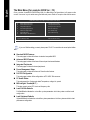
Chapter 2 BIOS Setup ............................................................................................ 29
The Main Menu (For example: BIOS Ver. : F3) ............................................................30
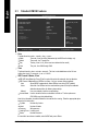
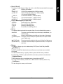
2-1 Standard CMOS Features ...................................................................................32
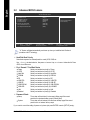
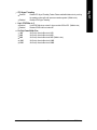
2-2 Advanced BIOS Features ....................................................................................34
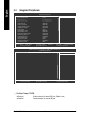
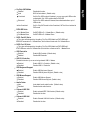
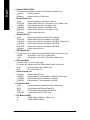
2-3 Integrated Peripherals ...........................................................................................36
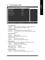
2-4 Power Management Setup ...................................................................................39
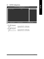
2-5 PnP/PCI Configurations .......................................................................................41
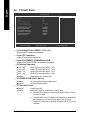
2-6 PC Health Status ..................................................................................................42
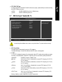
2-7 MB Intelligent Tweaker(M.I.T.) .............................................................................43
2-8 Load Fail-Safe Defaults .........................................................................................45
2-9 Load Optimized Defaults .......................................................................................45
2-10 Set Supervisor/User Password .......................................................................... 46
2-11 Save & Exit Setup ...............................................................................................47
2-12 Exit Without Saving .............................................................................................. 47
Chapter 3 Drivers Installation ................................................................................... 49
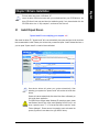
3-1 Install Chipset Drivers ..........................................................................................49
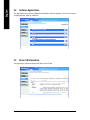
3-2 Software Applications ............................................................................................50
3-3 Driver CD Information ...........................................................................................50
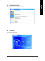
3-4 Hardware Information ...........................................................................................51
3-5 Contact Us ............................................................................................................51
Chapter 4 Appendix ............................................................................................... 55

- 5 -
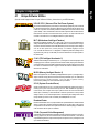
4-1 Unique Software Utilities ......................................................................................55
4-1-1 Xpress Recovery Introduction ....................................................................... 56
4-1-2 Flash BIOS Method Introduction .................................................................... 59
4-1-4 2 / 4 / 5.1 / 7.1 Channel Audio Function Introduction .................................. 70
4-2 Troubleshooting ......................................................................................................76

- 6 -
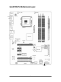
GA-8I915G Pro Motherboard Layout
KB_MS
ATX_12V
CPU_FAN
LGA775
AUDIO1
Intel 915G
PC IE_16
CODEC
F_U SB1
LPT
USB
IT8712
Intel IC H6
BACK
BIOS
PCIE_1
PCI2
F2_1394 F1_1394
AZALIA_FP
BAT
ATX
IDE
FDD
CD_IN
GA-8I915G Pro
PCI1
VGA
USB
LAN
DDR1
DDR2
DDR3
DDR4
F_U SB2
TSB43AB23
PWR_LED
F_PAN EL
SYS_FAN
CLR_CMOS
PWR_FAN
PCIE_3
PCIE_2
MAIN
BIOS
S_ATA4
S_ATA2
Marvell
8001
COMA
AUDIO2
S_ATA3
SPDIF_OUT
SPDIF_IN
IR
S_ATA1
NB_FAN

- 7 -
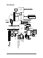
Block Diagram
LGA775
Processor
CPUCLK+/-(200/133MHz)
PCI Express x16
33MHz
Host
Interface
Intel
915G
GMCH
GMCHCLK (200/133MHz)
66MHz
48MHz
LPT Port
COM Port
Floppy
PS/2 KB/Mouse
24MHz
33MHz
IT 8712
4 Serial ATA
ATA33/66/100
IDE Channels
Intel
ICH6
3 PCI E xpressx 1 Ports
14.318MHz
Dual BIOS
8 USB
Ports
PCI Express x1 Bus
PCICLK
(33MHz)
2 PCI
PCI Bus
VGA
Line-Out
MIC
Surround Speaker Out
Center/Subwoofer Speaker Out
Back Surround Speaker Out
CODEC
Line-In
SPDIF In
SPDIF Out
3 IEEE1394
TSB43AB23
Marvell
8001
RJ45
DDR 400/333MHz DIMM
Dual Channel Memory
PCI-ECLK
(100MHz)
PCI-ECLK
(100MHz)

- 8 -

Hardware Installation- 9 -
English
1-1 Considerations Prior to Installation
Preparing Your Computer
The motherboard contains numerous delicate electronic circuits and components which can
become damaged as a result of electrostatic discharge (ESD). Thus, prior to installation, please
follow the instructions below:
1. Please turn off the computer and unplug its power cord.
2. When handling the motherboard, avoid touching any metal leads or connectors.
3. It is best to wear an electrostatic discharge (ESD) cuff when handling electronic components
(CPU, RAM).
4. Prior to installing the electronic components, please have these items on top of an antistatic pad or
within a electrostatic shielding container.
5. Please verify that you the power supply is switched off before unplugging the power supply connector
from the motherboard.
Installation Notices
1. Prior to installation, please do not remove the stickers on the motherboard. These stickers are required
for warranty validation.
2. Prior to the installation of the motherboard or any hardware, please first carefully read the information
in the provided manual.
3. Before using the product, please verify that all cables and power connectors are connected.
4. To prevent damage to the motherboard, please do not allow screws to come in contact with the
motherboard circuit or its components.
5. Please make sure there are no leftover screws or metal components placed on the motherboard or
within the computer casing.
6. Please do not place the computer system on an uneven surface.
7. Turning on the computer power during the installation process can lead to damage to system
components as well as physical harm to the user.
8. If you are uncertain about any installation steps or have a problem related to the use of the product,
please consult a certified computer technician.
Instances of Non-Warranty
1. Damage due to natural disaster, accident or human cause.
2. Damage as a result of violating the conditions recommended in the user manual.
3. Damage due to improper installation.
4. Damage due to use of uncertified components.
5. Damage due to use exceeding the permitted parameters.
6. Product determined to be an unofficial Gigabyte product.
Chapter 1 Hardware Installation

GA-8I915G Pro Motherboard - 10 -
English
CPU w Supports the latest Intel
®
Pentium
®
4 LGA775 CPU
w Supports 800/533MHz FSB
w L2 cache varies with CPU
Chipset w Northbridge: Intel
®
915G Express Chipset
w Southbridge: Intel
®
ICH6
Memory w 4 DDR DIMM memory slots (supports up to 4GB memory)
(Note 1)
w Supports dual channel DDR400/333 DIMM
w Supports 2.5V DDR DIMM
Slots w 1 PCI Express x 16 slot
w 3 PCI Express x 1 slots
w 2 PCI slots
IDE Connections w 1 IDE connection (UDMA 33/ATA 66/ATA 100), allows connection of 2
IDE devices
FDD Connections w 1 FDD connection, allows connection of 2 FDD devices
Onboard SATA w 4 Serial ATA connections
Peripherals w 1 parallel port supporting Normal/EPP/ECP mode
w 1 VGA port, onboard COMA connection
w 8 USB 2.0/1.1 ports (rear x 4, front x 4 via cable)
w 3 IEEE1394 ports (requires cable)
w 1 front audio connector
w 1 IR connector
w 1 PS/2 keyboard port
w 1 PS/2 mouse port
Onboard LAN w Onboard Marvell 8001 chip (10/100/1000 Mbit)
w 1 RJ 45 port
Onboard Audio w C-Media 9880 CODEC (UAJ)
w Supports Jack Sensing function
w Supports 2 / 4 / 5.1 / 7.1 channel audio
w Supports Line In ; Line Out ; MIC ; Back Surround Speaker Out ;
Center/Subwoofer Speaker Out ; Surround Speaker Out connection
w Supports SPDIF In/Out connection
w CD In
(Note 1) Due to standard PC architecture, a certain amount of memory is reserved for system usage and
therefore the actual memory size is less than the stated amount.
For example, 4 GB of memory size will instead be shown as 3.xxGB memory during system startup.
1-2 Feature Summary

Hardware Installation- 11 -
English
I/O Control w IT8712
Hardware Monitor w CPU / System / Power fan speed detection
w CPU temperature detection
w System voltage detection
w CPU / System / Power fan failure warning
w CPU Smart FAN Control
BIOS w Use of licensed AWARD BIOS
w Supports Dual BIOS/Q-Flash
Additional Features w Supports @BIOS
w Supports EasyTune
Overclocking w Over Voltage via BIOS (CPU/DDR/PCI-E)
w Over Clock via BIOS (CPU/DDR)
Form Factor w ATX form factor; 30.5cm x 24.4cm

GA-8I915G Pro Motherboard - 12 -
English
1-3 Installation of the CPU and Heatsink
Before installing the CPU, please comply with the following conditions:
1. Please make sure that the motherboard supports the CPU.
2. Please take note of the one indented corner of the CPU. If you install the CPU in the wrong
direction, the CPU will not insert properly. If this occurs, please change the insert direction
of the CPU.
3. Please add an even layer of heat sink paste between the CPU and heatsink.
4. Please make sure the heatsink is installed on the CPU prior to system use, otherwise
overheating and permanent damage of the CPU may occur.
5. Please set the CPU host frequency in accordance with the processor specifications. It is not
recommended that the system bus frequency be set beyond hardware specifications since it
does not meet the required standards for the peripherals. If you wish to set the frequency
beyond the proper specifications, please do so according to your hardware specifications
including the CPU, graphics card, mem ory, hard drive, etc.
HT functionality requirement content :
Enabling the functionality of Hyper-Threading Technology for your computer system requires all
of the following platform components:
- CPU: An Intel
®
Pentium 4 Processor with HT Technology
- Chipset: An Intel
®
Chipset that supports HT Technology
- BIOS: A BIOS that supports HT Technology and has it enabled
- OS: An operation system that has optimizations for HT Technology
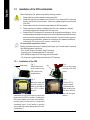
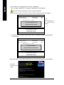
1-3-1 Installation of the CPU
Fig. 1
Gently lift the metal
lever located on the
CPU socket to the
upright position.
Metal Lever
Fig. 2
Rem ov e the pl astic
covering on the CPU
socket.
Fig. 3
Notice the sm all gold
color ed triangl e lo-
cated on the edge of
th e C P U s o c k e t.
Align the
Fig. 4
Once the CPU is
properly inserted,
please replace the
plastic covering and
push the m etal lever
back into its original
position.
indented corner of the CPU with the triangle and
gently insert the CPU into position. (Grasping the
CPU firm ly between your thum b and forefinger,
carefully place it into the socket in a straight and
downwards m otion. Avoid twisting or bending
motions that might cause damage to the CPU dur-
ing installation.)

Hardware Installation- 13 -
English
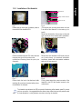
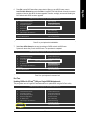
1-3-2 Installation of the Heatsink
Fig.1
Please apply an even layer of heatsink paste on
the surface of the installed CPU.
The heatsink may adhere to the CPU as a result of hardening of the heatsink paste.To prevent
such an occurrence, it is suggested that either thermal tape rather than heat sink paste be used
for heat dissipation or using extreme care when removing the heatsink.
Fig. 6
Finally, please attach the power connector of the
heatsink to the CPU fan header located on the
motherboard.
Fig. 3
Place the heatsink atop the CPU and m ake sure
the push pins aim to the pin hole on the
m otherboard.Pressing down the push pins
diagonally.
Fig. 2
(Turning the push pin along the direction of arrow
is to rem ove the heatsink, on the contrary, is to
install.)
Please note the direction of arrow sign on the m ale
push pin doesn't face inwards before installation.
(This instruction is only for Intel boxed fan)
Fig. 4
Please make sure the Male and Female push pin
are join ed cl osely . (fo r de tail ed i nsta llation
instructions, please refer to the heatsink installation
section of the user manual)
Fig. 5
Please check the back of m otherboard after
installing. If the push pin is inserted as the picture,
the installation is com plete.
Male Push Pin
Female Push Pin
The top of Female Push Pin

GA-8I915G Pro Motherboard - 14 -
English
Before installing the memory modules, please comply with the following conditions:
1 . Please make sure that the memory used is supported by the motherboard. It is recommended that
me mo ry o f si mi la r ca pa ci ty , spe ci fi ca ti on s an d br an d be u se d.
2 . Be fo re i ns ta ll in g or r em ov ing m em or y mo du le s, p le as e m ak e su re t ha t th e co mp ut er
p ow er i s s wi tc he d o ff t o p re ve nt ha rd wa re da ma ge .
3 . M em or y mo d ul es h av e a f oo lp r oo f in se r ti on d es i gn . A m e mo ry m od u le c an b e
ins talled in on ly on e dire ction . If you ar e una ble to inser t the modul e, pl ease s witch the
di re ct io n.
Notch
DDR
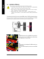
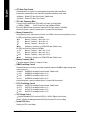
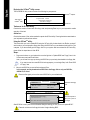
1-4 Installation of Memory
The m otherboard has 4 dual inline m emory module (DIMM) sockets. The BIOS will automatically detects
memory type and size. To install the memory module, just push it vertically into the DIMM socket. The DIMM
module can only fit in one direction due to the notch. Memory size can vary between sockets.
Fig.1
The DIMM socket has a notch, so the DIMM memory module can
only fit in one direction. Insert the DIMM memory module vertically
into the DIMM socket. Then push it down.
Fig.2
Close the plastic clip at both edges of the DIMM sockets to lock
the DIMM module.
Reverse the installation steps when you wish to remove the DIMM
module.

Hardware Installation- 15 -
English
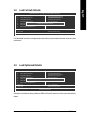
Dual Channel DDR
GA-8I915G Pro supports the Dual Channel Technology. After operating the Dual Channel Technology,
the bandwidth of Mem ory Bus will add double up to 6.4GB/s.
GA-8I915G Pro includes 4 DIMM sockets, and each Channel has two DIM M sockets as following:
Channel A : DDR 1, DDR 2
Channel B : DDR 3, DDR 4
If you want to operate the Dual Channel Technology, please note the following explanations due
to the limitation of Intel chipset specifications.
1. One/three DDR mem ory module is installed: The Dual Channel Technology can't operate
when only one DDR mem ory module is installed.
2. Two DDR mem ory modules are installed (the sam e m emory size and type): The Dual
Channel Technology will operate when two m em ory m odules are inserted individually into
Channel A and B. If you install two mem ory modules in the same channel, the Dual Channel
Technology will not operate.
3. Four DDR memory modules are installed: If you install four mem ory modules at the same
time, the Dual Channel Technology will operate only when those modules have the same
memory size and type.
We'll strongly recom mend our user to slot two DDR memory m odules into the DIMMs with the same
color in order for Dual Channel Technology to work.
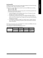
The following table is for Dual Channel Technology combination:
l Dual Channel Technology (DS: Double Side, SS: Single Side)
2 memory modules
4 memory modules
DDR 1 DDR 2 DDR 3 DDR 4
DS/SS X DS/SS X
X DS/SS X DS/SS
DS/SS DS/SS DS/SS DS/SS

GA-8I915G Pro Motherboard - 16 -
English
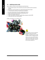
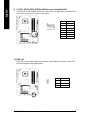
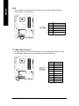
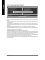
1-5 Install expansion cards
You can install your expansion card by following the steps outlined below:
1. Read the related expansion card's instruction document before install the expansion card into the
computer.
2. Remove your computer's chassis cover, screws and slot bracket from the computer.
3. Press the expansion card firmly into expansion slot in motherboard.
4. Be sure the metal contacts on the card are indeed seated in the slot.
5. Replace the screw to secure the slot bracket of the expansion card.
6. Replace your computer's chassis cover.
7. Power on the computer, if necessary, setup BIOS utility of expansion card from BIOS.
8. Install related driver from the operating system.
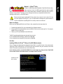
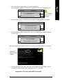
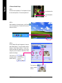
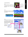
Installing a PCI Express x 16 expansion card:
Please carefully pull out the small white-
drawable bar at the end of the PCI
Express x 16 slot when you try to install/
Uninstall the VGA card. Please align the
VGA card to the onboard PCI Express x
16 slot and press firm ly down on the slot
.M ake sure your VGA card is locked by
the small white-drawable bar.

Hardware Installation- 17 -
English
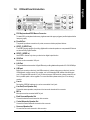
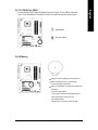
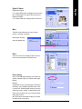
1-6 I/O Back Panel Introduction
PS/2 Keyboard and PS/2 Mouse Connector
To install a PS/2 port keyboard and mouse, plug the mouse to the upper port (green) and the keyboard to the
lower port (purple).
Parallel Port
The parallel port allows connection of a printer, scanner and other peripheral devices.
SPDIF_O (SPDIF Out)
The SPDIF output is capable of providing digital audio to external speakers or compressed AC3 data to
an external Dolby Digital Decoder.
SPDIF_I (SPDIF In)
Use SPDIF In feature only when your device has digital output function.
VGA Port
Monitor can be connected to VGA port.
LAN Port
The provided Internet connection is Gigabit Ethernet, providing data transfer speeds of 10/100/1000Mbps.
USB port
Before you connect your device(s) into USB connector(s), please make sure your device(s) such as
USB keyboard, mouse, scanner, zip, speaker...etc. have a standard USB interface. Also make sure
your OS supports USB controller. If your OS does not support USB controller, please contact OS ven
dor for possible patch or driver upgrade. For more information please contact your OS or device(s)
vendors.
Line In
Devices like CD-ROM, walkman etc. can be connected to Line In jack.
Line Out (Front Speaker Out)
Connect the stereo speakers, earphone or front surround channels to this connector.
MIC In
Microphone can be connected to MIC In jack.
Back Surround Speaker Out
Connect the back surround channels to this connector.
Center/Subwoofer Speaker Out
Connect the Center/Subwoofer channels to this connector.
Surround Speaker Out
Connect the surround channels to this connector.

GA-8I915G Pro Motherboard - 18 -
English
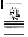
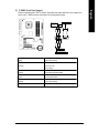
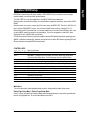
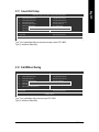
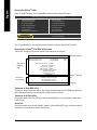
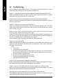
1-7 Connectors Introduction
1) ATX_12V
2) ATX (Power Connector)
3) CPU_FAN
4) SYS_FAN
5) PWR_FAN
6) NB_FAN
7) FDD
8) IDE
9) S_ATA1/S_ATA2/S_ATA3/S_ATA4
10) PWR_LED
11) F_PANEL
12) AZALIA_FP
13) CD_IN
14) F_USB1 / F_USB2
15) F1_1394 / F2_1394
16) IR
17) COMA
18) CLR_CMOS
19) BAT
2
1
13
4
18
8
3
11
12
151617
10
14
7
5
9
19
You can use audio software to configure 2-/4-/5.1-/7.1-channel audio functioning.
6

Hardware Installation- 19 -
English
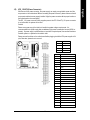
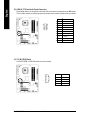
Pin No. Definition
1 GND
2 GND
3 +12V
4 +12V
3
1
4
2
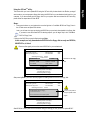
1/2) ATX_12V/ATX (Power Connector)
With the use of the power connector, the power supply can supply enough stable power to all the
components on the motherboard. Before connecting the power connector, please make sure that all
components and devices are properly installed. Align the power connector with its proper location on
the motherboard and connect tightly.
The ATX_12V power connector mainly supplies power to the CPU. If the ATX_12V power connector
is not connected, the system will not start.
Caution!
Please use a power supply that is able to handle the system voltage requirements. It is
recommended that a power supply that can withstand high power consumption be used (300W or
greater). If a power supply is used that does not provide the required power, the result can lead to an
unstable system or a system that is unable to start.
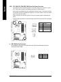
Please remove the sticker on the motherboard before plugging in while the ATX power supplier is 24
pins; Otherwise, please do not remove it.
Pin No. Definition
1 3.3V
2 3.3V
3 GND
4 VCC
5 GND
6 VCC
7 GND
8 Power Good
9 5V SB(stand by +5V)
10 +12V
11 +12V
12 3.3V(Only for 24pins ATX)
13 3.3V
14 -12V
15 GND
16 PS_ON(soft On/Off)
17 GND
18 GND
19 GND
20 -5V
21 VCC
22 VCC
23 VCC
24 GND
2 4
1 3
1 2
1

GA-8I915G Pro Motherboard - 20 -
English
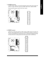
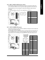
3/4/5) CPU_FAN / SYS_FAN / PWR_FAN (Cooler Fan Power Connector)
The cooler fan power connector supplies a +12V power voltage via a 3-pin/4-pin (only for
CPU_FAN) power connector and possesses a ful-proof connection design.
Most coolers are designed with color-coded power connector wires. A red power connector
wire indicates a positive connection and requires a +12V power voltage. The black connector
wire is the ground wire (GND).
Please remember to connect the power to the cooler to prevent system overheating and
failure.
Caution! Please remember to connect the power to the CPU fan to prevent CPU overheating
and failure.
1
1
CPU_FAN
SYS_FAN
PWR_FAN
1
Pin No. Definition
1 GND
2 +12V
3 Sense
4 Speed Control
(Only for CPU_FAN)
6) NB_FAN (Chip Fan Connector)
If you installed wrong direction, the chip fan will not work. Sometimes will damage the chip fan.
(Usually black cable is GND)
Pin No. Definition
1 +12V
2 GND
1
Page is loading ...
Page is loading ...
Page is loading ...
Page is loading ...
Page is loading ...
Page is loading ...
Page is loading ...
Page is loading ...
Page is loading ...
Page is loading ...
Page is loading ...
Page is loading ...
Page is loading ...
Page is loading ...
Page is loading ...
Page is loading ...
Page is loading ...
Page is loading ...
Page is loading ...
Page is loading ...
Page is loading ...
Page is loading ...
Page is loading ...
Page is loading ...
Page is loading ...
Page is loading ...
Page is loading ...
Page is loading ...
Page is loading ...
Page is loading ...
Page is loading ...
Page is loading ...
Page is loading ...
Page is loading ...
Page is loading ...
Page is loading ...
Page is loading ...
Page is loading ...
Page is loading ...
Page is loading ...
Page is loading ...
Page is loading ...
Page is loading ...
Page is loading ...
Page is loading ...
Page is loading ...
Page is loading ...
Page is loading ...
Page is loading ...
Page is loading ...
Page is loading ...
Page is loading ...
Page is loading ...
Page is loading ...
Page is loading ...
Page is loading ...
Page is loading ...
Page is loading ...
Page is loading ...
Page is loading ...
-
 1
1
-
 2
2
-
 3
3
-
 4
4
-
 5
5
-
 6
6
-
 7
7
-
 8
8
-
 9
9
-
 10
10
-
 11
11
-
 12
12
-
 13
13
-
 14
14
-
 15
15
-
 16
16
-
 17
17
-
 18
18
-
 19
19
-
 20
20
-
 21
21
-
 22
22
-
 23
23
-
 24
24
-
 25
25
-
 26
26
-
 27
27
-
 28
28
-
 29
29
-
 30
30
-
 31
31
-
 32
32
-
 33
33
-
 34
34
-
 35
35
-
 36
36
-
 37
37
-
 38
38
-
 39
39
-
 40
40
-
 41
41
-
 42
42
-
 43
43
-
 44
44
-
 45
45
-
 46
46
-
 47
47
-
 48
48
-
 49
49
-
 50
50
-
 51
51
-
 52
52
-
 53
53
-
 54
54
-
 55
55
-
 56
56
-
 57
57
-
 58
58
-
 59
59
-
 60
60
-
 61
61
-
 62
62
-
 63
63
-
 64
64
-
 65
65
-
 66
66
-
 67
67
-
 68
68
-
 69
69
-
 70
70
-
 71
71
-
 72
72
-
 73
73
-
 74
74
-
 75
75
-
 76
76
-
 77
77
-
 78
78
-
 79
79
-
 80
80


Gigabyte GA-8I915G Duo User manual
- Category
- Motherboards
- Type
- User manual
- This manual is also suitable for
Ask a question and I''ll find the answer in the document
Finding information in a document is now easier with AI
Related papers
-
Gigabyte GA-8I915GM-G Owner's manual
-
Gigabyte GA-8I915GL-MFK User manual
-
-
Gigabyte GA-8I915GL-MF Owner's manual
-
Gigabyte GA-8I915G Duo User manual
-
Gigabyte GA-8I945GMH-RH User manual
-
Gigabyte GA-8I915G-M User manual
-
Gigabyte GA-8I915G-MFD User manual
-
Gigabyte GA-8I915G Pro Owner's manual
-
Gigabyte GA-8I915MD-GV User manual
Other documents
-
Intel GA-8I915PM-FS User manual
-
-
Foxconn 915M03 Series User manual
-
ECS 915G-M (V1.0) Specification
-
Foxconn 915GL7MC User manual
-
-
Intel GA-8I945P-G User manual
-
-
DFI system board User manual
-
Ortech HVAC User manual