Page is loading ...

MADE IN ITALY
design & production
LUCIA PLUS
004277561 - Rev 003
UK
PeLLet StoveS USeR MANUAL

2 ENGLISH

3ENGLISH
ENGLISH ............................................................................................................................................................................................................ 5
WarNINGS ........................................................................................................................................................................................................ 5
SafEty .............................................................................................................................................................................................................. 5
routINE MaINtENaNcE ................................................................................................................................................................................ 7
INStaLLatIoN .................................................................................................................................................................................................. 8
PREPARATIONS FOR MAINTENANCE ..................................................................................................................................................................................................8
DEtaILS of LucIa pLuS ................................................................................................................................................................................ 10
aIr DuctING fEaturES ............................................................................................................................................................................... 11
FACTORy dEFAulT OPERATION IN AIR duCTINg MOdE .........................................................................................................................................................11
OPERATION IN AIR duCTINg wITh ThERMOSTAT OR PRObE (OPTIONAl)......................................................................................................................11
ta aDDItIoNaL tHErMoStat (optIoNaL) ............................................................................................................................................... 12
FuSE ...............................................................................................................................................................................................................................................................12
StovE poSItIoNING ..................................................................................................................................................................................... 13
NotE for corrEct opEratIoN ................................................................................................................................................................ 13
pELLEtS aND LoaDING ................................................................................................................................................................................ 14
pELLEt HoppEr - prESSurISED cLoSurE. ................................................................................................................................................ 14
rEMotE coNtroL .........................................................................................................................................................................................15
REMOTE CONTROl ICONS ....................................................................................................................................................................................................................16
INSERTINg ThE bATTERIES ...................................................................................................................................................................................................................16
AdVICE ANd PRECAuTIONS FOR ThE uSE OF ThE REMOTE CONTROl ............................................................................................................................16
toucH ScrEEN DISpLay .............................................................................................................................................................................. 17
OPENINg ThE dISPlAy ..........................................................................................................................................................................................................................17
ClOSINg ThE dISPlAy ...........................................................................................................................................................................................................................17
coNtroL BoarD ........................................................................................................................................................................................... 18
ICON kEy ......................................................................................................................................................................................................................................................18
gENERAl MENu ........................................................................................................................................................................................................................................19
gENERAl wARNINgS ..............................................................................................................................................................................................................................19
fIrSt IGNItIoN SEttINGS ............................................................................................................................................................................ 20
dATE-TIME ...................................................................................................................................................................................................................................................20
lANguAgE ..................................................................................................................................................................................................................................................20
dEgREES ......................................................................................................................................................................................................................................................20
opEratIoN aND LoGIc ................................................................................................................................................................................ 21
froNt aIr ......................................................................................................................................................................................................22
aIr DuctING 1 ............................................................................................................................................................................................... 22
aIr DuctING 2 ............................................................................................................................................................................................... 22
EaSy SEtup ...................................................................................................................................................................................................23
cHroNo .......................................................................................................................................................................................................... 24
ENAblINg/dISAblINg ThE ChRONO ..............................................................................................................................................................................................24
SEttINGS ........................................................................................................................................................................................................ 26
uPdATE .........................................................................................................................................................................................................................................................26
STANd - by ..................................................................................................................................................................................................................................................26
OPERATION wITh AddITIONAl ThERMOSTAT (OPTIONAl) .................................................................................................................................................26
AddITIONAl ThERMOSTAT ..................................................................................................................................................................................................................27
dElTA T .........................................................................................................................................................................................................................................................27
FIRST lOAd .................................................................................................................................................................................................................................................27
wI-FI ...............................................................................................................................................................................................................................................................27
RESET .............................................................................................................................................................................................................................................................28
cLEaNING aND MaINtENaNcE ................................................................................................................................................................... 29
MaINtENaNcE ............................................................................................................................................................................................... 29
PERIOdIC ClEANINg uNdER uSER'S RESPONSIbIlITy .............................................................................................................................................................29
routINE MaINtENaNcE pErforMED By quaLIfIED tEcHNIcIaNS .................................................................................................... 31
ShuT-dOwN (ENd OF SEASON) ........................................................................................................................................................................................................31
DISpLayS ........................................................................................................................................................................................................ 34
aLarMS .......................................................................................................................................................................................................... 34
GuaraNtEE tErMS ...................................................................................................................................................................................... 35
DISpoSaL........................................................................................................................................................................................................ 36
attENtIoN
SurfacES caN BEcoME vEry Hot!
aLWayS uSE protEctIvE GLovES!
During combustion, thermal energy is released that signicantly increases the heat of surfaces, doors, handles, controls, glass, exhaust
pipes, and even the front of the appliance. Avoid contact with those elements if not wearing protective clothing (protective gloves
included). Make sure children are aware of the danger and keep them away from the stove during operation.

ATTENZIONE TASSATIVO
PrImA dI mOVImENTArE lA STufA TOglIErE lE
mAIOlIchE INdIcATE PEr EVITArE dANNI.
ATENÇÃO - OBrIgATÓrIO
ANTES dE mOVImENTAr A SAlAmANdrA, rE-
TIrAr AS cErâmIcAS INdIcAdAS PArA EVITAr
dANOS.
ATTENTION - cOmPulSOrY
BEfOrE mOVINg ThE STOVE, kINdlY TAkE ThE
cErAmIcS Off IN OrdEr TO
AVOId ANY dAmAgES
TÄhElEPANu!
ENNE Ahju lIIguTAmIST EEmAldAgE SEllElT
NÄIdATud kErAAmIlISEd OSAd, ET VÄlTIdA
kAhjuSTuSI.
ATTENTION - OBlIgATOIrE
AVANT dE BOugEr lE POêlE , fAIrE ATTENTION à
lEVEr lES cérAmIquES
INdIquéES POur éVITEr dES dégâTS
OBVEZNA POZOrNOST
PrIjE POmIcANjA PEćI, uklONITE OZNAčENE
PlOčIcE kAkO BISTE IZBjEglI OšTEćENjA.
VOrSIchT - OBlIgATOrISch
BEVOr SIE dEN OfEN BEwEgEN, BITTE uNBE-
dINgT dIE BEZEIchNETE kErAmIk kAchElN
ENTfErNEN um SchÄdEN Zu VErmEIdEN
POZOr OBVEZNO
PrEd PrEmIkANjEm PEčI OdSTrANITE OZNAčENE
mAjOlIkE, dA PrEPrEčITE POškOdOVANjE.
ATENcIÓN - PErENTOrIO
ANTES dE mOVEr lA ESTufA SAcAr lAS
mAYÓlIcAS INdIcAdAS PArA EVITAr dAñOS.
AdVArSEl - OBlIgATOrISk
før du flYTTEr OVNEN, Bør du TAgE
kErAmIkflISErNE Af fOr AT uNdgå SkAdEr.
4 ENGLISH

5ENGLISH
Warnings
This instructions manual is an integral part of the product: make sure that
it always accompanies the appliance, even if transferred to another owner
or user, or if transferred to another place. If it is damaged or lost, request
another copy from the area technician. This product is intended for the use
for which it has been expressly designed. The manufacturer is exempt from
any liability, contractual and extracontractual, for injury/damage caused to
persons/animals and objects, due to installation, adjustment and mainte-
nance errors and improper use.
Installation must be performed by qualied sta, which assumes com-
plete responsibility for the denitive installation and consequent good
functioning of the product installed. One must also bear in mind all laws
and national, regional, provincial and town council Standards present
in the country in which the appliance has been installed, as well as the
instructions contained in this manual.
The Manufacturer cannot be held responsible for the failure to comply
with such precautions.
After removing the packaging, ensure that the content is intact and com-
plete. Otherwise, contact the dealer where the appliance was purchased.
All electric components that make up the product must be replaced with
original spare parts exclusively by an authorised after-sales centre, thus
guaranteeing correct functioning.
safety
THE APPLIANCE MAY BE USED BY CHILDREN 8 YEARS OF AGE OR
OLDER AND INDIVIDUALS WITH REDUCED PHYSICAL, SENSORY, OR
MENTAL CAPACITIES OR WITHOUT EXPERIENCE OR THE NECESSARY
KNOWLEDGE, PROVIDED THAT THEY ARE SUPERVISED OR HAVE
RECEIVED INSTRUCTIONS ON SAFE USE OF THE APPLIANCE AND THAT
THEY UNDERSTAND THE INHERENT DANGERS.
THE GENERATOR MUST NOT BE USED BY PERSONS INCLUDING
We thank you for having chosen our company; our product is a great heating solution developed from the
most advanced technology with top quality machining and modern design, aimed at making you enjoy the
fantastic sensation that the heat of a ame gives, in complete safety.

6 ENGLISH
CHILDREN WITH REDUCED PHYSICAL, SENSORY AND MENTAL
CAPACITIES OR WHO ARE UNSKILLED PERSONS, UNLESS THEY ARE
SUPERVISED AND TRAINED REGARDING USE OF THE APPLIANCE BY A
PERSON RESPONSIBLE FOR THEIR SAFETY.
THE CLEANING AND MAINTENANCE REQUIRED BY THE USER MUST
NOT BE PERFORMED BY CHILDREN WITHOUT SUPERVISION.
CHILDREN MUST BE CHECKED TO ENSURE THAT THEY DO NOT PLAY
WITH THE APPLIANCE.
DO NOT TOUCH THE GENERATOR WHEN YOU ARE BAREFOOT OR
WHEN PARTS OF THE BODY ARE WET OR DAMP.
THE SAFETY AND ADJUSTMENT DEVICES MUST NOT BE
MODIFIED WITHOUT THE AUTHORISATION OR INDICATIONS OF THE
MANUFACTURER.
DO NOT PULL, REMOVE, TWIST THE ELECTRICAL CABLES COMING
OUT OF THE PRODUCT EVEN IF IT IS DISCONNECTED FROM THE MAINS.
IT IS ADVISED TO POSITION THE POWER SUPPLY CABLE SO THAT IT
DOES NOT COME INTO CONTACT WITH HOT PARTS OF THE APPLIANCE.
THE POWER SUPPLY PLUG MUST BE ACCESSIBLE AFTER
INSTALLATION.
DO NOT CLOSE OR REDUCE THE DIMENSIONS OF THE AIRING VENTS
IN THE PLACE OF INSTALLATION. THE AIRING VENTS ARE ESSENTIAL
FOR CORRECT COMBUSTION.
DO NOT LEAVE THE PACKAGING ELEMENTS WITHIN REACH OF
CHILDREN OR UNASSISTED DISABLED PERSONS.
THE HEARTH DOOR MUST ALWAYS BE CLOSED DURING NORMAL
FUNCTIONING OF THE PRODUCT.
WHEN THE APPLIANCE IS FUNCTIONING AND HOT TO THE TOUCH,
ESPECIALLY ALL EXTERNAL SURFACES, ATTENTION MUST BE PAID
CHECK FOR THE PRESENCE OF ANY OBSTRUCTIONS BEFORE
SWITCHING THE APPLIANCE ON FOLLOWING A PROLONGED PERIOD
OF INACTIVITY.
THE GENERATOR HAS BEEN DESIGNED TO FUNCTION IN ANY
CLIMATIC CONDITION. IN PARTICULARLY ADVERSE CONDITIONS
STRONG WIND, FREEZING SAFETY SYSTEMS MAY INTERVENE
THAT SWITCH THE GENERATOR OFF. IF THIS OCCURS, CONTACT THE
TECHNICAL AFTERSALES SERVICE AND ALWAYS DISABLE THE SAFETY

7ENGLISH
SYSTEMS.
IN THE EVENT THE FLUE CATCHES FIRE, USE SUITABLE SYSTEMS
FOR SUFFOCATING THE FLAMES OR REQUEST HELP FROM THE FIRE
BRIGADE.
THIS APPLIANCE MUST NOT BE USED TO BURN WASTE
DO NOT USE ANY FLAMMABLE LIQUIDS FOR IGNITION
DURING THE FILLING PHASE DO NOT PUT THE BAG OF PELLETS TO
INTO CONTACT WITH THE PRODUCT
THE MAJOLICAS ARE TOP QUALITY ARTISAN PRODUCTS AND
AS SUCH CAN HAVE MICRODOTS, CRACKLES AND CHROMATIC
IMPERFECTIONS. THESE FEATURES HIGHLIGHT THEIR VALUABLE
NATURE. DUE TO THEIR DIFFERENT DILATION COEFFICIENT, THEY
PRODUCE CRACKLING, WHICH DEMONSTRATE THEIR EFFECTIVE
AUTHENTICITY. TO CLEAN THE MAJOLICAS, IT IS RECOMMENDED TO
USE A SOFT, DRY CLOTH. IF A DETERGENT OR LIQUID IS USED, THE
LATTER COULD PENETRATE INSIDE THE CRACKLES, HIGHLIGHTING
THEM.
SINCE THE PRODUCT CAN TURN ON AUTOMATICALLY THANKS TO
THE TIMER, OR REMOTELY USING THE DEDICATED APPLICATIONS, IT IS
STRICTLY FORBIDDEN TO LEAVE ANY COMBUSTIBLE OBJECT WITHIN
THE SAFETY DISTANCES INDICATED ON THE TECHNICAL DATA PLATE.
INTERNAL COMBUSTION CHAMBER PARTS CAN BE SUBJECT TO
EXTETICAL WARN, IT DOESN'T AFFECT THE FUNCTIONALITY
routine Maintenance
Based on Decree 22 January 2008 n°37 art.2, routine maintenance means
interventions aimed at reducing degradation due to normal use, as well
as dealing with accidental events entailing the need of rst interventions,
which however do not modify the structure of the system upon which one
is intervening or its intended use according to the requirements laid down
by the technical standards in force and by the manufacturer's use and main-
tenance manual.

8 ENGLISH
INSTALLING INSERTS
When installing inserts, access must be prevented to the internal parts of the appliance and it must not be possible to access live parts during
extraction operations.
Any wiring, for example the power cable or room probe, must be positioned so as not to be damaged during movement of the insert and must
not come into contact with hot parts. If a cavity made of combustible material is installed, we recommend taking all the safety precautions
indicated by the installation standards.
VENTILATION AND AERATION OF INSTALLATION ROOMS
In case of non-airtight heater and/or installation, the ventilation must respect the minimum area indicated below (considering the highest value
among those provided):
Appliance categories Reference standard
Percentage of the
net opening section with respect to the
appliance fumes outlet section
Minimum net opening value of the
ventilation duct
Pellet stoves UNI EN 14785 - 80 cm²
Boilers UNI EN 303-5 50% 100 cm²
INSTALLATION
GENERAL
The ue gas exhaust and hydraulic connections must be carried out by qualied personnel who must issue installation conformity
documentation compliant with national standards.
The installer must provide the owner or person acting for him, according to the legislation in force, with the declaration of conformity,
supplied with:
1) the use and maintenance manual of the appliance and of the system components (such as for example, the smoke ducts, chimney, etc.);
2) photocopy or photograph of the chimney plaque;
3) system booklet (where applicable).
The installer must ask to be issued with a receipt stating that the documentation has been provided, and must keep it with a copy of the technical
documentation relating to the installation.
For installation in a condominium, prior approval from the condominium's administrator must be requested.
Where required, check the exhaust gas emissions after installation. Should a sampling point be installed, it must be airtight.
COMPATIBILITY
Do not install in rooms with a re hazard. It is also forbidden to install it in living areas with the following characteristics:
1. where there are liquid fuel appliances with continuous or discontinuous operation that draw the combustion air into the room in which they
are installed.
2. where there are type B gas appliances intended for heating, with or without domestic hot water production and in adjacent and communicating
rooms.
3. where the depression measured in situ between the external and internal environment is greater than 4 Pa.
N.B.: Watertight appliances can also be installed in the cases indicated in points 1, 2 and 3 of this paragraph.
INSTALLATIONS IN BATHROOMS, BEDROOMS AND STUDIO FLATS
Installation in bathrooms, bedrooms and studio ats is only allowed for sealed or closed hearth appliances with ducted combustion air taken
from the outside.
oor protection
POSITIONING AND SAFETY DISTANCES
The support surfaces and/or points must have a suitable capacity to bear the overall weight
of the appliance, accessories and coverings. If the oor is made of a combustible material,
we recommend using a non-combustible material to protect the front part from any burnt
material which might fall during routine cleaning operations. The generator must be level
to function properly. The side walls, the rear walls and the oor support surface should be
made of non-combustible material.
One must also bear in mind all laws and national,
regional, provincial and town council regulations in force
in the country in which the appliance has been installed,
as well as the instructions contained in this manual.
Air inlet
Under any condition, including in the presence of extractor hoods and/or of controlled forced ventilation systems, the pressure dierence
between the generator installation rooms and the outside must always be equal to or less than 4 Pa.
MINIMUM DISTANCES PELLET STOVES
Installation next to ammable or heat-sensitive materials is permitted only if the special
safety distances specied on the label at the beginning of the manual (pag.2) are
observed. If the materials are not ammable, you must keep a side and rear distance of at
least 100 mm (without the inserts). For products equipped with rear spacers, wall-mounting
installation is permitted exclusively for the rear side.
PREPARATIONS FOR MAINTENANCE
To carry out extraordinary maintenance operations on the product, it may be necessary to move it away from the adjacent walls. This must be
done by a technician authorised to disconnect the combustion product evacuation ducts and then reconnect them. For heaters connected to the
hydraulic system, the connection between the system itself and the product must be made in such a way that, when an authorised technician is
about to carry out extraordinary maintenance operations, it is possible to move the heater at least 1 metre away from the adjacent walls.

3 - 5%
Max 3 mt
9ENGLISH
EXAMPLES OF CORRECT CONNECTION TO THE CHIMNEY
In the presence of type B gas appliances with intermittent operation not intended for heating, they must have their own aeration and/or
ventilation opening.
The air inlets must meet the following requirements:
they must be protected with grids, metal mesh, etc., but without reducing the net useful section;
they must be made so as to make the maintenance operations possible;
positioned so that they cannot be obstructed;
The clean and non-contaminated air ow can also be obtained from a room adjacent to that of installation (indirect aeration and
ventilation), as long as the ow takes place freely through permanent openings communicating with the outside.
The adjacent room cannot be used as a garage, or to store combustible material or for any other activity with a re hazard, bathroom,
bedroom or common room of the building.
FLUE GAS EXHAUST
The heat generator works in depression and is equipped with an outlet fan for ue gas extraction. There must be a single exhaust system for
the generator. Using a ue that is shared with other devices is not allowed.
The components of the ue gas exhaust system must be chosen in relation to the type of appliance to be installed in compliance with:
UNI/ TS 11278 in the event of metal chimneys, with particular attention to that stated in the specication;
UNI EN 13063-1 and UNI EN 13063-2, UNI EN 1457, UNI EN 1806 in the event of non-metallic chimneys.
The length of the horizontal section must be minimal and, in any case, no longer than 3 metres, with a minimum upward slope of 3%
There must not be more than 4 direction changes including the one due to the use of the "T" element.
A “T” tting with a condensation collection cap must be provided at the base of the vertical section.
If the exhaust is not inserted in an existing ue, a vertical section with a windproof end piece is required (UNI 10683).
The vertical duct can be inside or outside the building. If the smoke duct is inserted in an existing ue, it must be certied for solid fuel.
If the smoke duct is outside the building, it must always be insulated.
The smoke ducts must have at least one airtight inlet for ue gas sampling.
All the sections of the ue gas duct must be accessible to inspection.
Inspection openings must be provided for cleaning.
If the generator has a fume temperature lower than 160°C+ ambient temperature caused by the high yield (contact technicians) it
MUST be resistant to humidity.
A ue system that does not respect the previous points or, in general, that does not comply with the regulations, may cause condensation
phenomena inside it.
CHIMNEY CAP
The chimney caps must meet the following requirements:
they must have a useful outlet section no less than double that of the chimney/ducted system on which it is installed;
they must be adapted in order to prevent the penetration of rain and snow in the chimney/ducted system;
they must be built so that, in the event of winds coming from all directions and from any angle, the expulsion of combustion products
is in any case ensured;
Protection from rain
and wind
Condensation-proof
"T" tting with
inspection plug
Insulated ue
Insulated "T"
tting with
inspection plug
Protection from rain and wind
"T" tting with
inspection
plug
CONNECTION TO THE MAINS ELECTRIC SUPPLY
The generator is supplied with an electric power cable to be plugged into a 230V 50 Hz socket, possibly with a circuit breaker switch. The
socket must be easily accessible.
The electrical system must be compliant with standards. The eciency of the earthing circuit must be checked. Unsuitable earthing of the
system can cause malfunctioning for which the manufacturer will not be held liable.
Power supply variations beyond 10% can cause faulty operation of the product.

A
C
D
F
G
K
E
B
J
H
I
L
10 ENGLISH
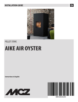
DEtAILs oF LUCIA pLUs
A
Ambient air outlet
F
Combustion air inlet
J
Air Ducting Z2 inlets
B
Access to combustion chamber
and ash drawer
G
Air ducting Z2 outlet Air ducting Z1 inlets
C
Touch screen display
H
Air ducting Z1 outlet TA additional thermostat input
D
Pellet hopper pressurised closure
I
Ambient probe
K
On/O
Fuse
E
Fumes outlet
230 V power supply
L
Serial input

11ENGLISH
WITH PROBE NTC 10K
Remove the jumper on 1 and connect the NTC probe in the room that needs to be temperature-controlled through air ducting 1.
3 control modes:
air ducting features
The stove has 2 independent outlets for air ducting.
Air ducting 1 - 2 are enabled by factory default.
Features:
diameter of air ducting outlet: 2x80 mm
maximum recommended air ducting length 8 m
temperature controlled air ducting
Speed regulation can be set in 3 modes: OFF, AUTO, COMFORT
independent air ducting with option for enabling/disabling (ONOFF)
factory default operation in air ducting mode
Air ducting 1 and 2 are always in request by factory default (jumpers on 1 and 2 present), and follow the stove settings.
- No settings necessary.
operation in air ducting with thermostat or probe (optional)
The stove is tted with two independent motors for air ducting. The connection of an external thermostat or temperature probe (NTC 10K)
in inputs 1 and 2, located in the rear part of the stove, makes it possible to control the air ducting motor independently of the stove.
Suce it to connect the thermostat/temperature probe and set the desired temperature.
For information on air ducting settings see chapter:" Menu - Air ducting"
WITH AMBIENT THERMOSTAT OPTIONAL
Remove the jumper on 1 and connect the ambient thermostat in the room that needs to be temperature-controlled through air ducting 1.
3 control modes:
OPERATION IN AIR DUCTING WITH AMBIENT THERMOSTAT OPTIONAL
SET congured to OFF
(the temperature setting is not visible)
The air ducting motor will remain o unless the fumes temperature exceeds the
normal operating temperatures
SET congured to AUTO
(the temperature setting is not visible)
Once the specic activation threshold has been reached and exceeded, at temperature
to be satised (CLOSED CONTACT) the air ducting motor will follow the stove settings.
When the temperature set on the thermostat is reached (OPEN CONTACT), the air
ducting motor will switch OFF and switch on again when there is a new request.
SET congured to COMFORT
(the temperature setting is not visible)
Once the specic activation threshold has been reached and exceeded, at temperature
to be satised (CLOSED CONTACT) the air ducting motor will follow the stove settings
but at a lower speed than in SET AUTO for increased acoustic/ambient comfort.
When the temperature set on the thermostat is reached (OPEN CONTACT), the
ducting motor will switch o and switch on again when there is a new request.
SAMe OPerAting SettingS FOr Air ducting 2 MOtOr

12 ENGLISH
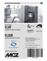
ta additional thermostat (optional)
The appliance is able to control the room temperature through an additional thermostat (optional).
After ignition (by pressing key 1 or in chrono mode), the stove will work to reach the set value on the thermostat, displaying WORK (closed
contact) on the screen. The on-board ambient probe will automatically be ignored.
installation must be performed by qualified staff and/or the manufacturer's service technicians
TO INSTALL AND ACTIVATE:
A mechanical or digital thermostat is required.
Remove the plug from the socket.
Using the image to the side as a guide, connect the two thermostat wires (clean contact - no 230 V!)
to the respective terminals at the back of the machine, one red and the other black.
Connect the power to the stove again.
The stove is now correctly congured.
It will work by checking the external additional thermostat based on the TA function.
OPERATION IN AIR DUCTING WITH NTC PROBE 10K OPTIONAL
SET congured to OFF
Set the desired temperature ( from 7 to 37 °C)
The air ducting motor will remain o unless the fumes temperature exceeds the
normal operating temperatures
SET congured to AUTO
Set the desired temperature ( from 7 to 37 °C)
Once the specic activation threshold has been reached and exceeded, at temperature
to be satised the air ducting motor will follow the stove settings.
When the temperature set in TEMPERATURE is reached, the air ducting motor will
switch OFF and switch on again when there is a new request.
SET congured to COMFORT
Set the desired temperature ( from 7 to 37 °C)
Once the specic activation threshold has been reached and exceeded, at temperature
to be satised the air ducting motor will follow the stove settings but at a lower speed
than in SET AUTO for increased acoustic/ambient comfort.
When the temperature set in TEMPERATURE is reached, the air ducting motor will
switch o and switch on again when there is a new request.
SAMe OPerAting SettingS FOr Air ducting 2 MOtOr
fuse
If there is no power supply to the stove, check the
state of the fuse located in the box between the
stove switch and the power cord connection.
J
for correct operation set
the ambient SET THERMOSTAT to LOWTA

13ENGLISH
note for correct operation
Pellet hopper lid
Fire door
The following indications must be respected for correct pellet
stove operation:
Both during the functioning and when the stove is not in use,
all the machine doors (pellet hopper, re door, ash drawer) must
always remain closed. The machine doors can only be opened
for the time required to load the pellet and for maintenance.
"CLOSE HOPPER STOVE DOOR"
This indication means that you have 60 seconds to close the
hatch/door and the pellet lid.
Once 60 seconds have passed, during ignition the stove will
go into "DEPR ALARM" mode, while during normal operation
the stove will go into "COOLING STAND BY" mode before
automatically resuming operation once the conditions are
satised (cold stove, etc.).
stove positioning
To ensure the stove works correctly, it should always be positioned so that it is perfectly level, using a spirit level.

14 ENGLISH
PELLETS AND LOADING
Pellets are made by subjecting wood shavings i.e. the rejects of pure unpainted wood from sawmills, carpentry products and products from
other activities connected to wood working and transformation, to very high pressures.
This type of fuel is fully ecological as no glues are used for its compaction. In fact, pellet compactness is guaranteed over time by a natural
substance found in wood: lignite.
In addition to being an ecological fuel, making best use of wood residue, pellets also have a series of technical advantages.
While wood has a caloric value of 4.4 kWh/kg (with 15% moisture, therefore after approximately 18 months of curing), that of pellets is 5
kWh/kg.
Pellet density is about 650 kg/m
3
and water content is equal to 8% of its weight. For this reason pellets do not need to be cured to obtain a
sucient heat yield.
THE USE OF POOR QUALITY PELLETS OR ANY OTHER MATERIAL WILL COMPROMISE STOVE FUNCTIONS, VOIDING
THE WARRANTY AND RELEASING THE MANUFACTURER OF LIABILITY.
PELLET HOPPER PRESSURISED CLOSURE.
During stove operation, the pellet hopper lid must always be closed.
Keep clean
Do not place the bag Directly on the stove to loaD the tank.
always use a scoop to loaD the tank. Do not rub or place weights on the tank seal. keep the tank cover
seal supporting surface clean at all times. check the conDitions of the seal frequently. if DamageD,
contact your local authoriseD technician.
The pellets used must comply with the characteristics described by the
following standards:
EN PLUS class A1, ISO 17225-2 class A1
and
UNI EN 3035 with the following characteristics: water content ≤ 12%,
ash content ≤ 0.5% and lower caloric value >17 MJ/kg (in the case of
boilers).
The manufacturer always recommended using pellets with a diameter
of 6 mm with its products.
PELLET STORAGE
In order to ensure problem-free combustion pellets must be stored in
a dry place.
Open the tank lid and load the pellets using a scoop.

2
3
4
5
1
6
7
8
9
10
12
11
15ENGLISH
Remote contRol
The remote control can be used to adjust the main stove functions.
1
Transmitter
7
Select air mode
2
Display
8
Lock keyboard
3
On/o stove (hold for 3 seconds)
9
Degrees Celsius / Fahrenheit
4
Set power
10
Press the button once to enable or disable the chrono
5
Set switch-o delay: The button allows to set the switch-
o delay.
For example, if you set it to one hour, the stove will
automatically switch o after the set time *
11
Reset*
6
Set room temperature
12
Battery compartment
* not available in this model

16 ENGLISH
InseRtIng the batteRIes
Remove the battery compartment cover by sliding it down. Insert 2 AAA
batteries.
Insert the batteries respecting the correct polarity (+) and (-).
Close the cover of the battery compartment.
Respect the environment!
Used batteries contain metals that are harmful to the environment, and therefore must be disposed of separately in
special containers.
If the Remote contRol Is swItched off due to no batteRy
Installed, the stove can be contRolled fRom the
command panel located on the uppeR paRt of the stove.
when changIng the batteRIes, make suRe you follow the
symbols pRInted InsIde the Remote contRol.
Remote contRol Icons
advIce and pRecautIons foR the use of the
Remote contRol
Remove the batteries if it is not used for a long time.
When being used, direct it towards the stove's signal receiver.
Handle the remote control with care. When it is not being used, place it
on the special base supplied.
The remote control must not be left in a place where it is exposed to
direct sunlight or near a source of heat.
The quality of the signal may be aected by other IR sources.
Air mode selected:
Flashing COMFORT
On AUTO
Enable chrono
Light on = activated
Light o = deactivated
Set switch-o delay
Indicates the transmission of the radio
signal
On = during all radio communication
O = radio communication absent
Battery low Keys locked
Set power level.
The power level is displayed, instead of the set room temperature, for 3 seconds when one of the set
power buttons is pressed (4).
J
THE REMOTE CONTROL IS FITTED WITH AN LCD BACKLIT DISPLAY. THE BACKLIGHTING LASTS 20 SECONDS FROM THE
LAST PRESS OF A BUTTON. AFTER A CERTAIN TIME, TO SAVE BATTERY POWER, THE DISPLAY TURNS OFF ENERGY SAVING
MODE.
THE CONTROL FUNCTIONS ARE REACTIVATED WHEN THE REMOTE IS REMOVED FROM ITS UNIT OR BY A LONG PRESS OF
THE BUTTON.

L
A
B
17ENGLISH
TOUCH SCREEN DISPLAY
The stove is equipped with a modern touch screen display with Wi-Fi technology that allows for the individual functions of the unit to be
adjusted by the user in an easy and intuitive manner.
Touch the buttons (icons) on the display to activate the actions. The touch screen display reacts with the touch of your ngers.
CAUTION!
Do not use screen protectors: the display might not work properly
Do not place the touch screen display in direct or indirect contact with water. The touch screen display may not work properly in the
presence of humidity or if it is exposed to water.
To avoid damaging the touch screen display, do not touch it with sharp objects and do not press it too hard with your ngers.
During opening and closure, press only on the outer frame of the Display.
TOUCH SENSITIVE PARTS
FREQUENCY BANDS MAXIMUM POWER TRANSMITTED
Wi-Fi 20.0 DBM
BLUETOOTH Class-3
OPENING THE DISPLAY
Unlock the display by pressing on the edges of the display (A).
Lift the display until you hear a “click”.
CLOSING THE DISPLAY
Unlock the display by moving the lever on the back of the display (B).
Lower the display as shown in gure (A) until it is completely closed.

2
3
1
4
5
6
18 ENGLISH
CONTROL BOARD
VIEWING OF VARIOUS
TEXT MESSAGES
1
On/o stove.
2
Increase operating power / scroll through the menus.
3
Decrease operating power / scroll through the menus.
4
Increase operating set thermostat / scroll through the menus.
5
Decrease operating set thermostat / scroll through the menus.
6
To access the menu / conrm key.
ICON KEY
!
0
WI-FI BT STBY
OK
ON
Indicates the presence of an alarm.
O: indicates there are no alarms
On: indicates the presence of an alarm
!
0
WI-FI BT STBY
OK
ON
Delayed switch-o icon.
O: deactivated.
On: activated.
!
0
WI-FI BT STBY
OK
ON
Indicates the reception of the IR signal
On = IR command received
O = IR communication absent
!
0
WI-FI BT STBY
OK
ON
Indicates the weekly programming status
O: deactivated.
On: activated.
The number indicates the current reference time frame.
!
0
WI-FI BT STBY
OK
ON
Indicates contact of the external additional thermostat
Closed contact: the contact of the external additional
thermostat is closed.
Open contact: the contact of the external additional
thermostat is open.
!
0
WI-FI BT STBY
OK
ON
Wi-Fi icon
O: deactivated.
On: activated and connected to the home network.
Flashing: activated but not connected to the home network.
!
0
WI-FI BT STBY
OK
ON
Indicates the stove power.
Flame on: stable power.
Flame ashing: the power is changing.
The dashes indicate the actual power of the machine.
!
0
WI-FI BT STBY
OK
ON
STANDBY function icon
O: deactivated.
On: activated.
!
0
WI-FI BT STBY
OK
ON
It indicates the operation of the tangential fan.
O = ventilation not active.
On = ventilation active.
Flashing: ventilation at reduced speed for compensation.
!
0
WI-FI BT STBY
OK
ON
Not in use

1
2
3
4
5
6
6
2
3
1
5
4
19ENGLISH
GENERAL MENU
J
MAKE SURE THAT THE BOTTOM OF THE BURN POT IS FREE FROM
RESIDUE AND DEPOSITS. THE HOLES AT THE BOTTOM MUST BE
COMPLETELY FREE TO GUARANTEE PROPER COMBUSTION. THE "EASY
SETUP" FUNCTION CAN BE USED TO ADAPT COMBUSTION BASED ON
THE DESCRIBED NEEDS.
BURN POT BASE
FRONT AIR SET
AIR DUCTING 1
SET
TEMPERATURE*
AIR DUCTING 2
SET
TEMPERATURE*
EASY SETUP SET
CHRONO ENABLING
PRG1
PRG2
SETTINGS
DATETIME PRG3
LANGUAGE PRG4
DISPLAY
STANDBY
DELTAT
FIRST LOAD
DEGREES
WIFI
*IF A TEMPERATURE PROBE IS CONNECTED
**TECHNICIANS ONLY
**STOVE STATUS
RESET
**MENU
TECHNICIAN
Go back - exit
Scroll parameters: next (3); previous (2)
Modify data settings: increase (4); decrease (5)
Conrm - access menu
GENERAL WARNINGS
Advice to follow for the rst start-ups of the product:
During the rst hours of operation, there may be some smoke or
odours, but they are due to the normal “thermal break-in” process.
During this process, the duration of which changes depending on
the product, it is recommended to:
Ventilate the room well
If present, remove any majolica parts from the top of the
product
Activate the product at the maximum power and temperature
Avoid remaining in the room for a long time
Do not touch the surfaces of the product
Notes:
The process is completed after a few heating/cooling cycles.
Do not use for the combustion of elements or substances other than
those indicated in the manual.
Before turning on the product, it is necessary to perform the
following checks:
If it is intended to be connected to a hydraulic system, it must
be complete and fully functional and in compliance with the
instructions given in the product manual and with the relevant
regulations in force.
The pellet hopper must be completed loaded
The combustion chamber and the burn pot must be clean
Make sure that the re holder, the ash pan and the pellet
hopper close hermetically (if present in the hermetic version); they
must be closed and there must be no foreign bodies in the sealing
elements and gaskets.
Check that the power cord is properly connected
The bipolar switch (if present) must be set to position “1”.

20 ENGLISH
FIRST IGNITION SETTINGS
Once the power cord at the back of the stove has been connected, move the switch, also located on the back, to (I).
The switch at the back of the stove powers the stove board.
The stove remains o and a rst screen appears on the panel reading OFF .
DATETIME
This menu allows the date and time to be set.
CONTROLS PROCEDURE
Press key 6.
Press key 3 until SETTINGS appears and conrm by pressing key 6.
Conrm DATETIME by pressing key 6 and using keys 4 and 5 to set the day.
Continue by pressing key 6.
Use keys 4 or 5 to set and key 6 to advance, to regulate the day, hour, minutes, date, month, year.
Press key 6 to conrm and key 1 to scroll back through the menus until the initial page.
LANGUAGE
This menu allows the preferred language to be selected.
The available languages are: Italian - English - German - French - Spanish - Portuguese - Danish - Estonian - Croatian - Slovenian - Dutch -
Polish.
CONTROLS PROCEDURE
Press key 6.
Press key 3 until SETTINGS appears and conrm by pressing key 6.
Press key 3 until LANGUAGE appears and conrm by pressing key 6.
Select the language using keys 4 or 5.
Press key 6 to conrm and key 1 to scroll back through the menus until the initial page.
DEGREES
This menu allows you to set the unit of measure for the temperature. The predened value is °C.
CONTROLS PROCEDURE
Press key 6.
Press key 3 until SETTINGS appears and conrm by pressing key 6.
Press key 3 until DEGREES appears and conrm by pressing key 6.
Use keys 4 -5 to select Celsius or Fahrenheit.
Press key 6 to conrm and key 1 to scroll back through the menus until the initial page.
J
NO IGNITION
THE APPLIANCE MAY FAIL TO LIGHT BECAUSE THE AUGER IS EMPTY AND NOT ALWAYS ABLE TO LOAD THE BURN
POT FAST ENOUGH WITH THE PELLETS NEEDED FOR NORMAL IGNITION. IF THE PROBLEM OCCURS AFTER ONLY A
FEW MONTHS OF OPERATION, CHECK THAT THE ROUTINE CLEANING DESCRIBED IN THE STOVE HANDBOOK HAS
BEEN CARRIED OUT CORRECTLY
/