Page is loading ...

APP4V1043TP
7.5/10 V4 PUMP MANUAL
REV030921

1
7.5/10 V4 PUMP MANUAL REV030921
Contents
Safety Information
2-4
Breathable Air
2
Area
3
Piping
3
Installation
4-5
Operation
6
Maintenance
7-8
Pump Explosion/Part List
9-17
Troubleshooting
18
Warranty Statement
19-20

2
7.5/10 V4 PUMP MANUAL REV030921
SAFTEY INFORMATION
This manual contains very important information to know and understand. This is to provide for SAFTEY and to PREVENT
EQUIPMENT PROBLEMS. To help understand this information, observe the following:
DANGER: Danger indicates and imminently hazardous situation which, if not avoided, will result in death or
serious injury.
WARNING: Warning indicates a potentially hazardous situation which if not avoided, could result in death or serious
injury.
CAUTION: Caution indicates a potentially hazardous situation which, if not avoided, may result in minor or
moderate injury.
NOTICE: Notice indicates important information, that if not followed, may cause damage to equipment.
CALIFORNIA PROPOSITION 65
WARNING: This product or its power cord may contain chemicals known to the state of California to cause cancer
and birth defects or other reproductive harm. Wash hands after handling.
1. Allow only trained, authorized persons who have read and understood these operating instructions to use this
equipment. Failure to follow the instructions, procedures and safety precautions in this manual can result in
accidents and injuries.
2. NEVER start or operate the pump under unsafe conditions. Tag the compressor, disconnect, and
lock out all power to it to prevent accidental start-up until the condition is corrected.
3. Install, use, and operate the pump only in full compliance with all pertinent OSHA regulations and
all applicable Federal, State & Local codes, standards, and regulations.
4. Keep a first aid kit in a convenient place. Seek medical assistance promptly in case of injury. Avoid
infection by caring for any small cuts and burns promptly.
BREATHABLE AIR
1. NEVER use air from this pump for breathable air except in full compliance with OSHA Standards 29 CFR
1910 and any other Federal, State or Local codes or regulations.
2. DO NOT use airline anti-icer systems in air lines supplying respirators or other equipment used to produce
breathable air. DO NOT discharge air from these systems in unventilated or other confined areas.
3. DO NOT use airline anti-icer systems in airlines supplying respirators or other equipment used to produce
breathable air. DO NOT discharge air from these systems in unventilated or confined areas.
DANGER: Death or serious injury can result from inhaling compressed air
without using proper safety equipment. See OSHA standards on safety.

3
7.5/10 V4 PUMP MANUAL REV030921
Personal Protective Equipment
Be sure all Be sure all operators and others around the pump and its controls comply with all applicable OSHA,
Federal, State and Local regulations, codes, and standards relating to personal protective equipment. This includes
respiratory protective equipment, protection for the extremities, protective clothing, protective shields and barriers,
electrical protective equipment, and personal hearing protective equipment.
Warning: Be sure to install belt guard after pump installation. Failure to do so can lead to serious injury.
Area
1. Install compressor pump in a clean, dry, and well-lit area. Be sure installation area can maintain a temperature
range between 35 degrees Fahrenheit (1.6 degrees Celsius) and 110 degrees Fahrenheit (43.3 degrees Celsius).
2. Insulate cold water or other low temperature pipes that pass overhead to avoid condensation dripping on pump
which could cause rust or moisture build up.
3. If acid is used in operating environment or air is dust laden, you MUST pipe intake air from outside. Increase
pipe by one size for every 20 feet of run length. Be sure to install a protective hood around intake filter(s).
4. Allow sufficient space around pump for maintenance access. Mount with pulley towards wall and leave a
minimum of 15 inches of clearance.
5. Ensure location where pump is mounted is level. Uneven locations can damage the pump and void pump
warranty.
Piping
1. Install appropriate flow-limiting valves as necessary according to pipe size and run length. This will reduce
pressure in case of hose failure per OSHA Standard 29 CFR 1926.302(b)(7).
2. Flow-limiting valves are listed by pipe size and rated CFM. Select appropriate valves accordingly in accordance
with manufacturers recommendations.
3. Air systems should be checked daily for leaks. This helps to prevent unnecessary load/wear on the pump.
4. Ensure any tube, pipe, fitting, or hose connected to the pump can withstand operating temperatures and retain
pressure.
Read all manuals and information supplied for this unit carefully. Be thoroughly
familiar with all inspection and operation guidelines. Only persons that have
read and understand this manual should operate this pump.
DANGER: DO NOT install pump in boiler room, paint spray room, or area where
sandblasting occurs. Make sure inlet air is away from exhaust fumes or other toxic,
noxious, or corrosive fumes or substances.
WARNING: Never use plastic (PVC) pipe for compressed air. Serious injury or death
could result. Piping MUST have a pressure rating of 200 PSI or greater.

4
7.5/10 V4 PUMP MANUAL REV030921
5. Never use reducers in discharge piping. Keep all piping and fittings the same size I the piping system.
6. Minimum pipe size for compressed air lines: (Pipe sizes are shown in inches)
CFM
25ft
50ft
100ft
250ft
20
¾
¾
¾
1
40
¾
¾
1
1
60
¾
1
1
1
100
1
1
1
1 – ¼
125
1 – ¼
125
1 – ¼
1 – ½
Installation
1. Mount pump to flat, level surface. Out of level or uneven surfaces can lead to pump damage and will void your
warranty. This pump has the following bolt pattern:
DANGER: NEVER install a shut off valve such as a glove or gate valve between the pump
discharge and the air tank unless an ASME rated safety valve rated for the correct
pressure is installed in the line between the valve and the compressor pump.

5
7.5/10 V4 PUMP MANUAL REV030921
1. Connect main feed line to check valve. Pump MUST have a check valve installed inline to tank. This helps to
prevent the pump from starting underload. This also prevents air loss and premature pump wear. Minimum line
ID size for main line is 5/8”. This can be flexible or solid. DO NOT install the unit with a shut off valve anywhere
in the main feed line. This could lead to serious injury or death. Output threads are ¾” FNPT.
2. Pressure lubed pumps DO NOT have built in unloaders and require a separate relief valve. This will relieve head
pressure once the pump stops and provide no-load restarting.
3. Cylinder heads are equipped with continuous run lines. If the lines are not to be used, please cap input side.
Lines on the head are for input from a manufacturer approved pilot valve only. DO NOT run lines from relief
valve or unregulated lines from the tank to this system.
4. Use proper pulley for motor size and RPM. DO NOT exceed pump maximum recommended RPM. Exceeding
pump RPM will cause premature wear/damage to the pump and will void pump warranty.
5. Pulley calculation worksheet:
Pump
Flywheel OD
Pump RPM
min
Pump RPM
max
Motor RPM
Suggested Size*
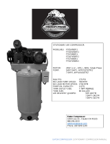
APP4V1043TP
19”
450
850
Per Application
Flywheel x Pump RPM /
Motor RPM = Pulley OD
*EXAMPLE: 19” x 850 (pump RPM) / 1750 motor RPM = suggested pulley size of 9.2”
6. This model of pump requires the use of two, ‘B’ groove belts.
7. Rotation of the pump should be clockwise when facing the pressure gauge, or counterclockwise from the
flywheel side.
8. Use care when aligning pump flywheel and motor pulley. Ensure center ridge on pump and pulley are in line.
Any direction out of line will cause premature belt wear.
9. When tightening belts check for belt deflection. Deflection should be no more than ½ inch.
Input lines for continuous run set up only. DO
NOT run lines from other sources to these
locations. Use only a manufacturer approved
pilot valve for continuous run use.
Proper belt tension is determined by pressing midway between the
motor pulley and the pump flywheel.

6
7.5/10 V4 PUMP MANUAL REV030921
Operation
1. The unit is shipped with pump break-in oil and should be ready to operate. Be sure to check for proper oil level
before running. Break in oil should be change after 100 Hours of operation (active pumping time). See
maintenance section for more information on oil changes and frequency.
2. Oil pressure on startup will vary due to ambient temperatures but should not exceed 100 PSI. Once the unit is
allowed to run a few cycles and come to optimal operating temperature, oil pressure should stabilize at 20-35
PSI. If the oil pressure remains high or drops too low, it can be adjusted as follows:
3. This pump is designed to operate with 3.80 Pints, or roughly 1.75 quarts of oil.
4. It is strongly advised to use only Airbase Industries piston compressor oil. Check with your warranty/extended
warranty guidelines to verify oil selection and use. Oil used in the pump must fall under the following criteria:
synthetic, SAE grade 30, non-detergent, piston compressor oil.
Oil level should be to the center of the red circle in the sight glass. Oil level WILL
drop once the unit turns on and oil begins to circulate.
When facing the oil pressure gauge. Look to the 7 o’clock
position. You will see an acorn nut (#32). Remove the acorn
nut and be careful to not lose the rubber seal (#4) sitting
behind it. Loosen but do not remove the set nut (#2). You will
see a flat head screwdriver slot in the end of the adjustor
(#16). To increase pressure, turn the adjustor clockwise; to
decrease pressure turn then adjustor counterclockwise. Turn
no more than ½ turn at a time. Then allow the unit to cycle to
measure the adjustment.
TAKE CARE when lowering pressure not to back the adjustor
out completely.
Once oil pressure is set, hold the adjustor (#16) in position
and retighten set nut (#2). Replace rubber seal (#4) and
reinstall acorn nut (#32).
FAILURE to reinstall acorn nut, seals, or set nuts can result in
oil leaks.
WARNING: Always make sure main power is off prior to touching belts or other
moving parts of the pump.

7
7.5/10 V4 PUMP MANUAL REV030921
Maintenance
1. Make sure repairs and service are done in a clean, dry, well-lit, and well-ventilated area.
2. When cleaning/blowing off, DO NOT exceed 30 PSI (2.1 bar) of pressure. NEVER use solvents for cleaning
purposes. Also use effective chip guarding and personal protective equipment per OSHA Standard 29 CFR
190.242(b).
3. Relieve all internal pressure prior to opening any line, fitting, hose, valve, drain plug, connection or any other
such component before refilling airline anti-icer systems with antifreeze compound.
4. Maintenance Schedule.
Item
Frequency
Comment
Cleanliness
Daily
Keep the pump and the surrounding area clean. Wipe off oil, spills, and
dirt/dust.
Oil Level
Daily
Check oil level while the power is OFF. If oil is low add to fill point. If
level is high, drain off oil.
Belt
Monthly
Verify belt tension. Replace if excessively loose or damaged.
Environment
Quarterly (four
times per year)
Air temperature should not exceed recommended levels. Humidity
where pump is stored should not exceed 70%. Consider relocating
pump if these conditions cannot be met.
Entire Pump
Yearly
Lock unit out and detail clean.
Air Filter(s)
See Comments
Air filters should be changed after the first 100-hour break in period
and every 90 days after that. The frequency will increase in
environments with air contaminants such as dust, paint, dirt, etc.
Oil
See Comments
Oil should be changed after the first 100-hour break in period and
every 90 days after that. This will increase in frequency depending on
actual pump use and hours unit is running.
Oil Filter
See Comments
The oil filter on the unit should be pulled and cleaned with every oil
change.
WARNING: Disconnect, tag, and lock out power source the release all pressure from the
system prior to install, service, or relocation.
WARNING: Disconnect, tag, and lock out power source the release all pressure from the
system prior to install, service, or relocation.

8
7.5/10 V4 PUMP MANUAL REV030921
5. How to change pump oil:
6. Oil is fill is located on the ‘Y’ shaped breather stem coming from the crank case. The fill is the center ¾” plug
located at the intersection of the ‘Y’. Pour oil slowly to avoid back fill into the breather and to allow oil a chance
to settle in the crank.
Oil Disposal
Compressor oil is not trash and MUST NOT be disposed of in regular trash or discarded into the environment. You MUST
dispose of waste oil from your unit per all applicable federal, state, and/or local codes. Failure to do so may damage the
environment and subject yourself and/or your business to fines and legal issues.
To drain oil:
1. Remove the oil fill cap.
2. Open Oil drain valve and allow oil to drain
naturally from pump.
3. Remove oil filter and clean with a mild solvent.
4. When reinstalling oil filter ensure gasket
alignment to prevent oil leaks.

9
7.5/10 V4 PUMP MANUAL REV030921
Pump Explosion/Parts List

10
7.5/10 V4 PUMP MANUAL REV030921

11
7.5/10 V4 PUMP MANUAL REV030921

12
7.5/10 V4 PUMP MANUAL REV030921

13
7.5/10 V4 PUMP MANUAL REV030921

14
7.5/10 V4 PUMP MANUAL REV030921

15
7.5/10 V4 PUMP MANUAL REV030921

16
7.5/10 V4 PUMP MANUAL REV030921

17
7.5/10 V4 PUMP MANUAL REV030921

18
7.5/10 V4 PUMP MANUAL REV030921
Troubleshooting
Some pump issues can be fixed simply by verifying the following guide. It is advised to go through the guide prior to
calling technical support to help expedite the assistance process.
Issue
Action
Pump does not run
Check unit power supply.
Pump cycles frequently
Check for leaks in facility/shop air lines or air system. Check for stuck tools or
machine leaks. Check pressure settings and PSI cycle settings on switch.
Pump will not reach pressure
Check CFM consumption of machines to ensure they do not exceed pump
capability. Ensure pump cycles within its duty cycle, 60% run. 40% rest.
Check tools for CONSTANT CFM rating, not average. Average ratings do not
reflect consumption and are often 66% lower than actual CFM consumption.
Check for leaks in air lines.
Oil level low
Verify oil level while unit is off and cool. Top oil off and monitor oil level. If it
drops again check for oil leaks and check correct oil is being used
Pump is running loud
Ensure bolts holding pump to mounting surface are snug.
Check oil pressure if there is no oil pressure shut unit down and contact
customer support.
Black dust is all over my pump area
Check belt alignment and tension. The black dust is rubber from belt wear. If
needed replace belts.
Right or left pop off valve flutters
Swap pop off with other banks pop off (right to left, DO NOT swap to center
cooler pop off). If the issue continues, check your high-pressure intake valve
and high-pressure exhaust valve for blockages or debris. Contact customer
support for replacement parts.
Oil leaks from breather
Remove and re-thread tape fittings in breather, clean fittings of excess oil.
Reinstall fittings and restart operation. Some oil blow by is expected during
normal break in period.
Air leaks from breather/filters when
pump is not in motion
Verify pump is plumbed to a check valve, air can be back feeding from tank if
no check valve is present.
Pull check valve and check for debris. Blockages in check valve allow air to
slowly leak back towards the pump. Replace check valve if needed.
Getting oil blow by
Verify pump has passed the break in time: 150-200 hours of active run time.
Ensure unit is not running in continuous mode prior to break in period being
completed (this can cause increase blow by during break in). For cases after
break in period contact customer support.

19
7.5/10 V4 PUMP MANUAL REV030921
Warranty Statement
• Standard Warranty: That each compressor bare pump is free from defects in material, workmanship, and parts for *1 year from
the date of delivery. Manufacturer is not responsible for downtime during warranty service. If downtime is necessary, it is at the
owner’s discretion, obligation, and expense, to have a redundant compressor. After one year, purchaser is required to return pump
to manufacturer to avoid core charge. Parts shipped for warranty repairs shall only include ground freight charges for the first 90
days of the warranty period, thereafter owner is responsible for all freight charges of parts and/or total pump replacement if
necessary being shipped for warranty fulfillment. Any and all express shipping charges of warranty parts would be at the owner’s
expense. Standard technical assistance is provided at no charge during and after the standard warranty period.
*Standard warranty has no obligation to maintain warranty status, warranty will expire one year from date
of delivery. Please see available options below to extend your warranty.
• 5 Year Extended Warranty: Manufacturer will extend your standard 1-year warranty to full 5 years when you opt to register for the
extended warranty plan that includes using our SMART OIL™ and following all routine maintenance set forth. Parts shipped for
warranty repairs shall only include ground freight charges for the first 90 days of the warranty period, thereafter owner is
responsible for all freight charges of parts and/or total pump replacement if necessary being shipped for warranty fulfillment. Any
and all express shipping charges of warranty parts would be at the owner’s expense. This plan includes our advanced technical air
support. Smart Tech Support provides you with the highest level of technical support.
Required maintenance schedule to maintain warranty status.
➢ All pumps are shipped with break-in oil and must be changed no less than 70 hours to insure gasket seating.
➢ After the 100 hours of break-in, you must change the oil.
➢ Thereafter Oil Should be changed every 6 months or 1000 hours whichever occurs first.
➢ Always maintain proper oil level in unit. If the unit runs out of oil due to neglect the warranty will be void.
➢ Use only Eaton approved oils in your pump, or your warranty is void.
➢ All stock orders by vendor/purchaser are required to buy two service kits at the time of purchase.
➢ All stocking orders will have a 6-month grace period for warranty registration. After that time, the unit must be registered, or
warranty may be void.
Warranty shall not apply, and manufacturer shall not be responsible nor liable for:
• Routine service such as oil changes, filter replacements, gasket tightening to correct oil seepage or drive belt tightening and valve
cleaning and are not covered under warranty.
• Consequential damages such as but not limited to cost of loss of business, product damage, or down time.
• Acts of nature, over abuse, malicious destruction, improper maintenance, undersized equipment
• Deviation from operating instructions or specifications
• Exceeding 70% duty cycle resulting in overheating and excessive wear and tear
• Any malfunction of reciprocating pump caused by failure or improper use and/or maintenance of other compressor components
manufactured by others.
• Normal wear and tear parts included but not limited to valves (intake/suction, check, blowdown, thermo, pop off, unloader), and ball
valves. Belts, shaft seals, load/unloader solenoids, sensors (temperature or pressure), Electrical contractors and relays, and any parts
with a routine maintenance schedule
Warranty shall be voided under the following conditions: Exposing electrical components to rain or water or installing the unit in a
hostile environment such as acid vapors or any caustic or abrasive matter that may be ingested into the pump or installing the unit in an enclosed
area where lack of cooling ventilation is present, such as in boiler or equipment rooms where the ambient air exceeds 110F.
/