Page is loading ...

Inverter Y Single Split E Series
A5LCY - E - 2010
A5LCY 10 ER
A5LCY 15 ER
Models:
Revise 1

Revision Table
Code Subject
Amendment on
Manual’s Page No.
Date
A5LCY-ER-2010-0001 Amendment on Electrical Data 26 16.6.2011
Amendment Sheet
Manual : Inverter Y Single Split E Series Code : A5LCY-E-2010 – 0001
Subject : Model A5LCY10/15ER
Description : Amendment on Electrical Data

Table of Contents A5LCY-E-2010
Contents
Nomenclature......................................................................................................................1
Indoor Unit .....................................................................................................................1
Outdoor Unit ..................................................................................................................2
Product Line-Up ..................................................................................................................3
Features...............................................................................................................................5
Application Information .....................................................................................................6
Operating Range ...........................................................................................................6
Refrigerant Circuit Diagram ...........................................................................................7
Controller ......................................................................................................................8
Installation Guideline .....................................................................................................9
Engineering & Physical Data ...........................................................................................21
General Data - Heat pump ..........................................................................................21
Components Data - Heat pump ...................................................................................23
Safety Devices Data ....................................................................................................24
Outline and Dimension ....................................................................................................25
Electrical Data ...................................................................................................................26
Wiring Diagram .................................................................................................................27
Service and Maintenance.................................................................................................28
Troubleshooting ...............................................................................................................31
Exploded View and Part List ...........................................................................................38

Nomenclature A5LCY-E-2010
1
Nomenclature
Indoor Unit
A 5 WM Y 10 K R
Brand
A : Acson
Refrigerant
5 : R410A
Model Name
WM : Wall Mounted
Inverter System Type
Y : Y series
Capacity Index
10
15
: 10,000 Btu/h
: 15,000 Btu/h
Chassis
K : K Series
Model Type
“ “
R
: Omitted if cooling only
: Heatpump

A5LCY-E-2010 Nomenclature
2
Outdoor Unit
A 5 LC Y 10 E R
Brand
A : Acson
Refrigerant
5 : R410A
Model Name
LC : Single Split Condensing Unit
Inverter System Type
Y : Y series
Capacity Index
10
15
: 10,000 Btu/h
: 15,000 Btu/h
Chassis
E : E Series
Model Type
“ “
R
: Omitted if cooling only
: Heatpump

3
Product Line-Up A5LCY-E-2010
Product Line-Up
Indoor Unit
A5WMY-K Series
A5WMY
Nomenclature
Classifi cation
Handset
PCB
Air Purifi cation
Fan Motor
Marking
Others
iAPJ2
2P206569-4
Saranet Filter
Titanium Apatite Photocatalytic
Filter
DC Fan Motor
CE
EUROVENT
HEATPUMP
10KR
-XXXXXXX
15KR
-XXXXXXX

4
A5LCY-E-2010 Product Line-Up
Outdoor Unit
A5LCY-E Series
A5LCY
Nomenclature
Classifi cation
PCB
Refrigerant
Control
Fin
Safety Devices
Compressor
Fan Motor
Marking
Others
2P257375-1
Cap Tube
EXV
Gold Coated
Blue Coated
Bare Fin
Overload Relay
DC Inverter Swing Compressor
DC Fan Motor
CE
EUROVENT
HEATPUMP
10ER - X X X X X X X X
15ER - X X X X X X X X

5
Features A5LCY-E-2010
Features
Self Diagnosis
The microprocessor provides the possibility to detect and diagnose any fault or malfunction that occurs in the
system. The error will be refl ected by the blinking of the LED lights at indoor unit and by wireless handset 7-
segment display.
Technology
Incorporate PI control to achieve more precise temperature control, faster and smoother response. Enhanced
design using
Electronic Expansion Valve to achieve optimum refrigerant control as compared to capillary tube.
Discharge pipe temperature control, high pressure limit control, input current control and heat sink
temperature control to improve reliability.
On / Off Button on Indoor Unit
On/Off button is provided on the unit. It can be used when the remote controller is missing or if its battery has
run out. (Note: This button can also be used for forced operation mode).
Auto Restart
Auto restart function allows the unit to automatic restart as the last setting condition when the power supply is
resumed after power failure. However, the compressor will restart randomly if more than one unit is installed
and sharing the same phase of power.
Wireless Remote Controller
The compact LCD transmitter is able to operate the air conditioner unit within the distance of 8 meters.
Fan speed can be set at high / medium / low / super low or automatic.
Night Set mode auto control will gradually increase or decrease the setting temperature to provide a
comfortable surrounding for sleeping.
Air fl ow direction can be controlled automatically.
Room temperature is controlled by electronic thermostat.
The delayed timer (from 1 to 9 hours) allows the air conditioner to be switched On and Off automatically
based on user settings.
Energy Saving
Equipped with energy saving selection to limit the maximum power consumption to just 700W. This feature is
also useful in preventing circuit breakers from being overloaded due to the use of multiple indoors and other
electrical devices. This new series is also designed with Standby Electricity Saving Function to reduce the
power consumption when unit is not in used.
•
•
•
•
•
•
•
•
•

6
A5LCY-E-2010 Application Information
Application Information
Operating Range
Ensure the operating temperature is in allowable range.
Heatpump
Heating
Outdoor temp. (°CWB)
Indoor temp. (°CDB)
Cooling
Outdoor temp. (°CDB)
Indoor temp. (°CWB)
-15
10 30
20
Standard
point
Caution :
The use of your air conditioner
outside the range of working
temperature and humidity can result
in serious failure
.
10
35
46
14 2319
20
6
STD
STD

7
Application Information A5LCY-E-2010
Refrigerant Circuit Diagram
Model: A5LCY 10ER - A5WMY 10KR
A5LCY 15ER - A5WMY 15KR
OUTDOOR TEMPERATURE
THERMISTOR
FIELD PIPING
GAS STOP
VALVE
7.0CuT
FIELD PIPING
(9.5CuT)
MUFFLER
HEAT EXCHANGER
THERMISTOR
PROPELLER FAN
6.4CuT
4.8CuT
HEAT EXCHANGER
FAN
MOTOR
9.5CuT
MUFFLER
WITH
FILTER
6.4CuT
M
TuC5.9
TuC0.7
DISCHARGE PIPE
THERMISTOR
LIQUID
STOP
VALVE
OUTDOOR UNIT
(6.4CuT)
9.5CuT
7.0CuT
MUFFLER
ACCUMULATOR
6.4CuT
MOTOR OPERATED
VALVE
STRAINER
6.4CuT
7.0CuT
COMPRESSOR
9.5CuT
FOUR WAY
VALVE
ON:HEATING
HEATING
7.0CuT
CROSS FLOW FAN
7.0CuT
7.0CuT
FAN MOT OR
HEAT EXCHANGER
9.5CuT
4.8CuT
INDOOR UNIT
COOLING
M
REFRIGERANT FLOW
7.0CuT
THERMISTOR
ON HEAT EXCH.

8
A5LCY-E-2010 Application Information
Controller
iAPJ2
Operation Guide
1 Signal transmitter:
It sends signals to the indoor unit.•
2 Display (LCD):
It displays the current settings.
(In this illustration, each section is shown
with its displays on for the purpose of
explanation.).
•
•
•
•
3 ECONO button:
ECONO operation•
4 POWERFUL button:
POWERFUL operation•
5 TEMPERATURE adjustment button:
It changes the temperature setting.•
6 ON/OFF button:
Press this button once to start operation.
Press once again to stop it.
•
•
7 MODE selector button:
It selects the operation mode.
(AUTO/DRY/COOL/HEAT/FAN)
•
8 FAN setting button:
It selects the airfl ow rate setting.•
9 SWING button:
Adjusting the airfl ow direction.•
10 COMFORT AIRFLOW button:
COMFORT AIRFLOW operation•
11 ON TIMER button:
12 OFF TIMER button:
13 TIMER CANCEL button:
It cancels the timer setting.•
1
6
2
10
9
8
5
13
4
3
7
12
11

9
Application Information A5LCY-E-2010
Installation Guideline
Safety Precautions
WARNING
CAUTION
Installation and maintenance should be performed by
qualifi ed persons who are familiar with local code and
regulation, and experienced with this type of appliance.
All fi eld wiring must be installed in accordance with the
national wiring regulation.
Ensure that the rated voltage of the unit corresponds
to that of the name plate before commencing wiring
work according to the wiring diagram.
The unit must be GROUNDED to prevent possible
hazard due to insulation failure.
All electrical wiring must not touch the refrigerant
piping or any moving parts of the fan motors.
Confi rm that the unit has been switched OFF before
installing or servicing the unit.
Disconnect from the main power supply before
servicing the air conditioner unit.
DO NOT pull out the power cord when the power is
ON. This may cause serious electrical shocks which
may result in fi re hazards.
Keep the indoor and outdoor units, power cable and
transmission wiring, at least 1m from TVs and radios,
to prevent distorted pictures and static. {Depending on
the type and source of the electrical waves, static may
be heard even when more than 1m away}.
•
•
•
•
•
•
•
•
•
Please take note of the following important points
when installing.
Do not install the unit where leakage of fl ammable
gas may occur.
If gas leaks and accumulates around the unit, it
may cause fi re ignition.
Ensure that drainage piping is connected properly.
If the drainage piping is not connected properly,
it may cause water leakage which will dampen
the furniture.
Do not overcharge the unit.
This unit is factory pre-charged. Overcharge will
cause over-current or damage to the compressor.
Ensure that the unit’s panel is closed after service
or installation.
Unsecured panels will cause the unit to operate
noisily.
Sharp edges and coil surfaces are potential
locations which may cause injury hazards. Avoid
from being in contact with these places.
Before turning off the power supply, set the remote
controller’s ON/OFF switch to the “OFF” position
to prevent the nuisance tripping of the unit. If this is
not done, the unit’s fans will start turning automatically
when power resumes, posing a hazard to service
personnel or the user.
Do not operate any heating apparatus too close to the
air conditioner unit. This may cause the plastic panel to
melt or deform as a result of the excessive heat.
Ensure the color of wires of the outdoor unit and
the terminal markings are same to the indoors
respectively.
IMPORTANT : DO NOT INSTALL OR USE THE
AIR CONDITIONER UNIT IN A LAUNDRY ROOM.
Do not use joined and twisted wires for incoming
power supply.
•
•
•
•
•
•
•
•
•
•
•
NOTICE
Disposal requirements
Your air conditioning product is marked with this symbol. This means that electrical and electronic products
shall not be mixed with unsorted household waste.
Do not try to dismantle the system yourself: the dismantling of the air conditioning system, treatment of
the refrigerant, of oil and of other parts must be done by a qualifi ed installer in accordance with relevant
local and national legislation. Air conditioners must be treated at a specialized treatment facility for re-use,
recycling and recovery. By ensuring this product is disposed of correctly, you will help to prevent potential
negative consequences for the environment and human health. Please contact the installer or local authority
for more information.
Batteries must be removed from the remote controller and disposed of separately in accordance with relevant
local and national legislation.

10
A5LCY-E-2010 Application Information
Installation Diagram
A
Screws
(M4 × 16L)
Service lid
Opening service lid
Service lid is opening/closing type.
Opening method
1) Remove the service lid screws.
2) Pull out the service lid diagonally
down in the direction of the arrow.
3) Pull down.
Wrap the insulation pipe with
the finishing tape from bottom
to top.
Cut thermal insulation
pipe to an appropriate
length and wrap it with
tape, making sure that no
gap is left in the insulation
pipe’s cut line.
Caulk
pipe hole
gap
with putty.
Mounting
plate
Clip
Mark (rear side)
Bottom frame
Front grille
How to attach the indoor unit
Hook the claws of the bottom frame
to the mounting plate.
If the claws are difficult to hook,
remove the front grille.
How to remove the indoor unit
Push up the marked area (at the
lower part of the front grille) to
release the claws. If it is difficult to
release, remove the front grille.
The mounting plate
should be installed on a
wall which can support the
weight of the indoor unit.
30mm or more from ceiling
Front panel
50mm or more from walls
(on both sides)
Air filters
Titanium apatite photocatalytic
air-purifying filter (2)
A Mounting plate
B Mounting plate
fixing screw
(M4 × 25L)
Air filter
Titanium apatite
photocatalytic
air-purifying filter
Filter frame
Ta b
C
F Fixing screw for remote
controller holder
(M3 × 20L)
D
Wireless remote
controller
E
Remote
controller holder
Before screwing the
remote controller
holder to the wall,
make sure that
control signals are
properly received by
indoor unit.

11
Application Information A5LCY-E-2010
Indoor Unit Installation
1. Installing the mounting plate
The mounting plate should be installed on a wall which can support the weight of the indoor unit.
1) Temporarily secure the mounting plate to the wall, make sure that the panel is completely level, and mark
the boring points on the wall.
2) Secure the mounting plate to the wall with screws.
Recommended mounting plate retention spots and dimensions
•
770
Use tape measure
as shown.
Position the end of
a tape measure at
Keep here the piece cut out
from the unit for piping
unit: mm
Gas pipe end
* The removed pipe port cover can be
kept in the mounting plate pocket.
Removed pipe
port cover
A
Mounting plate
Through-
the-wall
hole Ǿ65mm
Recommended mounting plate
retention spots (5 spots in all)
Place a leveler
on raised tab.
41.3
41.3
241.7
54
330.5
241.7
160
54.5
50160
101120.5
331
203 247
Drain hose
position
Liquid pipe end
CAUTION
Set the piping length from
1.5m to 15m.
Wrap the insulation pipe with
the finishing tape from bottom
to top.
In sites with poor drainage, use
block bases for outdoor unit.
Adjust foot height until the unit
is leveled. Otherwise, water
leakage or pooling of water may
occur.
Where there is a danger of the unit
falling, use foot bolts, or wires.
Allow space for piping
and electrical servicing.
250mm from wall
unit: mm
O.D. 9.5mm
Gas pipe
Liquid pipe
O.D. 6.4mm
20g/m
Max. allowable length
12m
15m
Max. allowable height
Additional refrigerant
required for refrigerant
pipe exceeding
10m in length.
*
Be sure to add the proper amount of additional refrigerant.
Failure to do so may result in reduced perfomance.
*
The suggested shortest pipe length is 1.5m, in order to avoid
noise from the outdoor unit and vibration.
(Mechanical noise and vibration may occur depending on how
the unit is installed and the environment in which it is used.)
1.5m
Min. allowable length
470
(Foot bolt-hole centres)
(From unit’s side)
96
(Foot bolt-hole
centres)
300
How to remove the stop
valve cover
Remove the screw on the
stop valve cover.
Slide the lid downward
to remove it.
How to attach the stop
valve cover
Insert the upper part of
the stop valve cover into the
outdoor unit to install.
Tighten the screws.
Stop valve cover
*

12
A5LCY-E-2010 Application Information
2. Boring a wall hole and installing wall embedded pipe
For walls containing metal frame or metal board, be sure to use
a wall embedded pipe and wall cover in the feed-through hole to
prevent possible heat, electrical shock, or fi re.
Be sure to caulk the gaps around the pipes with caulking material to
prevent water leakage.
1) Bore a feed-through hole of 65mm in the wall so it has a down
slope toward the outside.
2) Insert a wall pipe into the hole.
3) Insert a wall cover into wall pipe.
4) After completing refrigerant piping, wiring, and drain piping, caulk
pipe hole gap with putty.
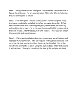
3. Installing indoor unit
In the case of bending or curing refrigerant pipes, keep the following
precautions in mind.
Abnormal sound may be generated if improper work is conducted.
1) Do not strongly press the refrigerant pipes onto the bottom frame.
2) Do not strongly press the refrigerant pipes on the front grille, either.
3-1. Right-side, right-back, or right-bottom piping
1) Attach the drain hose to the underside of the refrigerant
pipes with an adhesive vinyl tape.
2) Wrap the refrigerant pipes and drain hose together with an
insulation tape.
3) Pass the drain hose and refrigerant pipes through the
wall hole, then set the indoor unit on the mounting plate
hooks by using the markings at the top of the indoor unit
as a guide.
4) Open the front panel, then open the service lid.
(Refer to installation tips.)
5) Pass the inter-unit wiring from the outdoor unit through the
feedthrough wall hole and then through the back of the
indoor unit.
Pull them through the front side. Bend the ends of tie
wires upward for easier work in advance. (If the inter-unit
wiring ends are to be stripped fi rst, bundle wire ends with
adhesive tape.)
6) Press the bottom frame of the indoor unit with both hands
to set it on the mounting plate hooks. Make sure the wires
do not catch on the edge of the indoor unit.
•
•
•
Inside Outside
Caulking
Wall embedded pipe
(field supply)
Wall hole cover
(field supply)
Wall embedded pipe
(field supply)
φ
65
1)
2)
Right-bottom
piping
Right-back piping
Bind coolant pipe
and drain hose
together with
insulating tape.
Remove pipe port cover
here for right-side piping.
Remove pipe port cover
here for right-bottom piping.
Mounting plate
A
Wire guide
When stripping the
ends of inter-unit wiring
in advance, bind right ends
of wires with insulating tape.
Hang indoor unit’s hook here.
Inter-unit wiring
Mounting plate
A

13
Application Information A5LCY-E-2010
Remove pipe port cover here for left-bottom piping.
Remove pipe
port cover
here for left-
side piping.
Left-bottom piping
Left-side
piping
Left-back
piping
3-2. Left-side, left-back, or left-bottom piping
How to replace the drain plug and drain hose
• Replacing onto the left side
1) Remove the insulation fi xing screw on the
right and remove the drain hose.
2) Remove the drain plug on the left side
and attach it to the right side.
3) Insert the drain hose and tighten with
included insulation fi xing screw.
* (Forgetting to tighten this may cause water
leakages.)
Drain hose attachment position
* The drain hose is on the back of the unit.
Front side of unit
Attachment on the right side (factory default)
Attachment on the left side
esohniarDesohniarD
Insulation
fixing screw
Right sideLeft side
Insulation
fixing screw
1) Attach the drain hose to the underside of the refrigerant pipes
with adhesive vinyl tape.
2) Be sure to connect the drain hose to the drain port in place of a
drain plug.
3) Shape the refrigerant pipe along the pipe
path marking on the mounting plate.
4) Pass drain hose and refrigerant pipes
through the wall hole, then set the indoor
unit on mounting plate hooks, using the
markings at the top of indoor unit as a
guide.
5) Pull in the inter-unit wiring.
6) Connect the inter-unit piping.
7) Wrap the refrigerant pipes and drain hose together with insulation tape
as right fi gure, in case of setting the drain hose through the back of the
indoor unit.
8) While exercising care so that the inter-unit wiring do not catch indoor
unit, press the bottom edge of indoor unit with both hands until it is
fi rmly caught by the mounting plate hooks. Secure indoor unit to the
mounting plate with indoor unit fi xing screws (M4 × 12L).
3-3.Wall embedded piping
Follow the instructions given under left-side, left-back, or left-bottom
piping.
1) Insert the drain hose to this depth so it won’t be pulled out of the
drain pipe.
How to set drain plug.
No gap.
Do not apply lubricating
oil (refrigeration oil)
when inserting.
Application of causes
deterioration and drain
leakage of the plug.
Insert a hexagonal wrench (4mm).
Drain
hose
Caulk this hole
with putty or
caulking material.
Bind with vinyl
tape.
A
Mounting plate
Wrap insulating tape around the
bent portion of refrigerant pipe.
Overlap at least half the width of
the tape with each turn.
Refrigerant
pipes
Drain hose
Bottom frame
H Indoor unit fixing screw
M4 12L (2 point)
Mounting
plate
A
Inter-unit wiring
Inner wall
Vinyl chloride
drain pipe
(VP-30)
Drain hose50mm
or more
Insert drain hose
to this depth so
it won’t be pulled
out of drain pipe.
Outer wall

14
A5LCY-E-2010 Application Information
4. Wiring
1) STRIP WIRE ENDS (15MM).
2) MATCH WIRE COLOURS WITH TERMINAL NUMBERS ON INDOOR AND OUTDOOR UNIT’S TERMINAL BLOCKS AND FIRMLY SCREW
WIRES TO THE CORRESPONDING TERMINALS.
3) CONNECT THE EARTH WIRES TO THE CORRESPONDING TERMINALS.
4) PULL WIRES TO MAKE SURE THAT THEY ARE SECURELY LATCHED UP, THEN RETAIN WIRES WITH WIRE RETAINER.
5) IN CASE OF CONNECTING TO AN ADAPTER SYSTEM. RUN THE REMOTE CONTROL CABLE AND ATTACH THE S21. (REFER TO
5. WHEN CONNECTING TO A WIRED REMOTE CONTROLLER.)
6) SHAPE THE WIRES SO THAT THE SERVICE LID FITS SECURELY, THEN CLOSE SERVICE LID.
WARNING
Do not use tapped wires, stranded wires, extension cords, or starburst connections, as they may cause
overheating, electrical shock, or fi re.
Do not use locally purchased electrical parts inside the product. (Do not branch the power for the drain
pump, etc., from the terminal block.) Doing so may cause electric shock or fi re.
•
•
123
Terminal block
Electrical component box
Wire retainer
Use the specified
wire type.
Shape wires so that the
service lid will fit securely.
Firmly secure wire retainer so that
wires sustain no external stress.
1
2
3
123 LN
Use 2.0mm diameter wires.
H05RN
Firmly fix the wires with
the terminal screws.
Outdoor unit
Indoor
unit
Firmly fix the wires with
the terminal screws.

15
Application Information A5LCY-E-2010
5. Drain piping
1) CONNECT THE DRAIN HOSE, AS DESCRIBED RIGHT.
2) Remove the air fi lters and pour some water into the drain pan to check the water
fl ows smoothly.
3) If drain hose extension or embedded drain piping is required, use appropriate parts that match the hose front
end. [Figure of hose front end]
4) When extending the drain hose, use a commercially
available extension hose with an inner diameter of
16mm. Be sure to thermally insulate the indoor section
of the extension hose.
5) When connecting a rigid polyvinyl chloride
pipe (nominal diameter 13mm) directly to
the drain hose attached to the indoor unit
as with embedded piping work, use any
commercially available drain socket
(nominal diameter 13mm) as a joint.
The drain hose should
be inclined downward.
No trap is permitted.
Do not put the end
of the hose in water.
φ18φ16
φ16
The drain hose provided
to indoor unit.
Indoor unit
drain hose
φ16
Extension drain hose
Heat insulation tube
(field supply)
Commercially available drain
socket
(nominal diameter 13mm)
Commercially available rigid
polyvinyl chloride pipe
(nominal diameter 13mm)
The drain hose provided
to indoor unit.
φ18

16
A5LCY-E-2010 Application Information
05nahteroM05nahteroM
More than 150
More
than 100
More than 50 More than 100
Side view
1200
or less
Wall facing one side Walls facing two sides
Top view
Top view
unit: mm
More than 150
More than 300
More than 50
Walls facing three sides
Outdoor Unit Installation
Where a wall or other obstacle is in the path of outdoor unit’s intake or exhaust airfl ow, follow the
installation guidelines below.
For any of the below installation patterns, the wall height on the exhaust side should be 1200mm or less.
Pump Down Operation
In order to protect the environment, be sure to pump down when relocating or disposing of the unit.
1) Remove the valve cap from liquid stop valve and gas stop valve.
2) Carry out forced cooling operation.
3) After 5 to 10 minutes, close the liquid stop valve with a hexagonal wrench.
4) After 2 to 3 minutes, close the gas stop valve and stop forced cooling operation.
How to forced cooling operation mode
■ Using the indoor unit ON/OFF button
Press the indoor unit ON/OFF button for at least 5 seconds. (Operation will start.)
• Forced cooling operation will stop automatically after around 15 minutes.
To force a trial operation to stop, press the indoor unit ON/OFF button.
■ Using the main unit’s remote controller
1) Press “ON/OFF” button to turn on the system.
2) Press “TEMP” button (2 locations) and “MODE” button at the same time.
3) Press “MODE” button twice and select “ ”.
4) Trial operation terminates in approx. 30 minutes and switches into normal mode. To quit a trial operation,
press “ON/OFF” button.
CAUTION
When pressing the switch, do not touch the terminal block. It has a high voltage, so doing so may cause
electric shock.
After closing the liquid stop valve, close the gas stop valve within 3 minutes, then stop the forced
operation.
•
•
•
•
Gas
stop valve
Valve cap
Hexagonal
wrench
Close
Liquid
stop valve

17
Application Information A5LCY-E-2010
1
2
3
123
LN
Safety
breaker
16A
Earth leakage
circuit breaker
Earth
H05RN
Firmly fix the wires with
the terminal screws.
Outdoor unit
Indoor
unit
Power supply
50Hz 220-240V
Firmly fix the wires with
the terminal screws.
Use 2.0mm diameter wires.
1
2
3
1
2
3
Use the specified wire type and
connect it securely.
Firmly secure
wire retainer so
wire terminations
will not receive
external stress.
Shape wires so
that the stop
valve cover fit
securely.
Power supply
terminal block
Stranded wire
Round crimp-style
terminal
Electrical Wiring Connection
WARNING
Do not use tapped wires, stranded wires, extension cords, or starburst connections, as they may cause
overheating, electrical shock, or fi re.
Do not use locally purchased electrical parts inside the product. (Do not branch the power for the drain
pump, etc., from the terminal block.) Doing so may cause electric shock or fi re.
Be sure to install an earth leakage breaker. (One that can handle higher harmonics.) (This unit uses an
inverter, which means that it must be used an earth leakage breaker capable handling harmonics in order
to prevent malfunctioning of the earth leakage breaker itself.)
Use an all-pole disconnection type breaker with at least 3mm between the contact point gaps.
Do not turn on the safety breaker until all work is completed.
1) strip the insulation from the wire (20mm).
2) connect the connection wires between the
indoor and outdoor units so that the terminal
numbers match. tighten the terminal screws
securely. we recommend a fl athead
screwdriver be used to tighten the screws.
the screws are packed with the terminal
board.
Observe the notes mentioned below when wiring to the
power supply
terminal board.
Precautions to be taken for power supply wiring.
Use a round crimp-style terminal for connection to the power
supply
terminal board. In case it cannot be used due to unavoidable
reasons, be
sure to observe the following instruction.
Place the round crimp-style terminals on the wires up to the
covered part
and secure in place.
•
•
•
•
•
/