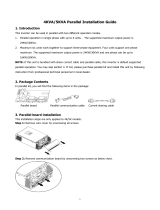
Must EP18-5048 Installation guide

Type
Installation guide

The Must EP18-5048 is a versatile and reliable device that offers a range of features to meet your energy needs. It excels in performance, with a maximum efficiency of 97.6% and an MPPT efficiency of 99.5%, ensuring optimal energy conversion from your solar panels. The wide input voltage range of 120-450VDC allows for compatibility with various solar panel configurations. Additionally, the built-in Wi-Fi and Bluetooth connectivity options provide convenient monitoring and control of your system.

The Must EP18-5048 is a versatile and reliable device that offers a range of features to meet your energy needs. It excels in performance, with a maximum efficiency of 97.6% and an MPPT efficiency of 99.5%, ensuring optimal energy conversion from your solar panels. The wide input voltage range of 120-450VDC allows for compatibility with various solar panel configurations. Additionally, the built-in Wi-Fi and Bluetooth connectivity options provide convenient monitoring and control of your system.

4KVA/5KVA
Parallel Installation Guide
4200-010235-0300
8. Trouble shooting
Situation
Solution
Fault
Code
Fault Event Description
80 CAN data loss
81 Host data loss
82
83
84
85
86
87
88
89
90 CAN ID setting Error
1.Check if communication cables are connected
well and restart the inverter.
2.If the problem remains, please contact your
installer.
1.Make sure all inverters share same groups of
batteries together.
2.If the problem remains, please contact your
installer.
The battery voltage of
each inverter isnot
the same.
Synchronization data loss
AC input voltage and
frequency are
detected different
AC output current
unbalance
AC output mode setting
is different
1.Check the utility wiring conncetion and restart
the inverter.
2.If the problem remains, please contact your
installer.
1.Restart the inverter.
2.If the problem remains, please contact your
installer
1.Switch off the inverter and check the DIP switch
setting.
2.If the problem remains, please contact your
installer.
Current feedback into the
inverter is detected.
The firmware version of
each inverter is not the
same.
The output current of each
inverter is different.
2.If the problem remains, please contact your
installer.
1.Update all inverter firmware to the same
version.
2.If the problem remains, please contact your
1.Restart the inverter.
2.If the problem remains, please contact your
installer.
9
8. Trouble shooting
1. Introduction
2. Package Contents
3. Mounting the unit
6. Fault code display
7. Commissioning
4. Wiring Connection
5. PV Connection
1
1
1
2
5
6
7
9
Table Of Contents
4-2. Support 3-phase equipment
4-1. Parallel Operation in Single phase 3
5
1.Switch off the inverter and check the DIP switch
setting.
2.If the problem remains, please contact your
1.Check if communication cables are connected
well and restart the inverter.
installer.
1. Introduction
2.
Package Contents
In the case, you will find the following items in the package:
Parallel communication cable
3.
Mounting the unit
When installing multiple units, please follow below chart.
NOTE:
the side and approx.
For proper air circulation to dissipate heat, allow a clearance of approx. 30 cm to
50 cm above and below the unit. Be sure to install each unit in the
same level.
This inverter can be used in parallel with two different operation modes.
30cm
50cm
30cm 30cm 30cm
50cm
Support three-phase equipment
Step 1: Check the following requirements before commissioning:
Correct wire connection
Ensure all breakers in Line wires of load side are open and each Neutral wires of
each unit are connected together.
Step 2: On the bottom panel of inverter ,there are 5 pins DIP switches, you can
set it as .follow Figure 2
LCD display in L1-phase
unit
LCD display in L2-phase
unit
LCD display in L3-phase
unit
Step 4: Switch on all AC breakers of Line wires in Grid. If Grid is detected and
three phases are matched with unit setting, they will work normally. Otherwise,
the AC icon will flash and they will not work in line mode.
LCD display in L1-phase
unit
LCD display in L2-phase
unit
LCD display in L3-phase
unit
Step 5: If there is no more fault alarm, the system to support 3-phase equipment
is completely installed.
Step 6: Please switch on all breakers of Line wires in load side. This system will
start to provide power to the load.
Note 1:To avoid overload occurring, before turning on breakers in load side, it s
better to have whole system in operation first.
Note 2: Transfer time for this operation exists. Power interruption may happen to
critical devices, which cannot bear transfer time.
1
8
(1). Parallel operation in single phase with up to 3 units. The supported maximum output
power is 15KVA(for 5KVA inverter)/12KVA (for 4KVA inverter).
(2). Maximum three units work together to support three-phase equipment. The
supported maximum output power is 15KVA(for 5KVA inverter)/12KVA (for 4KVA inverter).
NOTE: It's necessary to turn off the machines when setting the DIP switches.
Otherwise, the setting can not be programmed.
Step 3: Turn on all units sequentially
Figure 2
Inverter Inverter Inverter
,
Parallel board
12345
12345
O N
O N
7 .Commissioning
Parallel in single phase
Step 1:Check the following requirements before commissioning:
Correct wire connection
Ensure all breakers in Line wires of load side are open and each Neutral wires of
each unit are connected together.
Step 2: On the bottomt panel of inverter ,there are 5 pins DIP switches, you can
set it as .follow Figure 1
LCD display in Master unit LCD display in Slave unit
NOTE: Master and slave units are randomly defined.
Step 4: Switch on all AC breakers of Line wires in Grid. It's better to have all
inverters connect to Grid at the same time. If not, it will display fault 82 in
following-order inverters. However, these inverters will automatically restart.
If detecting AC connection, they will work normally.
4. Wiring Connection
The cable size of each inverter is shown as below:
Recommended battery breaker, cable and terminal size for each inverter:
WARNING: Be sure the length of all battery cables is the same. Otherwise, there will be
voltage difference between inverter and battery to cause parallel inverters not working:
2 units 3 units
Note 1: Also, you can use 40A breaker for only 1 unit,(50A for 5KVA), and each inverter
Note 2: Regarding three phase system, you can use 4 poles breaker, the rating is
up to the current of the phase which has the maximum units. Or you can follow
the suggestion of note 1.
27
NOTE 2: It's necessary to turn off the machines when setting the DIP switches.
Otherwise, the setting can not be programmed.
Step 3: Turn on each unit.
Recommended Grid and Load cable size for each inverter:
Model AWG no. Torque
1.4~1.6Nm
1.4~1.6Nm
4KVA
5KVA
10AWG
8AWG
You need to connect the cables of each inverter together. Take the battery cables
for example: You need to use a connector or bus-bar as a joint to connect the
battery cables together, and then connect to the battery terminal. The cable size
used from joint to battery should be X times cable size in the tables above. “X”
indicates the number of inverters connected in parallel. Regarding Grid and Load,
please also follow the same principle.
CAUTION!! Please install the breaker at the battery and Grid side. This will
ensure the inverter can be securely disconnected during maintenance and fully
protected from over current of battery or Grid. The recommended mounted
location of the breakers is shown in the figures in 4-1 and 4-2.
*If you want to use only one breaker at the battery side for the whole system, the
rating of the breaker should be X times current of 1 unit. “X” indicates the number
of inverters connected in parallel.
Recommended breaker specification of Grid side with single phase:
Step 5: If there is no more fault alarm, the parallel system is completely installed.
Step 6: Please switch on all breakers of Line wires in load side. This system will
start to provide power to the load.
Figure 1
Inverter Inverter Inverter
NOTE 1: If there are two inverter in parallel, you Only need to set inverter and
inverter .
Model
4KVA
5KVA
80A/230VAC
100A/230VAC
120A/230VAC
150A/230VAC
has a breaker at its AC input.
BATTERY
6. Fault code display:
Fault Code Fault Event Icon on
80
81
82
83
84
85
86
87
CAN fault
Host loss
Synchronization loss
Battery voltage detected different
AC input voltage and frequency
detected different
AC output current unbalance
AC output mode setting is different
Recommended battery capacity
Communication Connection
WARNING! Be sure that all inverters will share the same battery bank. Otherwise,
the inverters will transfer to fault mode.
4-1. Parallel Operation in Single phase
Two inverters in parallel:
Power Connection
3
6
88 Firmware version inconsistent
89 Current sharing fault
90 CAN ID setting Error
INVERTER : 1 of bottom
key 2,3,4,5 of top
Setting the key DIP Switch to the position, and the
DIP Switch to the position.
INVERTER : key 2 of DIP bottom
key of Switch top
Setting the Switch to the position, and the
1,3,4,5 DIP to the position.
Power feedback protection
BATTERY
BATTERY
5. PV Connection
Please refer to user manual of single unit for PV Connection.
CAUTION: Each inverter should connect to PV modules separately.
Three inverters in parallel:
Power Connection
4-2. Support 3-phase equipment
One inverter in each phase:
Power Connection
45
INVERTER : 1 of bottom
key 2,3,4,5 of top
Setting the key DIP Switch to the position, and the
DIP Switch to the position.
INVERTER : key 2 of DIP bottom
key of Switch top
Setting the Switch to the position, and the
1,3,4,5 DIP to the position.
INVERTER : key 1,2 of DIP bottom
key of Switch top
Setting the Switch to the position, and the
3,4,5 DIP to the position.
INVERTER : 1,3 of bottom
key 2,4,5 of top
Setting the key DIP Switch to the position, and the
DIP Switch to the position.
INVERTER : key 2,3 of DIP bottom
key of Switch top
Setting the Switch to the position, and the
1,4,5 DIP to the position.
INVERTER : key 1,2,3 of DIP bottom
key of Switch top
Setting the Switch to the position, and
the 4,5 DIP to the position.
NOTE: No connect 3-phase equipment of delta connection
  • Page 1 1
  • Page 2 2
  • Page 3 3
  • Page 4 4
  • Page 5 5
  • Page 6 6

Must EP18-5048 Installation guide

Type
Installation guide

The Must EP18-5048 is a versatile and reliable device that offers a range of features to meet your energy needs. It excels in performance, with a maximum efficiency of 97.6% and an MPPT efficiency of 99.5%, ensuring optimal energy conversion from your solar panels. The wide input voltage range of 120-450VDC allows for compatibility with various solar panel configurations. Additionally, the built-in Wi-Fi and Bluetooth connectivity options provide convenient monitoring and control of your system.

Ask a question and I''ll find the answer in the document

Finding information in a document is now easier with AI