-1--3--4-
-2-
Warning
TURBO TIMER HE 24V
Keeps the vehicle idling for a preset period
of time after ignition has been turned off.
Domestic heavy equipment.
DC24 V Negative Ground Vehicles.
PRODU C T
USE
APPLICATION
41001-AK013 P A R T No.
Warning
Caution
E05131-K00180-00
August, 2022
Ver.3-1.01
Pursuing the Ultimate in Engine Performance and Efficiency.
HKS Company Limited
Warning
Caution
Parking Brake
Parking Brake Wire
Splice
This manual assumes that you have and know how to use the tools and
equipment necessary to safely perform service operations on your vehicle.
This manual assumes that you are familiar with typical automotive systems
and basic service and repair procedures. Do not attempt to carry out the
operations shown in this manual unless these assumptions are correct.
Always have access to a factory repair manual. To avoid injury, follow the
safety precautions contained in the factory repair manual.
● This manual indicates items that require careful attention in order to
install this product safely, and lists precautions to avoid any possible
damage and/or accidents.
● This product was designed for and tested on a factory-spec vehicle or
a vehicle equipped with other HKS products. Performance and/or safety
cannot be guaranteed if this product is installed onto other inapplicable
vehicles.
● For any lost, defective and/or damaged parts, contact your retailer/dealer
to order.
● HKS will not be held responsible for any damage caused by incorrect
installation, mishandling, and/or misuse, nor for damages caused by
modifications to or dismantling of this product.
● This product will only operate on a vehicle with DC24 V negative ground.
● Use this product with a relay capacity of 3 A or less.
● The specifications of this product are subject to change without notice.
● This manual is subject to be revised without notice.
1.NOTICE
2.TABLE OF CONTENTS
INSTRUCTION MANUAL
3.SAFETY INSTRUCTIONS
● Make sure to work on the vehicle in a well-ventilated area to prevent
possible explosion or fires.
● To avoid possible accidents, do not mount the unit in areas where
the driver may become distracted during driving.
● Make sure to secure wires routed inside the vehicle to avoid possible
accidents where the driver's feet may become caught or tangled in
wiring.
● Make sure to disconnect the cable from the negative terminal of the
battery to avoid possible damage to other electronics parts and/or a
fire caused by a short circuit.
● Properly disconnect all connectors/harnesses by holding the
connectors and not the wires. Failure to do so may damage the
wires and/or connectors and can lead to shorts.
8. NAMES AND FUNCTIONS ‥‥‥‥ P6
9. OPERATION‥‥‥‥‥‥‥‥‥‥ P6
10. OPTIONAL PARTS LIST ‥‥‥‥‥ P7
11. TROUBLESHOOTING ‥‥‥‥‥‥ P7
12. PRODUCT SPECIFICATIONS‥‥‥ P8
13. INSTRUCTION MANUAL
REVISION HISTORY ‥‥‥‥‥‥ P8
1. NOTICE ‥‥‥‥‥‥‥‥ P1
2. TABLE OF CONTENTS ‥‥ P1
3. SAFETY INSTRUCTIONS ‥ P1
4. PREFACE ‥‥‥‥‥‥‥ P2
5. PARTS LIST ‥‥‥‥‥‥ P3
6. INSTALLATION ‥‥‥‥‥ P3
7. AFTER INSTALLATION‥‥ P5
● Do not operate the Turbo Timer while driving. Always operate the
Turbo Timer while the vehicle is parked in a safe location.
● When the Turbo Timer is operational (timer countdown idle with the
ignition off), do not leave the vehicle until after the engine has
completely shut off.
● Make sure the parking brake is applied, and the gear selector is in
neutral (for MT) or in the Park (P) position (for AT), prior to starting
the Turbo Timer to prevent serious accidents.
Do not operate the Turbo Timer indoors or in poorly-ventilated areas
to prevent carbon monoxide poisoning from exhaust gases.
● If any unusual noises, scents, and/or vibrations are noticed while
driving, stop using this product and consult your HKS Authorized
Dealer immediately.
● If for any reason the engine does not shut off after the timer
countdown, turn off the Turbo Timer immediately, or disconnect the
harness to prevent possible fires.
● Use this product with a relay capacity of 3 A or less. Otherwise, if
other electrical equipment (such as power windows) is used while
this product is operational, it may cause fire and/or damage to the
electrical equipment.
● Do not install this product by yourself unless you have and know
how to use the tools and equipment necessary to safely perform
service operations on your vehicle.
● Do not modify, disassemble, and/or repair the product and supplied
parts to avoid any damage to the vehicle.
● Handle the parts with extra care at all times.
● Avoid allowing oil and/or water to enter the unit to prevent
malfunctions that may cause damage to the engine.
● To avoid possible malfunction and damage to the engine, install the
unit away from areas of excessive heat or water/moisture.
● Make sure all connections and wiring are correct to prevent electric
shocks, shorts, or damage to the vehicle.
● When using a splice, make sure to insulate the portion where a
splice is installed using an insulating tape.
Failure to do so may cause vehicle damage and/or burnout.
● Connect the ground wire to the screw that is used for the vehicle's
chassis ground.
● If the product or the vehicle with the product does not operate
properly, consult your retailer/dealer immediately.
・Daily maintenance of the vehicle is the responsibility of the owner/user.
・Refer to the factory service manual when removing factory parts.
・Do not lose and/or damage any removed factory parts.
・Make sure to use the appropriate tools when tightening all nuts and bolts.
・Make sure not to damage the factory wiring when installing this product.
4.PREFACE
The number one cause of turbo failure is oil "coking". Oil "coking" occurs
when a turbocharger is not properly cooled down and the oil that normally
lubricates the center cartridge heats up and forms solidified oil deposits.
A turbo timer allows an engine to idle for a preset time after the ignition
key has been turned to the off position and removed. --- By allowing a
turbocharged engine to idle, oil continues to pass through the turbo until
it has cooled down to the point where oil "coking" will not occur, thereby
prolonging the life of the turbocharger. The HKS TURBO TIMER has the
following functions.
● Turbo Timer function
・5 time ranges selectable between 1, 3, 5, 10, and 30 min.
● Low-voltage Protective Function
・Timer stops when the battery voltage decreases to 18 V or lower.
● Safety Circuit Function
・This function prevents the vehicle to be driven after the Turbo Timer
countdown has started.
●If the vehicle is driven after the Turbo Timer countdown has started,
the Turbo Timer and engine will automatically shut off. Do not
attempt to drive the vehicle in this state.
● DC24 V
・This product operates only on DC24 V negative ground vehicles. Do not
install on 12 V vehicles.
In order to install this product, the following tools are required:
Wrench, Nippers, Screwdriver, Crimping Tool, Insulating Tap (vinyl tape),
Tester, etc.
● The safety circuit wiring must be performed, as the Turbo Timer will not
operate without it.
● After completing the installation, confirm the safety circuit functions properly.
● Do not connect the black ground wire to the power supply wires
(such as IG, +B, and/or ACC). It may cause damage to the Turbo Timer.
6.INSTALLATION
5.PARTS LIST
If there is one Parking Brake Wire
(1) Connect the gray wire from the
Turbo Timer to the supplied gray
parking brake wire.
(2) Using the supplied splice connector,
connect the supplied gray parking brake
wire to the vehicle's parking brake wire.
If there are two Parking Brake Wires
(1) Connect the gray wire from the Turbo Timer to the supplied gray
parking brake wire.
(2) Turn the key switch on. (Do not start the engine.)
(3) Using a multi-meter, find the wire that reads 0 V when the parking brake
is engaged, and 24 V when the parking brake is disengaged.
(4) Using the supplied splice, connect the gray parking brake
wire to the vehicle's parking brake wire found in (3).
6-4. Safety Circuit Wiring Connection
6-1. How to use the splice
(4)
Insulate with electrical tape.
(2)
Twist wires together.
(3)
Stake the wires using a splice.
(1)
Strip the cover 5 mm.
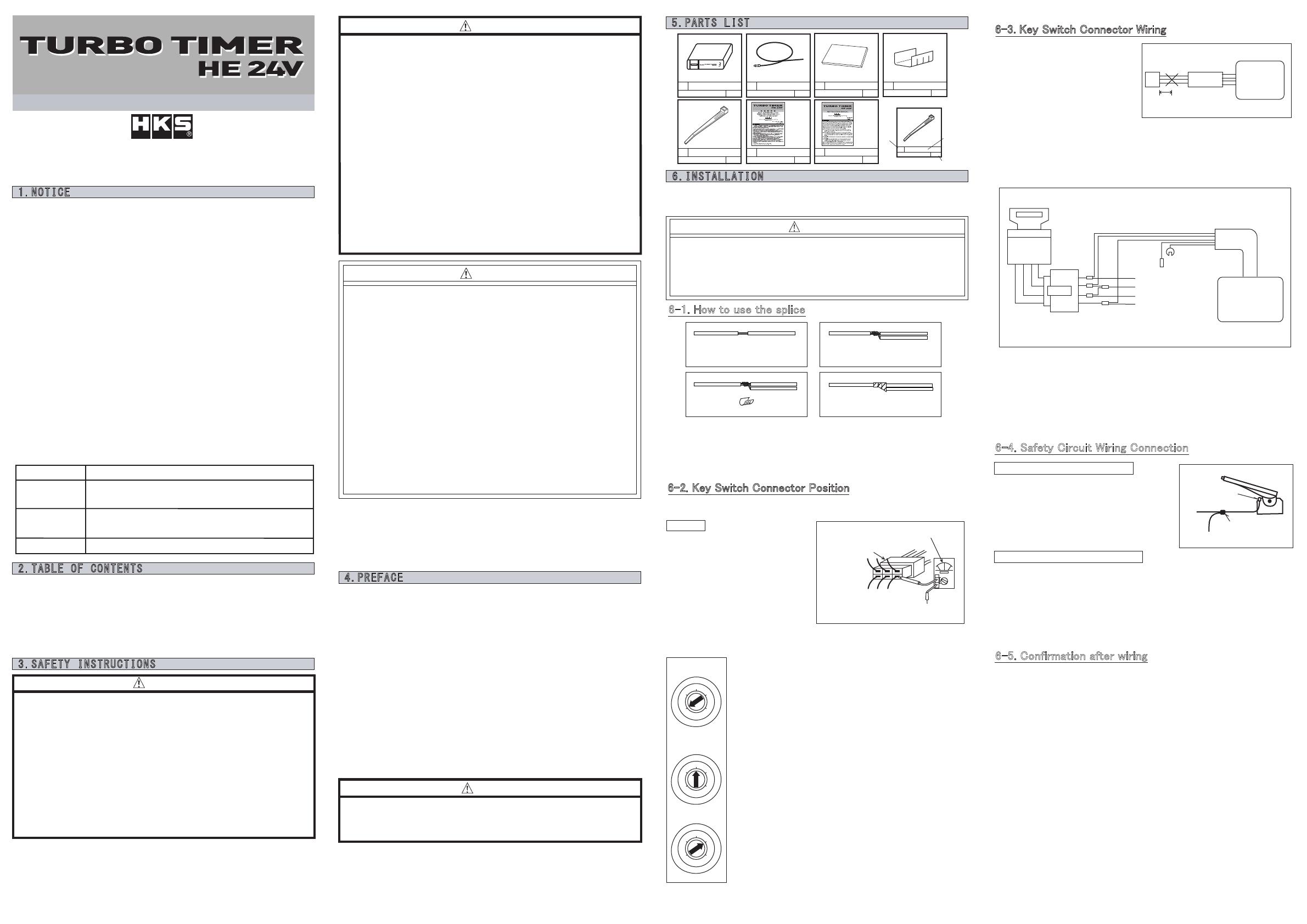
6-2. Key Switch Connector Position
Use a tester to check the + B, ACC, IG1, and IG2 wiring contained
in the key switch connector.
ADVICE
・ When searching for + B, ACC,
IG1, and IG2 lines, connect the
negative side of the tester to
the metal part of the body
(where the body is securely
grounded).
・ When searching for + B, ACC,
IG1, and IG2 lines, set the tester
to the DC voltage measurement range.
・ It is convenient to draw the position of the connector line in the figure.
L
O
C
K
O
F
F
A
C
C
O
N
S
T
A
R
T
L
O
C
K
O
F
F
A
C
C
O
N
S
T
A
R
T
L
O
C
K
O
F
F
A
C
C
O
N
S
T
A
R
T
●Check + B (constant power line)
(a)Set the engine key to the "lock" or "OFF" position.
(b)Place the positive side of the tester on the metal
part at the base of the wire of the key switch
connector as shown in Fig. 1.
・The line where the tester's needle shook is + B.
(c)Some vehicles have multiple + B, so please check all
of them.
●Checking ACC (accessory power line)
・If the key does not have an ACC position, there is no
need to check.
(a)Set the engine key to the "ACC" position.
(b)Except for the confirmed + B, check the ACC in the
same way as for + B.
●Check IG1 and IG2 (ignition power line)
(a)Set the engine key to the "ON" position.
(b)Except for the confirmed + B / ACC, check the IG in
the same way as when + B.
(c)Some vehicles have two IGs, so check all the
remaining lines.
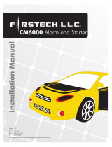
6-3. Key Switch Connector Wiring
(1) Remove the terminal of the
negative terminal of the battery.
(2) As shown in Fig. 3, disconnect
from the 3-pin connector of the
turbo timer body at a place about
5 cm (three thick lines).
(3) Connect the red line of the turbo
timer to the + B line as shown in Fig. 4.
・ If there are multiple + Bs, connect the red wire to one of them.
(4) Connect the green wire of the turbo timer to the IG wire as shown in Fig. 4.
If there are two IG wires, connect IG1 and IG2 using the green wire
cut out in (2).
Cut in about 5 cm
Turbo timer body
3 PIN
Fig. 3
Fig.4
Black:ground wire
Gray:Parking brake line
Red Green Blue
+B
IG1
IG2
ACC
Turbo timer body
Key cylinder
(5) Connect the blue wire of the turbo timer to the ACC wire as shown in
Fig. 4.
・If there is no ACC, the blue wire will not be used, so be sure to insulate
the blue wire with insulating tape.
(6) Connect the body ground (black) wire to a bolt etc. that can take the vehicle
body ground. (Peel off the paint and rust on the metal part that connects the
body ground wire with a file before connecting.)
6-5. Confirmation after wiring
(1) After wiring, check that the ground wire and power supply system
(+ B, ACC / IG1 / IG2) are correct.
Fig. 1
Key switch connector.
Look for a place that shows about 24V.
Connect to the place
where the body is
grounded.
The shape of the connector
and the number of wires vary
depending on the model.
(1) Strip 5mm of the wire cover for wiring as shown above.
(2) Connect another wire to the uncovered portion, and twist the wires
together.
(3) Stake the twisted wires using a splice.
(4) Cover the spliced wires with electrical tape to insulate.
Parking Brake
Switch
Fig. 2
Fig. 5
1
1
Main Unit
2
1
Parking Brake Wire
3
1
Double-sided Tape
4
1
Splice
5
3
Tie Wrap
(example) Part shape
No. Part name
Quantity
5
Tie Wrap
3
100mm
6
1
Instruction Manual
7
1
Gray 1.5m 60×30mm
Japanese English
Instruction Manual