
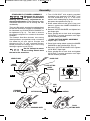
IMPORTANT: IMPORTANT : IMPORTANTE:
Read Before Using Lire avant usage Leer antes de usar
For English Version Version française Versión en español
See page 2 Voir page 22 Ver la página 42
Operating/Safety Instructions
Consignes de fonctionnement/sécurité
Instrucciones de funcionamiento y seguridad
1-800-4-DREMEL (1-800-437-3635) www.dremel.com
Call Toll Free for
Consumer Information
& Service Locations
Pour obtenir des informations
et les adresses de nos centres
de service après-vente,
appelez ce numéro gratuit
Llame gratis para
obtener información
para el consumidor y
ubicaciones de servicio
SM20
2610049812 09-07-2017.qxp_SM20 9/7/17 10:59 AM Page 1

-2-
Work area safety
Keep work area clean and well lit. Cluttered
or dark areas invite accidents.
Do not operate power tools in explosive
atmospheres, such as in the presence of
flammable liquids, gases or dust. Power
tools create sparks which may ignite the dust
or fumes.
Keep children and bystanders away while
operating a power tool. Distractions can
cause you to lose control.
Electrical safety
Power tool plugs must match the outlet.
Never modify the plug in any way. Do not
use any adapter plugs with earthed
(grounded) power tools. Unmodified plugs
and matching outlets will reduce risk of electric
shock.
Avoid body contact with earthed or grounded
surfaces such as pipes, radiators, ranges
and refrigerators. There is an increased risk
of electric shock if your body is earthed or
grounded.
Do not expose power tools to rain or wet
conditions. Water entering a power tool will
increase the risk of electric shock.
Do not abuse the cord. Never use the cord
for carrying, pulling or unplugging the power
tool. Keep cord away from heat, oil, sharp
edges or moving parts. Damaged or entangled
cords increase the risk of electric shock.
When operating a power tool outdoors,
use an extension cord suitable for outdoor
use. Use of a cord suitable for outdoor use
reduces the risk of electric shock.
If operating a power tool in a damp location
is unavoidable, use a Ground Fault Circuit
Interrupter (GFCI) protected supply. Use of
an GFCI reduces the risk of electric shock.
Personal safety
Stay alert, watch what you are doing and
use common sense when operating a
power tool. Do not use a power tool while
you are tired or under the influence of drugs,
alcohol or medication. A moment of inattention
while operating power tools may result in
serious personal injury.
Read all safety warnings and all instructions. Failure to follow the
warnings and instructions may result in electric shock, fire and/or serious
injury.
SAVE ALL WARNINGS AND INSTRUCTIONS FOR FUTURE REFERENCE
The term “power tool” in the warnings refers to your mains-operated (corded) power tool or
battery-operated (cordless) power tool.
General Power Tool Safety Warnings
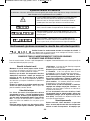
Safety Symbols
The definitions below describe the level of severity for each signal word. Please read the manual
and pay attention to these symbols.
!
This is the safety alert symbol. It is used to alert you to potential
personal injury hazards. Obey all safety messages that follow this
symbol to avoid possible injury or death.
DANGER indicates a hazardous situation which, if not avoided, will
result in death or serious injury.
WARNING indicates a hazardous situation which, if not avoided, could
result in death or serious injury.
CAUTION, used with the safety alert symbol, indicates a hazardous
situation which, if not avoided, will result in minor or moderate injury.
2610049812 09-07-2017.qxp_SM20 9/7/17 10:59 AM Page 2

Cut-Off Machine Safety Warnings
The guard provided with the tool must be
securely attached to the power tool and
positioned for maximum safety, so the least
amount of wheel is exposed towards the
operator. Position yourself and bystanders
away from the plane of the rotating wheel.
The guard helps to protect operator from
broken wheel fragments and accidental
contact with wheel.
Use only bonded reinforced or diamond
cut-off wheels for your power tool. Just
because an accessory can be attached to your
power tool, it does not assure safe operation.
The rated speed of the accessory must be
at least equal to the maximum speed
marked on the power tool. Accessories
running faster than their rated speed can break
and fly apart.
Wheels must be used only for
recommended applications. For example:
do not grind with the side of cut-off wheel.
Abrasive cut-off wheels are intended for
peripheral grinding, side forces applied to
these wheels may cause them to shatter.
Always use undamaged wheel flanges that
are of correct diameter for your selected
wheel. Proper wheel flanges support the
wheel thus reducing the possibility of wheel
breakage.
Do not use worn down wheels from larger
-3-
Use personal protective equipment. Always
wear eye protection. Protective equipment
such as dust mask, non-skid safety shoes, hard
hat, or hearing protection used for appropriate
conditions will reduce personal injuries.
Prevent unintentional starting. Ensure the
switch is in the off-position before
connecting to power source and / or battery
pack, picking up or carrying the tool.
Carrying power tools with your finger on the
switch or energizing power tools that have the
switch on invites accidents.
Remove any adjusting key or wrench before
turning the power tool on. A wrench or a
key left attached to a rotating part of the power
tool may result in personal injury.
Do not overreach. Keep proper footing and
balance at all times. This enables better
control of the power tool in unexpected
situations.
Dress properly. Do not wear loose clothing
or jewelry. Keep your hair, clothing and
gloves away from moving parts. Loose
clothes, jewelry or long hair can be caught in
moving parts.
If devices are provided for the connection
of dust extraction and collection facilities,
ensure these are connected and properly
used. Use of dust collection can reduce dust-
related hazards.
Power tool use and care
Do not force the power tool. Use the
correct power tool for your application. The
correct power tool will do the job better and
safer at the rate for which it was designed.
Do not use the power tool if the switch does
not turn it on and off. Any power tool that
cannot be controlled with the switch is
dangerous and must be repaired.
Disconnect the plug from the power source
and/or the battery pack from the power tool
before making any adjustments, changing
accessories, or storing power tools. Such
preventive safety measures reduce the risk of
starting the power tool accidentally.
Store idle power tools out of the reach of
children and do not allow persons unfamiliar
with the power tool or these instructions to
operate the power tool. Power tools are
dangerous in the hands of untrained users.
Maintain power tools. Check for misalignment
or binding of moving parts, breakage of
parts and any other condition that may
affect the power tool’s operation. If damaged,
have the power tool repaired before use.
Many accidents are caused by poorly
maintained power tools.
Keep cutting tools sharp and clean. Properly
maintained cutting tools with sharp cutting
edges are less likely to bind and are easier to
control.
Use the power tool, accessories and tool
bits etc. in accordance with these instructions,
taking into account the working conditions
and the work to be performed. Use of the
power tool for operations different from those
intended could result in a hazardous situation.
Service
Have your power tool serviced by a qualified
repair person using only identical
replacement parts. This will ensure that the
safety of the power tool is maintained.
2610049812 09-07-2017.qxp_SM20 9/7/17 10:59 AM Page 3

-4-
power tools. Wheel intended for larger power
tool is not suitable for the higher speed of a
smaller tool and may burst.
The outside diameter and the thickness of
your accessory must be within the capacity
rating of your power tool. Incorrectly sized
accessories cannot be adequately guarded or
controlled.
The arbor size of wheels and flanges must
properly fit the spindle of the power tool.
Wheels and flanges with arbor holes that do
not match the mounting hardware of the power
tool will run out of balance, vibrate excessively
and may cause loss of control.
Do not use damaged wheels. Before each
use, inspect the wheels for chips and
cracks. If power tool or wheel is dropped,
inspect for damage or install an
undamaged wheel. After inspecting and
installing the wheel, position yourself and
bystanders away from the plane of the
rotating wheel and run the power tool at
maximum no load speed for one minute.
Damaged wheels will normally break apart
during this test time.
Wear personal protective equipment.
Depending on application, use face shield,
safety goggles or safety glasses. As
appropriate, wear dust mask, hearing
protectors, gloves and shop apron capable
of stopping small abrasive or workpiece
fragments. The eye protection must be
capable of stopping flying debris generated by
various operations. The dust mask or
respirator must be capable of filtrating particles
generated by your operation. Prolonged
exposure to high intensity noise may cause
hearing loss.
Keep bystanders a safe distance away from
work area. Anyone entering the work area
must wear personal protective equipment.
Fragments of workpiece or of a broken wheel
may fly away and cause injury beyond
immediate area of operation.
Hold the power tool by insulated gripping
surfaces only, when performing an
operation where the cutting accessory may
contact hidden wiring or its own cord.
Cutting accessory contacting a “live” wire may
make exposed metal parts of the power tool
“live” and could give the operator an electric
shock.
Position the cord clear of the spinning
accessory. If you lose control, the cord may
be cut or snagged and your hand or arm may
be pulled into the spinning wheel.
Never lay the power tool down until the
accessory has come to a complete stop.
The spinning wheel may grab the surface and
pull the power tool out of your control.
Do not run the power tool while carrying it
at your side. Accidental contact with the
spinning accessory could snag your clothing,
pulling the accessory into your body.
Regularly clean the power tool’s air vents.
The motor’s fan will draw the dust inside the
housing and excessive accumulation of
powdered metal may cause electrical hazards.
Do not operate the power tool near
flammable materials. Sparks could ignite
these materials.
Do not use accessories that require liquid
coolants. Using water or other liquid coolants
may result in electrocution or shock.
Kickback and related warnings
Kickback is a sudden reaction to a pinched or
snagged rotating wheel. Pinching or snagging
causes rapid stalling of the rotating wheel
which in turn causes the uncontrolled power
tool to be forced in the direction opposite of the
wheel’s rotation at the point of the binding.
For example, if an abrasive wheel is snagged
or pinched by the workpiece, the edge of the
wheel that is entering into the pinch point can
dig into the surface of the material causing the
wheel to climb out or kick out. The wheel may
either jump toward or away from the operator,
depending on direction of the wheel’s
movement at the point of pinching. Abrasive
wheels may also break under these conditions.
Kickback is the result of power tool misuse
and/or incorrect operating procedures or
conditions and can be avoided by taking
proper precautions as given below.
Maintain a firm grip on the power tool and
position your body and arm to allow you to
resist kickback forces. Always use auxiliary
handle, if provided, for maximum control
over kickback or torque reaction during
start-up. The operator can control torque
reactions or kickback forces, if proper
precautions are taken.
Never place your hand near the rotating
accessory. Accessory may kickback over your
hand.
Do not position your body in line with the
rotating wheel. Kickback will propel the tool in
direction opposite to the wheel’s movement at
the point of snagging.
Use special care when working corners,
2610049812 09-07-2017.qxp_SM20 9/7/17 10:59 AM Page 4

GFCI and personal protection devices like
electrician’s rubber gloves and footwear will
further enhance your personal safety.
Do not use AC only rated tools with a DC
power supply. While the tool may appear to
work, the electrical components of the AC
rated tool are likely to fail and create a hazard
to the operator.
Keep handles dry, clean and free from oil
and grease. Slippery hands cannot safely
control the power tool.
Use clamps or another practical way to
secure and support the workpiece to a
stable platform. Holding the work by hand or
against your body leaves it unstable and may
lead to loss of control.
Develop a periodic maintenance schedule
for your tool. When cleaning a tool be
careful not to disassemble any portion of
the tool since internal wires may be
misplaced or pinched or safety guard return
springs may be improperly mounted.
Certain cleaning agents such as gasoline,
carbon tetrachloride, ammonia, etc. may
damage plastic parts.
Risk of injury to user. The power cord must only
be serviced by a Dremel Service Facility.
Do not use type 1A or 27A wheels for face
grinding. Side forces applied to these wheels
may cause them to shatter or burst.
Some dust created by
power sanding, sawing,
grinding, drilling, and other construction
activities contains chemicals known to
cause cancer, birth defects or other
reproductive harm. Some examples of
these chemicals are:
• Lead from lead-based paints,
• Crystalline silica from bricks and cement and
other masonry products, and
• Arsenic and chromium from chemically-
treated lumber.
Your risk from these exposures varies,
depending on how often you do this type of
work. To reduce your exposure to these
chemicals: work in a well ventilated area, and
work with approved safety equipment, such as
those dust masks that are specially designed
to filter out microscopic particles.
Do not cut solid metal
rod greater than 5/16".
Tool may become damaged.
Additional Safety Warnings
-5-
sharp edges etc. Avoid bouncing and
snagging the accessory. Corners, sharp
edges or bouncing have a tendency to snag
the rotating accessory and cause loss of
control or kickback.
Do not attach a saw chain, woodcarving
blade, segmented diamond wheel with a
peripheral gap greater than 10 mm or
toothed saw blade. Such blades create
frequent kickback and loss of control.
Do not “jam” the wheel or apply excessive
pressure. Do not attempt to make an
excessive depth of cut. Overstressing the
wheel increases the loading and susceptibility
to twisting or binding of the wheel in the cut
and the possibility of kickback or wheel
breakage.
When wheel is binding or when interrupting
a cut for any reason, switch off the power
tool and hold the power tool motionless
until the wheel comes to a complete stop.
Never attempt to remove the wheel from
the cut while the wheel is in motion
otherwise kickback may occur. Investigate
and take corrective action to eliminate the
cause of wheel binding.
Do not restart the cutting operation in the
workpiece. Let the wheel reach full speed
and carefully re-enter the cut. The wheel
may bind, walk up or kickback if the power tool
is restarted in the workpiece.
Support panels or any oversized workpiece
to minimize the risk of wheel pinching and
kickback. Large workpieces tend to sag under
their own weight. Supports must be placed
under the workpiece near the line of cut and
near the edge of the workpiece on both sides
of the wheel.
Use extra caution when making a “pocket
cut” into existing walls or other blind areas.
The protruding wheel may cut gas or water
pipes, electrical wiring or objects that can
cause kickback.
2610049812 09-07-2017.qxp_SM20 9/7/17 10:59 AM Page 5

-6-
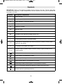
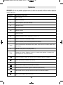
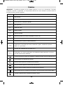
IMPORTANT: Some of the following symbols may be used on your tool. Please study them
and learn their meaning. Proper interpretation of these symbols will allow you to operate the
tool better and safer.
Symbols
Symbol Designation / Explanation
V Volts (voltage)
A Amperes (current)
Hz Hertz (frequency, cycles per second)
W Watt (power)
kg Kilograms (weight)
min Minutes (time)
s Seconds (time)
⌀Diameter (size of drill bits, grinding wheels, etc.)
n0No load speed (rotational speed at no load)
n Rated speed (maximum attainable speed)
.../min Revolutions or reciprocation per minute (revolutions, strokes, surface speed,
orbits etc. per minute)
0 Off position (zero speed, zero torque...)
1, 2, 3, ...
I, II, III,
Selector settings (speed, torque or position settings. Higher number means
greater speed)
0
Infinitely variable selector with off (speed is increasing from 0 setting)
Arrow (action in the direction of arrow)
Alternating current (type or a characteristic of current)
Direct current (type or a characteristic of current)
Alternating or direct current (type or a characteristic of current)
Class II construction (designates double insulated construction tools)
Earthing terminal (grounding terminal)
2610049812 09-07-2017.qxp_SM20 9/7/17 11:00 AM Page 6

-7-
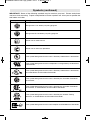
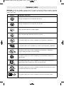
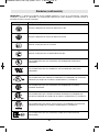
Symbols (continued)
IMPORTANT: Some of the following symbols may be used on your tool. Please study them
and learn their meaning. Proper interpretation of these symbols will allow you to operate the
tool better and safer.
Symbol Designation / Explanation
Designates Li-ion battery recycling program
Designates Ni-Cad battery recycling program
Alerts user to read manual
Alerts user to wear eye protection
This symbol designates that this tool is listed by Underwriters Laboratories.
This symbol designates that this component is recognized by Underwriters
Laboratories.
This symbol designates that this tool is listed by Underwriters Laboratories,
to United States and Canadian Standards.
This symbol designates that this tool is listed by the Canadian Standards
Association.
This symbol designates that this tool is listed by the Canadian Standards
Association, to United States and Canadian Standards.
This symbol designates that this tool is listed by the Intertek Testing
Services, to United States and Canadian Standards.
This symbol designates that this tool complies to NOM Mexican Standards.
2610049812 09-07-2017.qxp_SM20 9/7/17 11:00 AM Page 7

-8-
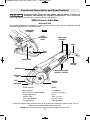
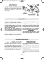
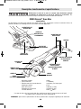
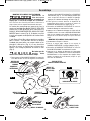
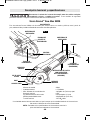
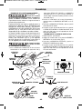
Functional Description and Specifications
Disconnect the plug from the power source before making any
assembly, adjustments or changing accessories. Such preventive
safety measures reduce the risk of starting the tool accidentally.
SM20 Dremel®Saw-Max
Model number SM20
* Rated speed n 17,000/min
* Max. abrasive wheel diameter 3" (76.2 mm) type 1
Amperage rating 6.0 A
Wheel arbor .433" (11 mm)
Max. cutting depth 3/4" (21.5 mm)
Voltage rating 120V 60Hz
FIG. 1
* Accessory speed rating must be equal to or greater than the tool’s speed rating. Do not
exceed the recommended wheel diameter.
NOTE: For tool specifications refer to the nameplate on your tool.
SPINDLE LOCK
FOOT
VENTILATION
OPENINGS
ABRASIVE
WHEEL
VENTILATION
OPENINGS
PADDLE SWITCH WITH
"LOCK-OFF" FEATURE
CORD
"LOCK-ON"
BUTTON
DEPTH SCALE
DEPTH
ADJUSTMENT
LEVER
DUST
PORT
FLUSH CUT
FOOT
LINE GUIDE
INTENDED USE
This Dremel SM20 tool is intended for cuts in wood, plastic, metal, drywall, fiberboard and tile
using the applicable Saw-Max accessories.
2610049812 09-07-2017.qxp_SM20 9/7/17 11:00 AM Page 8

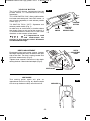
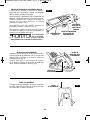
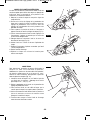
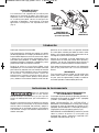
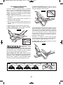
STANDARD FLAT WHEEL ASSEMBLY
Disconnect the plug from
the power source before
making any assembly, adjustments or
changing accessories. Such preventive safety
measures reduce the risk of starting the tool
accidentally.
The Lock Bolt which attaches the cutting wheel
to the tool should be turned CLOCKWISE to
be loosened and COUNTERCLOCKWISE to
be tightened (Fig. 3). This bolt is reverse
threaded compared to standard threaded
fasteners.
The Dremel Saw-Max features two cutting
wheel positions- one position using a standard
flat wheel for all your typical straight and
plunge cuts (Fig. 4), and a second optional
wheel position for making flush cuts along
flooring or against a wall (Fig. 5).
Do not attempt to mount
two cutting wheels onto
the tool at the same time.
1. Turn LOCK BOLT with wrench provided
clockwise and remove LOCK BOLT and
OUTER WASHER (Fig. 2). If the shaft
moves while attempting to loosen the lock
bolt press the spindle lock (Fig. 2).
2. Slide wheel behind the guard face and
mount it against the INNER WASHER on
the shaft (Fig. 4).
3. Reinstall OUTER WASHER and tighten lock
bolt finger tight.
4. Press spindle lock to lock shaft and tighten
LOCK BOLT counter-clockwise until tight
with the wrench provided.
FLUSH CUTTING WHEEL ASSEMBLY
1. Repeat step 1 of above.
2. Place flush cutting wheel against the INNER
WASHER on the spindle shaft. (Fig. 5).
3. Reinstall OUTER WASHER and tighten
LOCK BOLT finger tight.
4. Press spindle lock to lock shaft and tighten
LOCK BOLT counter-clockwise until tight
with the wrench provided.
Assembly
SPINDLE LOCK
GUARD
FACE
FIG. 4 FIG. 5
INNER
WASHER
OUTER WASHER
LOCK
BOLT
FLUSH CUTTING
WHEEL
(OPTIONAL)
STANDARD
FLAT WHEEL
GUARD FACE
STANDARD WHEEL
-9-
WRENCH
FLUSH
CUTTING WHEEL
FIG. 2
FIG. 3
LOOSEN TIGHTEN
LOCK BOLT
2610049812 09-07-2017.qxp_SM20 9/7/17 11:00 AM Page 9

-10-
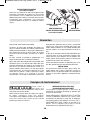
Introduction
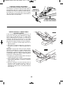
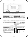
DUST EXTRACTION
(Optional accessory)
Your tool is equipped with a dust port for dust
extraction. To use this feature, insert dust
port adapter into dust port, attach vacuum
hose into the adapter, then connect the
opposite end of the hose to a shop vacuum
cleaner (Fig. 6).
DUST PORT ADAPTER
(Optional accessory)
VACUUM
HOSE
(Not included)
DUST
PORT
FIG. 6
Thank you for purchasing the Dremel SM20.
This tool was designed to tackle a wide variety
of projects in and around the home. The
Dremel SM20 completes tasks quicker and
more efficiently than a series of other tools that
would be needed to complete a job or project.
This tool is also compact, ergonomic, and cuts
virtually all common materials.
After using your new Dremel SM20 you’ll find
that it is the right size tool to get projects done
at just a fraction of the size of a traditional
circular saw. With a full line of accessories the
tool cuts through virtually any common material
in the home- wood, plastic, metal, drywall and
tile. The tool also features two cutting wheel
positions, one position using a standard flat
wheel for all your typical straight cuts and a
second position for making flush cuts along
flooring or against a wall.
In addition to versatility, the Dremel SM20
provides excellent line of sight for confident,
precise cuts so you will get accurate cuts the
first attempt and avoid wasting time or material.
Visit www.dremel.com to learn more about
what you can do with your new Dremel tool.
INTENDED USE
This Dremel SM20 tool is intended for straight
cuts in wood, plastic, metal, drywall, fiberboard,
and tile using the applicable accessories
recommended by Dremel.
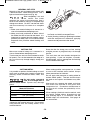
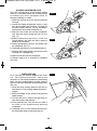
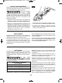
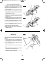
Operating Instructions
Hold the tool with both
hands while starting the
tool, since torque from the motor can cause the
tool to twist.
Start the tool before applying to work and let
the tool come to full speed before contacting
the workpiece. Lift the tool from the work
before releasing the switch. DO NOT turn the
switch “ON” and “OFF” while the tool is under
load; this will greatly decrease the switch life.
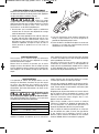
PADDLE SWITCH WITH
"LOCK-OFF" FEATURE
The Paddle switch enables the operator to
control the switch functions of "Lock-OFF",
and "ON/OFF".
TO UNLOCK SWITCH AND TURN TOOL
"ON": Push "Lock-OFF" switch release lever
forward to unlock paddle switch, then squeeze
paddle switch (Fig. 7).
TO SWITCH TOOL "OFF": Release pressure
on paddle lever. The switch is spring loaded
and will return to "OFF" position automatically
(Fig. 7).
2610049812 09-07-2017.qxp_SM20 9/7/17 11:00 AM Page 10

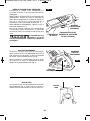
DEPTH ADJUSTMENT
Disconnect plug from power source. Loosen
the depth adjustment lever located on the right
side of the tool. The foot is spring loaded and
will lower automatically (Fig. 8).
Tighten lever counter clockwise at the depth
setting desired. Check desired depth (Fig. 8).
DEPTH SCALE
DEPTH
ADJUSTMENT
LEVER
FIG. 8
-11-
LINE GUIDE
The cutting guide notch will give an
approximate line of cut (Fig. 9). Make sample
cuts in scrap lumber to verify actual line of cut. LINE GUIDE
FIG. 9
"LOCK-ON" BUTTON
The "Lock-ON" feature, incorporated into the
paddle switch, is a convenience for long
operations.
TO LOCK SWITCH "ON": After paddle switch
has been activated push "Lock-ON" button at
rear of tool completely in and release paddle
switch (Fig. 7).
TO SWITCH TOOL "OFF": Squeeze and
release paddle switch (Fig. 7).
In order to try to avoid recoil (a situation where
the wheel wants to skip out of the material) it
is recommended to make cuts in the same
direction as the rotation of the wheel.
It is important to read
and understand the
section in this manual called “Kickback
and Related Warnings”.
FIG. 7
PADDLE
SWITCH
"LOCK-ON"
BUTTON
"LOCK-OFF"
SWITCH
RELEASE LEVER
2610049812 09-07-2017.qxp_SM20 9/7/17 11:00 AM Page 11

GENERAL CUT OFFS
Maintain a firm grip and operate the switch with
a decisive action. Never force the tool. Use a
light and continuous pressure (Fig. 10).
After completing a cut and
the switch has been
released, be aware of the necessary time it
takes for the wheel to come to a complete stop
during coast down. Do NOT set the tool down
until the accessory has come to a complete
stop.
1. Make sure material being cut is secured in a
vise or fixture before attempting to cut
2. Keep your body positioned to either side of
the wheel, but not in line with the wheel. It is
important to support the tool properly and to
position your body such as to minimize body
exposure from possible wheel binding and
recoil.
3. Grip the tool firmly while cutting and always
be ready and able to manage the cut.
4. Avoid jamming, twisting or pinching the wheel
with the workpiece of otherwise applying
excessive side pressure to the wheel.
-12-
CUTTING METAL
It is possible to perform limited cutting on small
stock such as copper pipe, conduit, coated wire
shelving, HVAC, aluminum sheet, cutter, and
fascia.
Do not make repeated
cuts, or cut longer then 2
feet in sheet metal. Sparks may damage
guard.
When cutting, work with moderate feed,
adapted to the material being cut. Do not exert
side pressure onto the cutting wheel, tilt or
oscillate the tool.
When cutting profiles and square bar, it is best
to start at the smallest cross section. Always
follow precautions for kickback.
Do not apply side pressure to cutting wheel to
reduce wheel speed. The tool should always
be used so that sparks are directed away from
user.
After each use, remove the wheel and clean
the inside and outside of the guard with
compressed air. Preventive maintenance of
the guard will reduce the probability of an
accident.
When cutting cylindrical metal materials such
as conduit, copper tubing, threaded rod and
wire shelving up to ½” in diameter, use the
SM846 chop saw attachment. See page 16
for instructions.
Recommended Maximum
Material Thicknes
sThreaded Rod 5/16" (7.9 mm)
Sheet Metal 1/32" (20 Gauge) (.91 mm)
Conduit 1/2" (12.7 mm)
Masonry Score and then break
FIG. 10
CUTTING TILE
Make sure material being cut is secured in a
vise or fixture before attempting to cut.
Turn the tool on and wait for the wheel to reach
full speed. For cuts that extend to the edge of a
tile, cut all the way through edge(s) along your
cut line.
Score the tile first along your cut line, making
multiple passes to progressively cut through
the tile.
This tool does not use wheels designed for
face-grinding. If your cut requires a smooth,
finished edge, use an appropriate tile finishing
tool to refine the tile edge.
2610049812 09-07-2017.qxp_SM20 9/7/17 11:00 AM Page 12

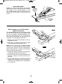
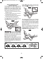
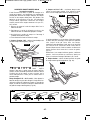
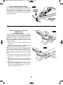
PLUNGE OR INTERIOR CUTS
The size and versatility of the Dremel SM20
make it an excellent option for making plunge
or interior cuts into a workpiece such as
flooring, paneling, or siding.
1. Mark the surface to be cut with the desired
cut lines
2. Loosen the Depth Adjustment Lever so that
the spring loaded foot releases and goes to
the zero depth setting. Leave the Depth
Adjustment Lever loose during this cut.
3. Rest the Foot of the tool on the workpieces
and Align the tool’s wheel with the cut line
(Fig. 11).
4. While holding the tool firmly, Press the
Paddle Switch and allow the tool’s wheel to
come up to full speed.
5. Slowly plunge/lower the tool and wheel into
the workpiece (Fig. 12).
6. Guide the tool forward and complete the cut
7. Release the Paddle Switch and allow the tool
to come to a complete stop.
8. Remove the tool from the workpiece.
9. Repeat steps 3-8 as required to complete
your cuts.
-13-
FIG. 11
FIG. 12
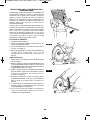
FLUSH CUTTING
First, consider the desired height of the flush
cut. For flooring installation, add up the
thickness of your flooring adhesive, the flooring
itself, and any underlayments or other material
that will add to the thickness of the finished floor
(Fig. 13).
1. Install the flush cutting wheel on the tool as
described in “Flush Cutting Wheel Assembly”,
page 9.
2. Adjust the depth of the wheel to the desired
depth setting.
3. Turn the tool on it’s side so that the flush cut
foot rests against the flooring.
4. Firmly grip the tool. Turn tool on and allow it
to come to full speed before entering
workpiece.
5. Complete your cut and remove the tool from
the workpiece before turning the tool off.
FIG. 13
2610049812 09-07-2017.qxp_SM20 9/7/17 11:00 AM Page 13

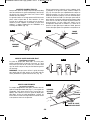
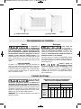
RIP CUTS
(Optional attachment)
Rip cuts are easy to do with a straight edge
guide (Fig. 17). Straight edge guide is available
as an accessory. To attach, insert straight edge
guide, insert fence through slots in foot to
desired width as shown and secure with the set
screw.
FIG. 17
SET
SCREW
DESIRED
WIDTH OF
CUT
STRAIGHT
EDGE GUIDE
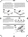
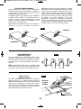
CUTTING LARGE SHEETS
When making cuts longer than 2 feet in material
such as plywood, tool may become hot. To
avoid this, let the tool rest in between cutting.
Large sheets and long boards sag or bend,
depending on support. If you attempt to cut
without leveling and properly supporting the
piece, the wheel will tend to bind, causing KICK-
BACK and extra load on the motor (Fig. 14).
Support the panel or board close to the cut, as
shown in (Fig. 15). Be sure to set the depth of
the cut so that you cut through the sheet or
board only and not the table or work bench. The
two-by-fours used to raise and support the work
should be positioned so that the broadest sides
support the work and rest on the table or bench.
Do not support the work with the narrow sides
as this is an unsteady arrangement. If the sheet
or board to be cut is too large for a table or work
bench, use the supporting two-by-fours on the
floor and secure.
-14-
EDGE GUIDE
(Optional attachment)
The straight edge guide is used for cuts
parallel to the edge of the work, and can be
used from either side of the foot plate for
cutting on the left or right side of the material.
NOTE: When using the straight edge guide on
the left side or right side of the tool, position
guide as shown (Fig. 16).
FIG. 14 FIG. 15
WRONG
RIGHT
FIG. 16
2610049812 09-07-2017.qxp_SM20 9/7/17 11:00 AM Page 14

-15-
RIP BOARD GUIDE
When rip cutting large sheets, the straight
edge guide may not allow the desired width of
cut. Clamp or nail a straight piece of 1" (25
mm) lumber to the sheet as a guide (Fig. 18).
Use the left side of the foot against the board
guide.
DESIRED
WIDTH OF
CUT
RIP BOARD
GUIDE
FIG. 18
MODEL SM842 2 X 4 CUTTING GUIDE
(Optional Accessory)
The Dremel SM20 and the 2x4 Cutting Guide
can be used to quickly and accurately make
cuts in 2 x 4 lumber. Since the depth of cut is
less than the thickness of a 2 x 4 one cut on
each side of the wood will be required to
complete a cut through the work piece.
1. Measure and mark the desired cut line on
the piece of wood.
2. Slide the 2 x 4 Cutting Guide over the wood
in the designated location of the cut.
Note: When using the standard wheel
measure a 1” offset to properly align the guide
to the offset indicator in the cutting guide.
While using the flush cut wheel, line the fence
of the tool up with the cut line.
3. Clamp the cutting guide to the work piece in
the desired location to make the cut.
4. Firmly hold the tool and use the edge of the
guide as a fence and make the first cut,
(Fig. 19)
5. Flip the work piece over while leaving the
cutting guide clamped in place and make a
second cut to complete the cut through the
2 x 4, (Fig. 20)
FIG. 19
FIG. 20
2610049812 09-07-2017.qxp_SM20 9/7/17 11:00 AM Page 15

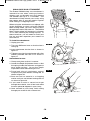
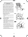
SM846 CHOP SAW ATTACHMENT
The Dremel SM846 chop saw attachment is
intended for use when cutting cylindrical
objects such as threaded rod, wire shelving
and wooden rods up to ½” in diameter. This
attachment will help control your cut by using
the support tabs to rest the material against
while cutting in a chopping motion.
When using the attachment to cut objects with
larger diameters or when using the SM510
Metal Cutting wheel, you won’t always make it
through the material with one cut. The SM510
Metal Cutting wheel will decrease in diameter
as it’s used, reducing the cutting capacity. In
these instances, you will need to make your
first cut and then reposition your material to
finish the cut.
To install the attachment:
1. Unplug your tool.
2. Turn your SM20 tool over so that the foot is
facing up.
3. Insert attachment into the foot as shown in
figure 21.
4. Tighten screw into the attachment with allen
wrench provided with tool kit as shown in
figure 21.
Instructions for use:
1. Clamp work piece so that it is secure.
2. Loosen the Depth Adjustment Lever so that
the spring loaded foot releases and goes to
zero depth setting. Leave the Depth
Adjustment Lever loose during this cut.
3. Place both tabs of attachment against
clamped work piece before starting tool as
shown in figure 22.
4. Start tool and cut material in a chopping
motion until you are finished making the cut
as shown in figure 23.
5. If you need to make a second cut to get
through the material, turn off tool and rotate
the work piece 90 degrees in your clamp.
6. Once secured in your clamp, finish cutting
through your material with a second cut.
-16-
FIG. 21
FIG. 22
FIG. 23
2610049812 09-07-2017.qxp_SM20 9/7/17 11:00 AM Page 16

-17-
MODEL SM840 MITER GUIDE
(Optional Attachment)
The Dremel Saw-Max, Miter Guide and Flush
Cutting Wheel is a perfect combination to
make miter, bevel, and straight cuts in
baseboard, trim, and molding, (Fig. 28). Angle
indicators also aid in making accurate cuts for
other common angles like 15°, 22.5° or 30°.
1. Measure and mark the desired cut line on
the piece of wood.
2. Position the Miter Guide over the wood in
the designated location of the cut.
3. Clamp the cutting guide to the workpiece in
the desired location to make the cut.
4. Firmly hold the tool and make the cut.
1. 45° Miter Cuts- use the angled edge of the
cutting guide as the fence, (Fig. 24).
Ensure the tool is properly
seated in the guide before
starting the tool and use caution when
stopping the tool within the cutting rail to
ensure that the cutting wheel does not come
into contact with the cutting guide.
Miter Cuts (15°, 22.5° or 30°)- Pivot the
cutting guide at the designated corner to the
desired angle using the angle indicator
marking on the cutting guide, complete the cut
using the outside edge of the cutting guide as
the fence, (Fig. 24).
2. 45° Bevel Cuts- While using the flush
cutting wheel only, place the saw in the cutting
rail to complete the cut, (Fig. 25).
The guide positions the saw to make bevel
cuts in workpieces up to 9/16" thick. To make
a cut, first position the tool into the rail so the
back of the tool’s foot fits into the keying
feature. Switch on the tool and proceed to
make the cut. Stop the tool before removing
from guide, (Fig. 27).
Determine if a Inside Left, Outside Left, Inside
Right, or Outside Right cut is required and
orient the workpiece. Positions A, B, C, or D.
3. Straight Cuts- use the outside edge of the
cutting guide as the fence, (Fig. 26)
FIG. 24
FIG. 26
FIG. 25
FIG. 27
2610049812 09-07-2017.qxp_SM20 9/7/17 11:00 AM Page 17

-18-
Extension Cords
Service
NO USER SERVICE -
ABLE PARTS INSIDE.
Preventive maintenance performed by un -
au thorized personnel may result in
misplacing of internal wires and
components which could cause serious
hazard. We recommend that all tool service
be performed by a Dremel Service Facility.
CARBON BRUSHES
The brushes and commutator in your tool have
been engineered for many hours of dependable
service. To maintain peak efficiency of the
motor, we recommend that the brush es be
serviced by a Dremel Service Facility.
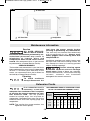
Cleaning
To avoid accidents
always dis connect the
tool from the power supply before
cleaning or performing any main tenance.
The tool may be cleaned most effectively
with compressed dry air. Always wear
safety gog gles when cleaning tools with
compressed air.
Ventilation openings and switch levers must
be kept clean and free of foreign matter. Do
not at tempt to clean by inserting pointed
objects through openings.
Certain cleaning agents
and sol vents damage
plastic parts. Some of these are: gasoline,
carbon tetrachlo ride, chlo rinated cleaning
solvents, ammonia and house hold
detergents that contain ammonia.
Maintenance Information
FIG. 28
45° Miter Cuts
45° Bevel Cuts Straight Cuts
If an extension cord is
necessary, a cord with
adequate size conductors that is capable
of carrying the current necessary for your
tool must be used. This will prevent
excessive voltage drop, loss of power or
overheating. Grounded tools must use 3-wire
extension cords that have 3-prong plugs and
receptacles.
NOTE: The smaller the gauge number, the
higher the cord capacity.
RECOMMENDED SIZES OF EXTENSION CORDS
120 VOLT ALTERNATING CURRENT TOOLS
Tool’s
Ampere
Rating
Cord Size in A.W.G. Wire Sizes in mm2
Cord Length in Feet Cord Length in Meters
25 50 100 150 15 30 60 120
3-6
6-8
8-10
10-12
12-16
18
18
18
16
14
16
16
16
16
12
16
14
14
14
–
14
12
12
12
–
0.75
0.75
0.75
1.0
–
0.75
1.0
1.0
2.5
–
1.5
2.5
2.5
4.0
–
2.5
4.0
4.0
–
–
2610049812 09-07-2017.qxp_SM20 9/7/17 11:00 AM Page 18

-19-
Wood & Plastic Carbide Wheel
SM500
Abrasive cutting wheel with carbide grit
which is intended to cut wood and other soft
materials.
Metal Cut-off Wheel
SM510
Reinforced Type 1 Abrasive cut-off
wheel which is intended to cut a variety of
materials such as metal and plastic.
Masonry Cut-off Wheel
SM520
Reinforced Type 1 Abrasive cut-off
wheel which is intended to make sore cuts in
masonry and stone.
Diamond Wheel
SM540
Diamond abrasive wheel which is
intended to make cuts in hard materials such
as marble, concrete, brick, porcelain, and tile.
Wood & Plastic Flush Cut
Carbide Wheel
SM600
Offset abrasive cutting wheel with carbide grit
which is intended to cut wood and other soft
materials.
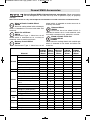
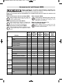
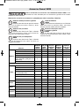
Dremel SM20 Accessories
Use only Dremel SM20, high-performance accessories. Other accessories
are not designed for this tool and may lead to personal injury or property
damage.
Store accessories in a dry and temperate environment to avoid corrosion and deterioration.
Material
SM500
Carbide
Wheel
SM510
Metal
Cut-off
Wheel
SM520
Masonry
Cut-off
Wheel
SM540
Diamond
Wheel
SM600
Flush Cut
Wheel
Wood
Plywood X X
Pine X X
Poplar X X
Oak X X
Composite (OSB, fiberboard) X X
Laminate flooring X X
Drywall Drywall X X
Metal
Copper Pipe X
Conduit X
Coated Wire shelving X
HVAC X
Aluminum sheet, gutter,
fascia X
Galvanized sheet metal X
Threaded rod X
Plastic
Plexiglass (sheet plastic) X X X
Vinyl siding, gutter X X X
PVC pipe X X X
Tile Wall Tile X
Floor Tile X
Masonry
Brick Fascia X X
Cement board X X
Pavers X
Other Fiberglass X X
2610049812 09-07-2017.qxp_SM20 9/7/17 11:00 AM Page 19

-20-
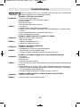
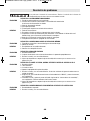
Trouble Shooting
Read instruction manual first! Remove plug from the power source before
making adjustments or assembling the wheel.
TROUBLE: TOOL WILL NOT START
PROBLEM 1. Power cord is not plugged in.
2. Power source fuse or circuit breaker tripped.
3. Cord damaged.
4. Burned out switch.
5. Paddle switch does not turn tool on.
REMEDY 1. Plug tool in.
2. Replace fuse or reset tripped circuit breaker.
3. Inspect cord for damage. If damaged, have cord replaced by a Dremel Service
Facility.
4. Have switch replaced by a Dremel Service Facility.
5. Lock-Off feature not activated.
TROUBLE: WHEEL DOES NOT COME UP TO SPEED
PROBLEM 1. Extension cord too light or too long.
2. Low house voltage.
REMEDY 1. Replace with adequate cord.
2. Contact your electric company.
TROUBLE: EXCESSIVE VIBRATION
PROBLEM 1. Wheel out of balance.
2. Workpiece not clamped or supported properly.
REMEDY 1. Discard wheel and use different wheel.
2. Clamp or support workpiece as shown on pages 13 and 14.
TROUBLE: CUT BINDS, BURNS, STALLS MOTOR WHEN RIPPING
PROBLEM 1. Dull wheel.
2. Warped board.
3. Wheel binds.
4. Improper workpiece support.
REMEDY 1. Discard wheel and use a different wheel. Or clean debris from carbide grit with a
wire brush.
2. Make sure concave or hollow side is facing “DOWN” feed slowly, see page 13.
3. Assemble wheel and tighten Lock Bolt per “Assembly Instructions”, see page 9.
Or only attempt to make straight cuts.
4. Clamp or support workpiece as shown on pages 13 and 14.
TROUBLE: WHEEL MARKS FLOORING WHILE FLUSH CUTTING
PROBLEM 1. Bent or warped wheel.
REMEDY 1. Discard wheel and use different wheel.
2610049812 09-07-2017.qxp_SM20 9/7/17 11:00 AM Page 20
Page is loading ...
Page is loading ...
Page is loading ...
Page is loading ...
Page is loading ...
Page is loading ...
Page is loading ...
Page is loading ...
Page is loading ...
Page is loading ...
Page is loading ...
Page is loading ...
Page is loading ...
Page is loading ...
Page is loading ...
Page is loading ...
Page is loading ...
Page is loading ...
Page is loading ...
Page is loading ...
Page is loading ...
Page is loading ...
Page is loading ...
Page is loading ...
Page is loading ...
Page is loading ...
Page is loading ...
Page is loading ...
Page is loading ...
Page is loading ...
Page is loading ...
Page is loading ...
Page is loading ...
Page is loading ...
Page is loading ...
Page is loading ...
Page is loading ...
Page is loading ...
Page is loading ...
Page is loading ...
Page is loading ...
Page is loading ...
Page is loading ...
Page is loading ...
-
 1
1
-
 2
2
-
 3
3
-
 4
4
-
 5
5
-
 6
6
-
 7
7
-
 8
8
-
 9
9
-
 10
10
-
 11
11
-
 12
12
-
 13
13
-
 14
14
-
 15
15
-
 16
16
-
 17
17
-
 18
18
-
 19
19
-
 20
20
-
 21
21
-
 22
22
-
 23
23
-
 24
24
-
 25
25
-
 26
26
-
 27
27
-
 28
28
-
 29
29
-
 30
30
-
 31
31
-
 32
32
-
 33
33
-
 34
34
-
 35
35
-
 36
36
-
 37
37
-
 38
38
-
 39
39
-
 40
40
-
 41
41
-
 42
42
-
 43
43
-
 44
44
-
 45
45
-
 46
46
-
 47
47
-
 48
48
-
 49
49
-
 50
50
-
 51
51
-
 52
52
-
 53
53
-
 54
54
-
 55
55
-
 56
56
-
 57
57
-
 58
58
-
 59
59
-
 60
60
-
 61
61
-
 62
62
-
 63
63
-
 64
64


Ask a question and I''ll find the answer in the document
Finding information in a document is now easier with AI
in other languages
- français: Dremel SM20 Manuel utilisateur
- español: Dremel SM20 Manual de usuario
Related papers
Other documents
-
Bosch GWS10-45P Operating/Safety Instructions Manual
-
Bosch CAG180BN User guide
-
 RotoZip SS560VSC-31 User guide
-
Worx WX996L Owner's manual
-
Kobalt KMC 124B-03 User manual
-
MasterForce V User manual
-
Bosch Power Tools 1821D User manual
-
Bosch Power Tools 1811PS User manual
-
Bosch Power Tools DGSH181K User manual
-
Bosch GWS13-50VS Owner's manual
