6
ss
ss
sCleaning the filters
•Clean the filters using a vacuum cleaner. If you do not have a vacuum
cleaner, tap the filters against a solid object to knock off dirt and dust.
•If the filters are especially dirty, wash them in lukewarm water. Take care
to rinse off any detergent thoroughly and allow the filters to dry com-
pletely before putting them back into the unit.
Caution:
• Do not dry the filters in direct sunlight or by using a heat source,
such as an electric heater: this may warp them.
• Do not wash the filters in hot water (above 50°C), as this may warp
them.
• Make sure that the air filters are always installed. Operating the
unit without air filters can cause malfunction.
Caution:
• Before you start cleaning, stop operation and turn OFF the power
supply.
• Indoor units are equipped with filters to remove the dust of sucked-in
air. Clean the filters using the methods shown in the following sketches.
6. Care and Cleaning
ss
ss
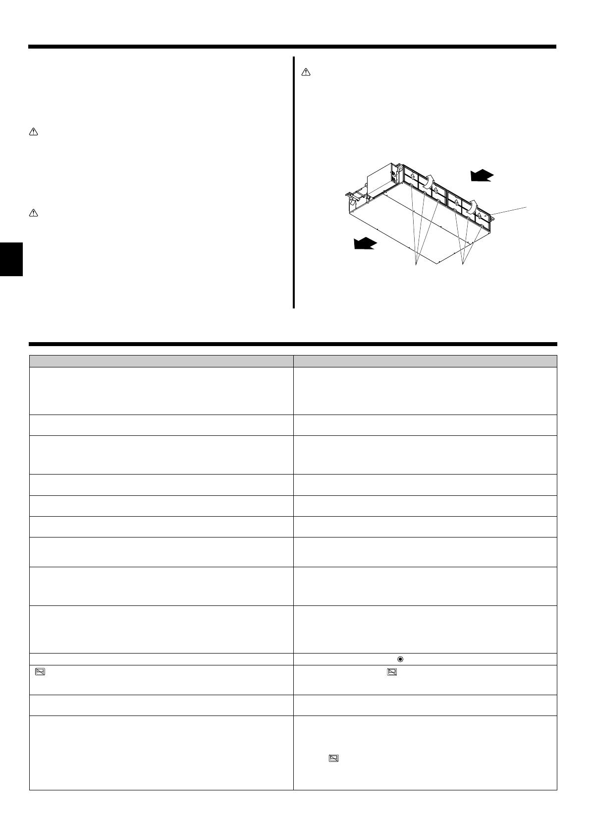
sFilter removal
Caution:
• In removing the filter, precautions must be taken to protect your
eyes from dust. Also, if you have to climb up on a stool to do the
job, be careful not to fall.
• When the filter is removed, do not touch the metallic parts inside
the indoor unit, otherwise injury may result.
■SEZ-KD·VAL
B
C
A
D
D
• While lifting the filter knob, pull it.
AAir intake BAir outlet C Filter D Knob
7. Trouble Shooting
Having trouble?
Air conditioner does not heat or cool well.
When heating operation starts, warm air does not blow from the indoor unit
soon.
During heating mode, the air conditioner stops before the set room tem-
perature is reached.
When the airflow direction is changed, the vanes always move up and down
past the set position before finally stopping at the position.
A flowing water sound or occasional hissing sound is heard.
A cracking or creaking sound is heard.
The room has an unpleasant odor.
A white mist or vapor is emitted from the indoor unit.
Water or vapor is emitted from the outdoor unit.
The operation indicator does not appear in the remote controller display.
“ ” appears in the remote controller display.
When restarting the air conditioner soon after stopping it, it does not oper-
ate even though the ON/OFF button is pressed.
Air conditioner operates without the ON/OFF button being pressed.
Here is the solution. (Unit is operating normally.)
■Clean the filter. (Airflow is reduced when the filter is dirty or clogged.)
■Check the temperature adjustment and adjust the set temperature.
■Make sure that there is plenty of space around the outdoor unit. Is the
indoor unit air intake or outlet blocked?
■Has a door or window been left open?
■Warm air does not blow until the indoor unit has sufficiently warmed up.
■When the outdoor temperature is low and the humidity is high, frost may
form on the outdoor unit. If this occurs, the outdoor unit performs a de-
frosting operation. Normal operation should begin after approximately
10 minutes.
■When the airflow direction is changed, the vanes move to the set position
after detecting the base position.
■These sounds can be heard when refrigerant is flowing in the air condi-
tioner or when the refrigerant flow is changing.
■These sounds can be heard when parts rub against each due to expan-
sion and contraction from temperature changes.
■The indoor unit draws in air that contains gases produced from the walls,
carpeting, and furniture as well as odors trapped in clothing, and then
blows this air back into the room.
■If the indoor temperature and the humidity are high, this condition may
occur when operation starts.
■During defrosting mode, cool airflow may blow down and appear like a
mist.
■During cooling mode, water may form and drip from the cool pipes and
joints.
■During heating mode, water may form and drip from the heat exchanger.
■During defrosting mode, water on the heat exchanger evaporates and
water vapor may be emitted.
■
Turn on the power switch. “ ” will appear in the remote controller display.
■During central control, “ ” appears in the remote controller display and
air conditioner operation cannot be started or stopped using the remote
controller.
■Wait approximately three minutes.
(Operation has stopped to protect the air conditioner.)
■Is the on timer set?
Press the ON/OFF button to stop operation.
■Is the air conditioner connected to a central remote controller?
Consult the concerned people who control the air conditioner.
■Does “ ” appear in the remote controller display?
Consult the concerned people who control the air conditioner.
■Has the auto recovery feature from power failures been set?
Press the ON/OFF button to stop operation.
KB79H174H01_en.pm6 07.7.11, 9:14 AM6


