Page is loading ...

Storatherm Aqua Compact 20.01.2015 Rev.1
With heat exchanger: AC 60/1-W, AC 110/1-W, AC 160/1-W
With electric heating element: AC 60/E-W, AC 100/1-W, AC 160/1-W
With electric heating element and heat exchanger: AC 60/1E-W, AC
110/1E-W, AC 160/1E-W
GB
Operating manual
Original operating manual


Contents
Storatherm Aqua Compact — 20.01.2015 Rev.1 English —
3
English
Storath er m Aq u a C om pac t
20.01.2015 Rev.1
Contents
1
Notes on the operating manual..................................................................................................................................................... 5
2
Liability and guarantee................................................................................................................................................................... 5
3
Safety................................................................................................................................................................................................ 6
3.1 Explanation of symbols ........................................................................................................................................................................ 6
3.1.1 Symbols and notes used ................................................................................................................................................... 6
3.1.2 Safety symbols used .......................................................................................................................................................... 6
3.2 Personnel requirements ...................................................................................................................................................................... 7
3.3 Personal protective equipment .......................................................................................................................................................... 7
3.4 Intended use .......................................................................................................................................................................................... 7
3.5 Inadmissible operating conditions..................................................................................................................................................... 7
3.6 Residual risks ......................................................................................................................................................................................... 8
4
Description of the device................................................................................................................................................................ 9
4.1 Regulations ............................................................................................................................................................................................ 9
4.2 Transportation ....................................................................................................................................................................................... 9
4.3 Corrosion protection ............................................................................................................................................................................ 9
4.4 Design and connection dimensions ................................................................................................................................................. 10
4.5 Identification ....................................................................................................................................................................................... 11
4.5.1 Nameplate ........................................................................................................................................................................ 11
4.5.2 Type code .......................................................................................................................................................................... 11
5
Technical data ............................................................................................................................................................................... 12
6
Installation ..................................................................................................................................................................................... 13
6.1 Installation conditions ....................................................................................................................................................................... 13
6.1.1 Installation location ........................................................................................................................................................ 13
6.1.2 Installation ........................................................................................................................................................................ 13
6.1.3 Connection on "heating water" side ............................................................................................................................ 13
6.1.4 Connection on "water" side ........................................................................................................................................... 14
6.2 Preparatory work ................................................................................................................................................................................ 14
6.3 Execution .............................................................................................................................................................................................. 14
6.3.1 Hydraulic connection ...................................................................................................................................................... 15
6.3.2 Drinking-water expansion vessel .................................................................................................................................. 16
6.4 Electrical connection .......................................................................................................................................................................... 16
6.4.1 Terminal diagram ............................................................................................................................................................ 17
7
Commissioning.............................................................................................................................................................................. 18
7.1 Checking the requirements for commissioning ............................................................................................................................. 18
7.2 Information from system designer .................................................................................................................................................. 18
7.3 Filling the storage tank ...................................................................................................................................................................... 18
7.4 Removal from service ......................................................................................................................................................................... 18
8
Electric operation .......................................................................................................................................................................... 19
8.1 Operating modes ................................................................................................................................................................................ 19
9
Maintenance .................................................................................................................................................................................. 20
9.1 Protective anode ................................................................................................................................................................................. 20
9.2 Draining ................................................................................................................................................................................................ 20
9.3 Cleaning & decalcification ................................................................................................................................................................. 20
9.4 Restarting ............................................................................................................................................................................................. 20
9.5 Disassembly ......................................................................................................................................................................................... 20

Contents
4 — English Storatherm Aqua Compact — 20.01.2015 Rev.1
10
Annex ............................................................................................................................................................................................ 21
10.1 Reflex Customer Service .................................................................................................................................................................... 21
10.2 EC Declaration of conformity ............................................................................................................................................................ 21
10.3 Guarantee ............................................................................................................................................................................................ 21

Notes on the operating manual
Storatherm Aqua Compact — 20.01.2015 Rev.1 English —
5
1
Notes on the operating manual
This operating manual is an important aid for ensuring the safe and reliable functioning of the device.
The operating manual will help you to:
• avoid any risks to personnel.
• become acquainted with the device.
• achieve optimal functioning.
• identify and rectify faults in good time.
• avoid any faults due to improper operation.
• cut down on repair costs and reduce the number of downtimes.
• improve the reliability and increase the service life of the device.
• avoid causing harm to the environment.
Reflex Winkelmann GmbH accepts no liability for any damage resulting from failure to observe the information in this operating manual.
In addition to the requirements set out in this operating manual, national statutory regulations and provisions in the country of
installation must also be complied with (concerning accident prevention, environment protection, safe and professional work practices,
etc.).
Notice!
Every person installing this equipment or performing any other work at the equipment is required to carefully
read this
operating manual prior to commencing work and to comply with its instructions. The manual is to be provided to the
device operator and must be stored near the device for access at any time.
2
Liability and guarantee
The device has been designed using state-of-the-art technology and in accordance with generally recognised technical safety
regulations. Nevertheless, its use can pose a risk to life and limb of personnel or third persons as well as cause damage to the system or
other property.
It is not permitted to make any modifications at the device, such as to the hydraulic system or the circuitry.
Warranty and liability claims will not be accepted by the manufacturer if these can be traced back to one or more of the following causes:
• Improper use of the device.
• Improper start-up, operation, maintenance, servicing, repair or installation of the device.
• Failure to observe the safety information in this operating manual.
• Operation of the device with defective or improperly installed safety/protective equipment.
• Failure to perform maintenance and inspection work according to schedule.
• Use of unapproved spare parts and accessories.
The proper installation and start-up of the device is a prerequisite for the making of warranty claims.

Safety
6
— English Storatherm Aqua Compact — 20.01.2015 Rev.1
3
Safety
3.1
Explanation of symbols
3.1.1
Symbols and notes used
The following symbols are used in this operating manual.
Danger
• Danger to life and/or severe damage to health
– The corresponding warning symbol in combination with the "Danger" signal term indicates an imminent
threatening danger which will result in death or severe (irreversible) injuries.
Warning
• Severe damage to health
– The corresponding warning symbol in combination with the "Warning" signal term indicates a threatening
danger which may result in death or severe (irreversible) injuries.
Caution
• Damage to health
– The corresponding warning symbol in combination with the "Caution" signal term indicates a danger which
may result in minor (reversible) injuries.
Attention!
• Damage to property
– This symbol in combination with the "Attention" signal word indicates a situation that may cause damage to
the product itself or objects in its vicinity.
Notice!
This symbol in combination with the "Notice" signal word indicates useful tips and recommendations regarding the
efficient use of the product.
3.1.2
Safety symbols used
The following safety symbols are used in this operating manual. They are also attached to the equipment or in its vicinity.
This symbol warns of electric.voltage.
This symbol warns of a hot surface.
This symbol warns of overpressure in conduits and
connections.

Safety
Storatherm Aqua Compact — 20.01.2015 Rev.1 English —
7
3.2
Personnel requirements
Only specialist personnel or specifically trained personnel may install and operate the equipment.
The electric connections and the wiring of the device must be executed by a specialist in accordance with all applicable national and
local regulations.
3.3
Personal protective equipment
When working at the system, wear the stipulated personal equipment such as hearing and eye protection, safety boots, helmet,
protective clothing, protective gloves.
See the national regulation of your country for personal protective equipment required.
3.4
Intended use
This storage tank is to be used solely for the heating of drinking water.
Any other use is regarded as improper use, and no liability will be accepted for any resulting damage.
3.5
Inadmissible operating conditions
The device is not suitable for the following applications:
• Mobile system operation
• Outdoor operation
• Usage with mineral oils
• Usage with flammable media
• Usage with distilled water or water with a conductivity < 100 μS/cm
Note!
It is
not permitted to make any modifications to the hydraulic system or the circuitry.

Safety
8
— English Storatherm Aqua Compact — 20.01.2015 Rev.1
3.6
Residual risks
This device has been manufactured to the current state of the art. However, some residual risk cannot be excluded.
Caution – risk of burning!
• Excessively hot surfaces in heating systems can cause burns on the skin.
– Wear protective gloves.
– Please place appropriate warning signs in the vicinity of the device.
Caution – risk of injury!
• If installation, removal or maintenance work is not carried out correctly, there is a risk of burns and other injuries at
the connection points, if pressurised hot water or hot steam suddenly escapes.
– Ensure proper installation, removal or maintenance work.
– Ensure that the system is de-pressurised before performing installation, removal or maintenance work at the
connection points.
Warning – large weight!
• The devices are very heavy. Thus, there is a risk of physical damage and accidents.
– Use only lifting gear suitable for transport and installation.

Description of the device
Storatherm Aqua Compact — 20.01.2015 Rev.1 English —
9
4
Description of the device
4.1
Regulations
Concerning the installation and operation of the device, the following standards, regulations and directives have to be complied with:
- DIN EN 806 / DIN EN 1717 / DIN 1988 / DIN 4708 / EN 12975
- DVGW Worksheet W 551 / Worksheet W 553 (German Technical and Scientific Association for Gas and Water)
- EnEG (German energy saving act)
- EnEV (German ordinance on energy-saving thermal protection and energy-saving plant technology in the case of buildings)
- Local regulations
- VDE regulations
4.2
Transportation
The storage tank must under no circumstances be transported on its side to the installation location. Comply with package labelling! The
storage tank is not to be removed from its packaging until the installation location has been reached. Move the storage tank carefully
during transportation and set it down gently.
4.3
Corrosion protection
This hot-water storage tank has an enamel coating on the "drinking water" side in compliance with DIN 4753, Part 3. This coating is
neutral to conventional installation materials and industrial water. A magnesium anode is installed to provide additional protection. The
drinking water must have a minimum conductivity of 100 μS/cm; otherwise, anode-based protection cannot be guaranteed.

Description of the device
10
— English Storatherm Aqua Compact — 20.01.2015 Rev.1
4.4
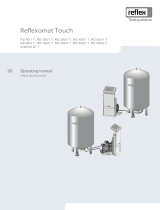
Design and connection dimensions
1 Temperature controller
– Setting range: 7 °C - 85 °C
2 Reset switch
– Switch to restart after temperature safety shut-down.
– Restart of the temperature controller after a temperature shut-down > 110 °C
3 Pilot light Indicator for the electric heater operation. Light ON = Heater in operation
RL Return flow
KW Cold water connection
WW Hot water connection
VL Supply flow

Description of the device
Storatherm Aqua Compact — 20.01.2015 Rev.1 English —
11
4.5
Identification
4.5.1
Nameplate
The nameplate provides information on manufacturer, year of manufacture, part number and technical data. The nameplate can be
found on the right side of the storage tank.
Information on nameplate
Meaning
Hot water tank, enamelled acc. to DIN 4753
Type Device name
Serial No. Serial number
Hot water Service water
Nominal volume Fill volume
Max. operating pressure Maximum working
pressure
Max. operating temperature Maximum working
temperature
Performance Indicator Duct number
Heating capacity Thermal output
Heating water Hot water end
Volume Capacity
Max. operating pressure Maximum working
pressure
Max. operating temperature Maximum working
temperature
Date of production Date of manufacture
4.5.2
Type code
No.
Type (model)
Type code
1 Storatherm Aqua Compact AC .../1-W Storage water heater with straight-tube heat exchanger
2 Storatherm Aqua Compact AC .../E-W Storage water heater with electric heating element
3 Storatherm Aqua Compact AC.../1E-W Storage water heater with straight-tube heat exchanger and
electric heating element

Technical data
12
— English Storatherm Aqua Compact — 20.01.2015 Rev.1
5
Technical data
Type
AC60/1-W
AC110/1-
W
AC160/1-
W
AC60/1E-
W
AC110/1E-
W
AC160/1E-
W
AC60/E-W
AC110/E-
W
AC160/E-
W
Nominal capacity
l 67 112 166 65 110 164 71 117 171
Diameter
mm 398
External dimensions
mm 461 x 461
Height
H mm 700 1065 1492 700 1065 1492 700 1065 1492
Height of wall
fastening
H1 533 855 1225 533 855 1225 533 855 1225
Weight
kg 52 65 91 58 71 97 51 64 90
Connection point
size for drinking
water
Cold water
KW R 3/4" 3/4" 3/4"
Hot water
WW R 3/4" 3/4" 3/4"
Connection point
size for heater
Supply flow
VL R 3/4" 3/4" -
Return flow
RL R 3/4" 3/4" -
Electric heater
Voltage
U - 400 V / 230 V
Power
P - 3000 W / 1000 W
Control range
- 7 °C - 85 °C
Shut-off device
- 110 °C
Flange
TK mm 150 ( 8 x M10)
Heating surface
m² 0.75 0.95 0.75 0.95 - -
Continuous power
KW (10°C) kW 18 23 18 23 - -
tWW = 45°C
l/h 440 566 440 566 - -
Heat exchanger
capacity
l 3.6 4.7 3.6 4.7 - -
Performance
indicator (standard
litres)
1 1.5 2.2 1 1.5 2.2 - - -
Insulation thickness
mm 30
Permissible
operating pressure
Heating
water bar 10 -
Drinking
water bar 10
Permissible
operating pressure
Heating
water °C 110 -
Drinking
water °C 95

Installation
Storatherm Aqua Compact — 20.01.2015 Rev.1 English —
13
6
Installation
Danger – electric shock!
• Risk of serious injury or death due to electric shock.
– Ensure that the system is voltage-free before installing the device.
– Ensure that the system is secured and cannot be reactivated by other persons.
– Ensure that installation work for the electric connection of the device is carried out by an electrician, and in
compliance with electrical engineering regulations.
Caution – risk of injury!
• If installation, removal or maintenance work is not carried out correctly, there is a risk of burns and other injuries at
the connection points, if pressurised hot water or hot steam suddenly escapes.
– Ensure proper installation, removal or maintenance work.
– Ensure that the system is de-pressurised before performing installation, removal or maintenance work at the
connection points.
Caution – risk of burning!
• Excessively hot surfaces in heating systems can cause burns on the skin.
– Wear protective gloves.
– Please place appropriate warning signs in the vicinity of the device.
6.1
Installation conditions
Note!
Following receipt of the goods, please check the delivery for completeness and damage. Document any damage sustained
during transportation. and contact the forwarding agent to register a complaint accordingly.
6.1.1
Installation location
Install the storage tank in a frost-proof room. If the storage tank is wall-mounted, ensure that the wall has sufficient load-bearing
capacity. If the storage tank is installed below the roof, it is recommended to use a water-collecting pan. If the storage tank is installed in
a cabinet, ensure a sufficiently dimensioned opening for ventilation.
6.1.2
Installation
Self-circulation is to be avoided. In all storage tank circuits, the pipes should be laid out so that self-circulation cannot occur. To this end,
it is recommended to install a non-return valve or check valve with return-flow preventer at all storage tank circuits.
6.1.3
Connection on "heating water" side
Connect the heating coil in counterflow mode. Do not swap supply- and return-flow connection elements. Ensure that the charging line
is as short as possible and well insulated. Provide the charging line with a drain valve.

Installation
14
— English Storatherm Aqua Compact — 20.01.2015 Rev.1
6.1.4
Connection on "water" side
Make the connection to the cold-water pipe in accordance with DIN 1988, using suitable individual fittings or a complete safety
assembly.
Attention! – Contact corrosion at the connections
Plastic inserts in the connection may be damaged during welding work.
• Ensure that the plastic inserts are neither removed nor damaged during welding work.
– For copper drinking-water connection points, use connection fittings made of brass or red bronze.
Attention! – Equipment damage
Equipment damage due to incorrect installation of the safety valve.
• Install only a type-approved safety valve.
• Adjust the safety valve settings do that the permissible working pressure cannot be exceeded.
• Install the blow-off pipe of the safety valve so that its end is positioned above a drainage point in a frost-proof
area, and is clearly visible.
• The blow-off pipe must match at least the outlet cross-section of the safety valve.
6.2
Preparatory work
Conditions for device installation:
• Frost-free, well-ventilated room.
– Room temperature range: 5 °C to 45 °C.
• Electric connection: 400 V~, 50 Hz, max. 20A. Alternatively, 230 V~, 50 Hz.
• Usage of approved transport and lifting equipment only.
6.3
Execution
Attention! – Damage due to improper installation
Bear in mind that the device may be subject to additional stresses through the connection of piping or system
equipment.
• Ensure that pipes are connected from the device to the system without stresses being induced.
• If necessary, provide support structures for the pipes or devices.
Proceed as follows when installing the device:
• Position the device.
Note!
During installation, pay attention to the operability of the valves and the inlet options for the
connecting lines.

Installation
Storatherm Aqua Compact — 20.01.2015 Rev.1 English —
15
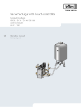
6.3.1
Hydraulic connection
Attention! – Equipment damage
Install the supplied flow pipe as required by the connection position to ensure proper functioning.
Note!
Use blind plugs to close all unused
connections.
–
Ensure that all connections are sufficiently sealed by the blind plugs.
–
Blind plugs are.not included in the scope of delivery.
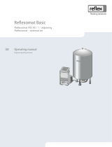
Hydraulic connection from the top: Install the flow pipe at the cold water connection (KW).
Hydraulic connection from the ground: Install the flow pipe at the hot water connection (WW).
No.
Component
No.
Component
1 Top side 5 Heating water flow
2 Bottom side 6 Hot water connection
3 Anode 7 Cold water connection
4 Flow pipe 8 Heating water return

Installation
16
— English Storatherm Aqua Compact — 20.01.2015 Rev.1
6.3.2
Drinking-water expansion vessel
Install a Reflex expansion vessel in the colt water pipe between storage and safety assembly. Each time water is drawn, drinking water
must flow through the expansion vessel.
The table below serves as a guide concerning the design of the expansion vessel. Sizes can differ, depending on the net capacities of the
individual makes of the vessels. The specifications are based on a storage temperature of 60 °C or 70 °C.
Safety-valve response
pressure
6 bar
7 bar
8 bar
10 bar
Storage-tank temperature
60°C
70°C
60°C
70°C
60°C
70°C
60°C
70°C
Storage-tank capacity
Type
Type
Type
Type
50
DD8 DD8 DD8 DD8 DD8 DD8 DD8 DD8
110
DD8 DD8 DD8 DD8 DD8 DD8 DD8 DD8
160
DD18 DD25 DD8 DD8 DD8 DD12 DD8 DD12
200
DD18 DD25 DD12 DD12 DD8 DD12 DD8 DD12
6.4
Electrical connection
Danger – electric shock!
• Risk of serious injury or death due to electric shock.
– Ensure that the system is voltage-free before installing the device.
– Ensure that the system is secured and cannot be reactivated by other persons.
– Ensure that installation work for the electric connection of the device is carried out by an electrician, and in
compliance with electrical engineering regulations.
Danger – electric shock!
• Risk of serious injury or death due to electric shock. Some parts of the main board may still carry 230V voltage even
with the device physically isolated from the 230 V power supply.
– Before you remove the covers, completely isolate the device controller from the power supply.
The following descriptions apply to standard systems and are limited to the necessary user-provided connections. Shut down the system
and secure it against unintentional reactivation. When all connections have been made according to the terminal diagram, install the
cover and connect the the mains cable with the appropriate power supply (400 V, 3000W heating power or 230 V, 1000W heating
power).

Installation
Storatherm Aqua Compact — 20.01.2015 Rev.1 English —
17
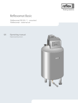
6.4.1
Terminal diagram
400 V terminal plan
230 V terminal plan

Commissioning
18
— English Storatherm Aqua Compact — 20.01.2015 Rev.1
7
Commissioning
7.1
Checking the requirements for commissioning
The device will be ready for commissioning when the tasks described in the "Installation" chapter have been completed. The system
designer or an assigned expert is responsible for carrying out the commissioning. Commission the storage tank according to the
information in the corresponding installation manual. Note the following information on commissioning:
7.2
Information from system designer
Attention! – Equipment damage
Device damage due to a closed safety valve.
• Do not close the safety valve.
The responsible installer shall explain to the operator how the hot-water storage tank functions and how it is to be used. He/She shall
draw attention to maintenance work that has to be carried out at regular intervals (which has a bearing on service life and operational
reliability). If at risk from frost, or prior to being shut down, the storage tank is to be emptied. During the heating phase, water escapes at
the safety valve - this is perfectly normal.
7.3
Filling the storage tank
Prior to the storage tank being filled for the first time, rinse out the piping and connect the storage tank. With the hot water tap open,
the storage tank is to be filled until water starts to escape. The threaded connection fittings are to be checked for tightness, and re-
tightened as necessary.
7.4
Removal from service
The storage tank is to be shut down according to the information in the operating manual for the heating device. If at risk of damage
from frost, or prior to being shut down, the storage tank is to be emptied.

Electric operation
Storatherm Aqua Compact — 20.01.2015 Rev.1 English —
19
8
Electric operation
8.1
Operating modes
No.
Component
1 Pilot light Indicator for the electric heater operation. Light ON = Heater in operation
2 Temperature
controller
Setting range: 7 °C - 85 °C
– Recommended: 65 °C (Eco operation)
3 Reset switch Switch to restart after temperature safety shut-down.
Restart of the temperature controller after a temperature shut-down > 110 °C

Maintenance
20
— English Storatherm Aqua Compact — 20.01.2015 Rev.1
9
Maintenance
Caution – risk of burning!
• Risk of burning due to escaping medium.
– Maintain a sufficient distance from the escaping medium.
– Wear suitable personal protective equipment (safety gloves and goggles).
Danger – electric shock!
• Risk of serious injury or death due to electric shock.
– Ensure that the system is voltage-free before installing the device.
– Ensure that the system is secured and cannot be reactivated by other persons.
– Ensure that installation work for the electric connection of the device is carried out by an electrician, and in
compliance with electrical engineering regulations.
9.1
Protective anode
The protective magnesium anode provides a minimum degree of protection in case of cracks in the enamel coating, in accordance with
DIN 4753. A first inspection should be made after two years of operation at the latest.
The drinking water must have a minimum conductivity of 100 μS/cm; otherwise, anode-based protection cannot be guaranteed.
If the anode has worn down by more than 2/3, it must be replaced immediately. The storage tank must be de-pressurised while doing
this. Pay attention to the existing electrical connections when making the replacement.
9.2
Draining
Prior to cleaning or repairing the storage tank, disconnect it from the water network and drain it. If necessary, drain the heating register
too.
9.3
Cleaning & decalcification
The degree of calcification of a hot-water storage tank depends on the usage duration, the operating temperature and the water
hardness.
9.4
Restarting
Thoroughly rinse out the storage tank following cleaning or repair work. Vent the individual water circuits.
9.5
Disassembly
Prior to dismantling, block off all "water"-side connections to the device. De-pressurise the device by venting it. Then disconnect the
device from all electrical power sources.
• Disconnect the system from all electrical power sources and secure it against inadvertent reactivation.
• Drain all water from the device.
– The device must be de-pressurised and empty.
• Detach the power cable of the device from the power supply point.
• Disconnect all cables from the terminals of the device control unit and remove them.
/