Page is loading ...

1
We know conveyor.
SYSTEMS • SOLUTIONS • SERVICE
(870) 935.3700
(870) 931.1877
WWW.HYTROL.COM
2020 HYTROL STREET
JONESBORO, ARKANSAS 72401
A:
T:
F:
W:
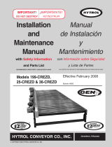
E24™ 3.0 CARD | QUICK START GUIDE
EZLOGIC® CONTROLLER CONNECTOR
(CONECTOR DEL CONTROLADOR EZLOGIC)
DC (-)
(CORRIENTE DIRECTA DC (-)
+24V DC INPUT
(ENTRADA DE CORRIENTE DIRECTA +24V DC)
MOTOR RUNNING OUTPUT
(SALIDA DE MOTOR EN FUNCIONAMIENTO)
ANALOG SPEED INPUT
(SALIDA DE VELOCIDAD ANALÓGICA)
MOTOR DIRECTION
(DIRECCION DEL MOTOR)
MOTOR RUN
(ARRANQUE DEL MOTOR)
MOTOR CONNNECTOR
(CONECTOR DEL MOTOR)
MOTOR CABLE
(CABLE DEL MOTOR)
RED L.E.D. (FAULT)
[INDICADOR LED ROJO (FALLA)]
GREEN L.E.D.
(POWER CONNECTED)
INDICADOR LED VERDE (POTENCIA CONECTADA)
SW2-1
SW2-2
SW2-3
SW2-4
SW2-5
ON
(PRENDIDO)
RED L.E.D. (FUSE)
[INDICADOR LED ROJO (FUSIBLE)]
DC (-)
(CORRIENTE DIRECTA DC (-)
SW1-1
SW1-2
SW1-3
AMBER L.E.D. (INIDCATES CURRENT LIMITING)
[INDICADOR LED NARANJA (INDICA CORRIENTE LIMITADA)]

2
MOTOR CONNECTION HEADER
E24™ motors come with a built-in 22.0 inch or 72.0 inch connection cable,
depending on the motor selected. Do not disassemble this cable. If the
cable becomes damaged and on-site repairs are required, refer to the
following wiring sequence from pin one (1) on the left through pin eight (8)
on the right.
CAUTION: Use of extension
cables may cause permanent
damage and will void the
product warrant.
Motor connection cable must
be oriented as shown.
DC POWER INPUT HEADER
A 2-pin Phoenix PT1.2/2-PVH-3.5 plug is supplied. The Hytrol 3.0 card
operates off of a +22 to +28 Volt DC power supply. The control reads the
conguration switches only when the unit is powering up. Make the power
connection only after all other connections have been made.
Pin: Signal:
1 +22 to +28 Volts DC
2 DC Ground
NOTE: When adjacent zones are operating from separate power supplies
you should connect their DC grounds. However, do not connect the positive
voltage wires from separate power supplies together.
OPTIONAL INPUT-OUTPUT (I/O) CONNECTION
HEADER
A 5-pin Phoenix PT1.5/5-PVH-3.5 plug
is supplied. If these I/O connections are
not being used, leave the connector in
place to avoid accidentally shorting the
pins.
M8 CONNECTOR FOR EZLOGIC
®
This M8 connector is already congured for use with the Hytrol EZLogic
®
control.
MOUNTING PLATE/HEAT SINK
This component is for mounting the control assembly to the conveyor frame
using two 1/4 inch, or 0.25 in, bolts while keeping the controller cooler.
CAUTION: If mounting the control on a curved section of conveyor, use
washers between the mounting plate and the conveyor frame. This
is to assure that the mounting plate is not distorted, causing damage
to the enclosed printed circuit board assembly. For best thermal
performance mount the controller on a at surface.
CONFIGURATION SWITCHES
The controls reads the conguration switches only when the unit is
powering up. To change a setting, disconnect power, set the switch,
and then reconnect power. The OFF position is to the LEFT. The ON
position is to the RIGHT.
This switch sets the
control into a Low or
High current limit mode.
The current limit differs
depending on which
motor is selected by
SW2-5.
FEEDBACK LED INDICATORS
The control board contains four (4) LED feedback indicators. These LEDs
are often useful in diagnosing various wiring and connection problems. If
power is connected there will always be at least one LED illuminated or
ashing. When no LED is illuminated, there is no power.
• One (1) Red Fuse LED
This LED is off under normal circumstances. It illuminates
constantly if the 15 amp replaceable fuse is blown and power is
applied with the proper polarity. The 15 amp fuse on the board is
not user-accesible. If the blown fuse LED is illuminated, return
the board to your Integrator for analysis or repair.
• One (1) Red Fault LED
This LED is off under normal circumstances. If a problem is
detected, it provides one of the following ve signals:
• One (1) ash in 4 seconds: The board has a hardware problem.
Return it to your supplier.
• Two (2) ashes in 4 seconds: The input voltage is too high.
Reduce the voltage.
• Three (3) ashes in 4 seconds: The input voltage is too low.
Increase the voltage.
• Four (4) ashes in 4 seconds: There is a problem with the motor
cable or connection. Check to see that the cable is not damaged
and that all of the wires are secure. If the cable has been cut or
the wires disconnected refer to the Motor Connection Header.
• Five (5) ashes in 4 seconds: Control over temperature.
• Six (6) ashes in 4 seconds: Extreme over current.
• Constantly ON: The motor is stalled or the sensor is continuously
blocked. Check for mechanical obstructions.
• One (1) Amber Motor Current Limiting LED
• Four ashes in 4 seconds: Components on the board have
overheated and the circuit is limiting the power to the motor
to about half (50%) of normal. This problem will correct itself
when the board has cooled adequately. Check for mechanical
obstructions.
• Constantly ON: Motor current is at the maximum allowed and is
being electronically limited. Check for mechanical obstructions.
• Flickering: If the motor starts under signicant load, the current
may be limited briey causing the LED to icker. If the LED
ickers constantly, this is an indication that the motor is operating
at its upper limit and may never reach the full speed. This is not a
cause for concern and no corrective action is required.
• One (1) Green Power LED
• Constantly ON: Power is properly applied as long as the fuse
is not blown.
COVER
The cover can help reduce the severity of damage to the controller from
foreign objects.
CAUTION: Removal of the cover will void the warranty. The cover does not
make the controller waterproof or dustproof.
8-PIN MOTOR
CONNECTOR
(8-PIN MOTOR
CONNECTOR)
CABLE
CONNECTOR
PLUG
(CABLE
CONECTOR
ENCHUFE)
ITEM 1
CAUTION: Power must be applied
with the proper polarity to avoid
potentially damaging the controller.
NOTE: All inputs and outputs except
analog are PNP only and are active at
+18 VDC or higher
SW2-5
100W24 125W24
Limit SW1-3 Off On
Low Off 1.5 A RMS 2.0 A RMS
High On 3.0 A RMS 4.0 A RMS
Switch
Conguration
Selection
1-1
CCW/CW
Direction
1-2
Braking/ZMH
or Coast
1-3
Current Limit
Selection
2-1
Motor Speed
Selection
2-2
2-3
2-4
2-5
Motor Type
Selection
Pin: Description:
1 Run (Input)
2 Reverse (Input)
3 Analog Input +
4 Running (Output)
5 DC Ground

3
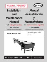
190-E24 INSTALLATION GUIDE
6. CONNECT USER I/O
(OPTIONAL)
1. MOUNT THE CONTROL
Mount the control in a location where the motor cable reaches the connection header without putting strain on
the cable connector or the header.
4. SELECT THE BRAKING ACTION
Identify the type of braking required and then set SW1-2.
Dynamic Braking with
Zero-Motion Hold
Coasting
Stop:
OFF ON
3. SELECT A SPEED
Four switches determine the operating
speed, making it simple to match
speeds in multiple zones. The actual
speed selected also depends on the
motor that you selected in the previous
step, so set those switches rst.
There is also an option to use a
0-10 VDC input for remote, dynamic
speed adjustment while the system is
running.
Switches 100W24 125W24
SW2-1 SW2-2 SW2-3 SW2-4 RPM
Standard
(FPM)
Speedup
(FPM)
RPM
Standard
(FPM)
Speedup
(FPM)
OFF OFF OFF OFF 280 140 200 350 175 255
ON OFF OFF OFF 265 130 190 331 165 240
OFF ON OFF OFF 250 125 180 312 155 225
ON ON OFF OFF 235 115 170 293 145 210
OFF OFF ON OFF 220 110 160 274 135 200
ON OFF ON OFF 205 100 145 255 125 185
OFF ON ON OFF 190 95 135 236 115 170
ON ON ON OFF 175 85 125 217 105 155
OFF OFF OFF ON 160 80 115 198 95 140
ON OFF OFF ON 145 70 105 179 85 130
OFF ON OFF ON 130 65 90 160 80 115
ON ON OFF ON 115 55 80 141 70 100
OFF OFF ON ON 100 50 70 122 60 85
ON OFF ON ON 85 40 60 103 50 75
OFF ON ON ON 70 35 50 84 40 60
ON ON ON ON 55 25 40 65 30 45
5. SELECT THE ROTATION
Identify the proper direction of rotation for the motor shaft in order to move objects from the upstream (entry)
end of the conveyor towards the downstream (exit) end of the conveyor. The direction of rotation is dened
when viewed from the back side of the motor with the shaft extending away from the viewer.
• For clockwise rotation, set SW1-1 to the ON position.
• For counter-clockwise rotation, set SW1-1 to the OFF position.
2. SELECT A MOTOR
Select the motor you will be using. Properly match the control
settings to the motor in use to deliver the best and most
predictable performance (SW2-5).
In addition to the standard 100 watt E24™ motor, this control
provides maximum performance with Hytrol’s 125 watt E24™
motor at its higher speed.
Current limit: This switch sets the control into a Low or High
current limit mode. The current limit differs depending on which
motor is selected by SW1-3
SW2-5: Motor: Comments:
OFF 100W24 Previously STD
ON 125W24 Previously HO
SW2-5
100W24 125W24
Limit SW1-3 Off On
Low Off 1.5 A RMS 2.0 A RMS
High On 3.0 A RMS 4.0 A RMS
PNP Run Input: This connection is OR’ed with Hytrol EZLogic
®
input. When either is active the motor will run.
PNP Reverse Input: When this input is active and either the PNP Run input or the EZLogic
®
input is active, the
motor will run in the opposite direction from the setting on SW1-1.
PNP Running Output: This output is active when either the PNP Run input or the EZLogic
®
input is active,
regardless of the condition of the PNP Reverse input.
Analog +(0-10VDC) Input: This input may be used to override the speed set by switches SW2-1 through
SW2-4.
• If the input is below 0.5 VDC, the speed defaults to that set by the switches.
Note: The voltage drop across the return cable will cause the set voltage to vary.
• If the input is 9.0 VDC or higher, the speed will be the maximum speed for the motor type.
• If in the range of 0.5 to 9.0 VDC, the speed will be proportional to the input within the full speed
range of the motor selected.
Unlike the switches, this input is dynamic and may be changed while the motors are operating.
Note: This input is referenced to the DC ground connected to pin 2 on the Power Input Connector.
DC Ground: This point is common to the DC ground on pin 2 of the Power Input Connector, should it be
required for reference.

We know conveyor.
SYSTEMS • SOLUTIONS • SERVICE
(870) 935.3700
(870) 931.1877
WWW.HYTROL.COM
2020 HYTROL STREET
JONESBORO, ARKANSAS 72401
A:
T:
F:
W:
For more information, please contact your local Hytrol Integration Partner.
/