
PLS600
1. Safety Summary
The following safety precautions apply to both operating and
maintenance personnel and must be observed during all phases
of operation, service, and repair of this instrument. Before
applying power, follow the installation instructions and become
familiar with the operating instructions for this instrument.
Failure to comply with these precautions or with specific
warnings elsewhere in
t
his manual violates safety standards of
design, manufacture, and intended use of the instrument.
XP Power assumes no liability for a customer’s failure to comply
with these requirements.
GROUND THE INSTRUMENT
To minimize shock hazard, the instrument chassis and cabinet must be connected to an electrical ground. This instrument is
grounded through the ground conductor of a three-conductor AC power
cable. T
he power cable must be plugged into an
approved three-conductor electrical outlet. Do not alter the ground connection. Without the protective ground connection, all
accessible conductive parts (including control controls) can render an electric shock. The power jack and mating plug of the
provided power cable meet IEC safety standards.
DO NOT OPERATE IN AN EXPLOSIVE ATMOSPHERE
Do not operate t
he instrument in the presence of flammable gases or fumes. Operation of any electrical instrument in such an
environment constitutes a definite safety hazard.
KEEP AWAY FROM LIVE CIRCUITS
Instrument covers must not be removed by operating personnel. Component replacement must only be made by qualified
maintenance personnel. Removal of the cover will void the warranty. Under certain conditions, even with the power cable
removed, dangerous voltages may exist. To avoid injuries, always disconnect power and discharge circuits before touching
them.
DO NOT SERVICE OR ADJUST ALONE
Do not attempt any internal service. This unit contains no user serviceable components. Removal of the cover will void the
warranty.
DO NOT SUBSTITUTE PARTS OR MODIFY THE INSTRUMENT
Do not install substitute parts o
r perform any unauthorized modifications to this instrument. Return the instrument to XP Power
for service and repair to ensure that safety features are maintained.

2
2. Warnings & Cautions
WARNING and CAUTION statements, such as the following examples, denote a hazard and appear throughout this manual.
Follow all instructions contained in these statements.
A WARNING statement calls attention to an operating procedure, practice, or condition, which, if not followed correctly,
could result in injury or death to personnel.
A CAUTION statement calls attention to an operating procedure, practice, or condition, which, if not followed correctly, could
result in damage to or destruction the product.
WARNING: Do not alter the ground connection. Without the protective ground connection, all accessible conductive parts
(including control controls) can render an electric shock. The power jack and mating plug of the power cable meet IEC safety
standards.
WARNING: Removing t
he instrument cover and/or replacing any internal components will void the warranty of the instrument
unless it is done by an authorized service technician.
CAUTION: Before connecting the line cord to the AC mains, check the top cover AC line voltage ratings. Applying a line voltage
other than the indicated voltage can damage the unit. For continued protection, replace fuses only with those of t
he exact same
voltage and current ratings.
CAUTION: This product uses components which can be damaged by electro-static discharge (ESD). To avoid damage, be sure
to follow proper procedures for handling, storing and transporting parts and subassemblies which contain ESD-sensitive
components.
3. Store/Move/Maintain
Storage
When this power supply is not in use store it in an environment suitable for storage (
see specifications page).
Freight
When shipping this power supply, repack it in the original packaging. If the packaging material is lost, use equivalent packing
materials to protect it during shipping.
Maintenance
Please return the power supply to XP Power or an authorized service center for any repair, service, or maintenance.
Disposal
When the power supply is in an unusable condition and can’t
be repaired, please discard it according to your company’s
disposal procedures or local legal procedures. To avoid polluting the environment, please do not discard arbitrarily.

3
Section Content Page No.
1 Safety Summary 1
2 Warnings & Cautions 2
3 Store/Move/Maintain 2
4 Preface 4
4.1 Product Summary 4
4.2 Features 4
4.3 Specification 5
5 Caution Before Using 7
5.1 Check and confirm accessories before using 7
5.2 Operating instructions 7
5.3 Ambient environment 7
5.4 Storage 7
5.5 Power-line voltage 7
5.6 Fuses 7
5.7 Power-off procedure 8
5.8 Low voltage input 8
5.9 Output lead wires and connections 8
6 Front Panel 9
6.1
Front Panel 9
7 Operating Instructions 10
7.1 Normal operation 10
7.1.1 Power on 10
7.1.2 Enabling output 10
7.1.3 Adjusting voltage and current 11
7.1.4 Displaying set points 11
7.1.5 Adjusting over voltage, over current and over power protection 11
7.2 Power Supply Set Up 12
7.2.1 Introduction 12
7.2.2 Mode 14
7.2.3 Auto start setup 16
7.2.4 Remote sense setup 17
7.2.5 Power limit setup 20
7.2.6 Over limits 21
7.2.7 LAN setup 23
7.2.8 Series and parallel operation 24
7.2.9 Calibration 27
Appendix A Analogue control inputs 32
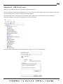
Appendix B USB control input 33
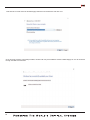
Appendix C Communication over LAN 35
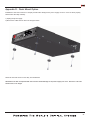
Appendix D Rack mount option 37
Appendix E Error messages 39
Service Information 42
Limited 3 Year Warranty 43

4
4. Preface
4.1 Product Summary
The PLS600 is a programmable DC power supply with single output that offers a maximum power output up to 600 watts. With
12-bit D/A & A/D converters embedded, the power supplies come with the capability of reporting voltage and current very
accurately.
The PLS600 series provides convenient digital rotary controls for voltage and current adjustment. The power supplies also c
ome
with rear ports that allow remote control via USB, Ethernet, and analog control inputs. The USB and Ethernet inputs are SCPI
compliant and have LabView drivers available on the National Instruments website. See Appendix A and Appendix B for details.
The PLS600 series is also LXI certified, details for using this interface can be found in the Programming Manual.
The PLS600 series also provide
a s
ophisticated scripting ability that allow the user to write programs and upload them to the
power supply. The PLS600 will then execute the programs on command. Details can be found in the PLS600 scripting language
manual.
4.2 Features
1. Output Voltage & Current
2. Rotary Controls
The digital rotary controls allow both fine and rapid adjustment of the output voltage and current. The controls are velocity
sensitive so that a slow turn of the control allows fine adjustment of voltage or current and rapid turning quickly adjusts voltage
or current over a large range.
3. Precise voltage and current measurement
The PLS600 series also offers the capability to measure
voltage & current accurately (read back), saving users the extra
expense and space for extra measuring instruments. This capability is available from the display or the readings may be read
into the controlling device.
4. OVP (over voltage protection), OCP (over current protection) and OPP (over power protection) functions
The over voltage protection (OVP), over current protection (OCP) and over power protection (OPP) features limit the maximum
output current and voltage to avoid damage to the unit under test (UUT).
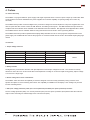
Model Voltage Current Power
PLS6003033 30 33
600 W
PLS6005020 50 20
PLS60010010 100 10
PLS6002005 200 5
PLS6004002.5 400 2.5

5
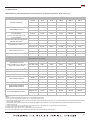
4.3. Specifications
Unless otherwise noted, specifications are warranted over the ambient temperature range of 0 to 40 ºC.
Notes:
1. Minimum voltage is guaranteed at greater than 1% of the rated output voltage.
2. Minimum current is guaranteed at greater than 1% of the rated output current.
3. Measured with 20 MHz bandwidth and excluding line frequency ripple (see application note AN024 for measurement details, these measurements taken at full rated
output voltage and full power.
4. Line frequency ripple measured with 20 MHz bandwidth (see application note AN024 for measurement details, these measurements taken at full rated output
voltage and full power.
5. Time for output voltage to recover within 0.5% of its rated output for a load change from 10 to 90% of its rated output current.
6. Voltage set point from 10% to 100% of rated output
7. Add this to the output response time to obtain the total programming time
8. Time to provide data back to the controller using LAN interface (does not include A/D conversion time)
PLS6003033 PLS6005020 PLS60010010 PLS6002005 PLS6004002.5
DC Output Ratings
(1)
Voltage 30 V 50 V 100 V 200 V 400 V
Current 33 A 20 A 10 A 5 A 2.5 A
Power 600 W 600 W 600 W 600 W 600 W
Output Ripple & Noise
CV p-p
3
60 mV 100 mV 100 mV 100 mV 200 mV
CV rms
4
20 mV 100 mV 150 mV 150 mV 50 mV
Load Regulation
(change from 10%-90% load)
Voltage 15 mV 25 mV 50 mV 100 mV 200 mV
Current 15 mV 15 mV 15 mA 15 mA 15 mA
Line Regulation
(change from 100-132 VAC input or
180-260 VAC input)
(5)
Voltage 15 mV 25 mV 50 mV 100 mV 200 mV
Current 15 mV 15 mV 15 mA 15 mA 15 mA
Programming Accurancy
(1,2)
Voltage 0.1%+ 15 mV 25 mV 50 mV 100 mV 200 mV
Current 0.1%+ 66 mA 40 mA 20 mA 10 mA 5 mA
Measurement Accuracy
Voltage 0.1%+ 15 mV 25 mV 50 mV 100 mV 200 mV
Current 0.1%+ 60 mA 40 mA 15 mA 10 mA 5 mA
Transient Recovery Time
(5)
Time ≤1 ms ≤1 ms ≤1 ms ≤1 ms ≤1 ms
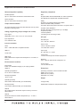
Supplemental Characteristics (supplemental characteristics are not warranted but are descriptions of typical performance determind
either by design or type testing)
Output Response Time
(settle to within ±1% of the rated
output, with resistive load)
Up, Full Load 0.08 s 0.08 s 0.08 s 0.08 s 0.08 s
Down, Full Load 0.08 s 0.08 s 0.08 s 0.08 s 0.08 s
Down, No Load 0.5 s 0.5 s 0.5 s 0.5 s 0.5 s
Command Response Time
(7)
50 ms 50 ms 50 ms 50 ms 50 ms 50 ms
Data Readback Transfer Time
(8)
5 ms 5 ms 5 ms 5 ms 5 ms 5 ms
Remote Sense Compensation
Volts/Load Lead 1 V 1 V 2 V 4 V 4 V
Over-voltage Protection
Range 0.5-33 V 0.5-55 V 0.5-110 V 0.5-220 V 0.5-440 V
Accuracy 0.3 V 0.5 V 1 V 2 V 4 V
Output Ripple & Noise
(3)
CC rms 7 mA 5 mA 5 mA 5 mA 10 mA
Programming Resolution
Measurement Resolution
Voltage 0.05%+ 10 mV 25 mV 50 mV 100 mV 200 mV
Current 0.05%+ 20 mA 20 mA 10 mA 5 mA 2.5 mA
Front Panel Display Accuracy
Voltage 0.1%+ 10 mV 25 mV 50 mV 100 mV 200 mV
Current 0.1%+ 33 mA 20 mA 10 mA 5 mA 2.5 mA

6
Series and parallel capability
Parallel operation
Up to 4 units can be connected in master/slave mode
Series operation
Up to 2 units can be connected in series
Output terminal isolation
No output terminal may be more than 600 VDC from any other
terminal or chassis ground
Analog programming (output voltage and current)
Input signal
Selectable; 0 to 3 V, 0 to 5 V or 0 to 10 V full scale
Input impedance
0 to 10 kΩ f
ull scale
Interface capabilities
GPIB
SCPI – 1993, IEEE 488.2 compliant interface
USB 2.0
10/100 LAN
Web server
Built-in Web server requires Internet Explorer 5+ or Firefox, or
Chrome
Environmental conditions
Environment
Indoor use, installation category II (AC input), pollution
degree 2
Operating temperature
0°C to 40°C @ 100% load
Storage temperature
–20°C to 70°C
Operating humidity
30% to 90% relative humidity (
no condensation)
Storage humidity
10% to 95% relative humidity (no condensation)
Altitude
Up to 3000 meters. Derate the output current by 2%/100 m
above 2000 m.
Altitude
Derate the maximum ambient temperature by 1 °C/100 m
above 2000 m.
Regulatory compliance
EMC
European EMC directive 89/336/EEC for Class A products
This ISM device complies with Canadian ICES-001.
Safety
European Low Voltage Directive IEC 60950
U
S and Canadian safety standards
Any LEDs used in this product are Class 1 as per IEC 825-1
Acoustic noise declaration
Emission directive: Sound pressure Lp <70 dB(A),
At operator position,
*Normal operation,
*According to EN 27779 (Type Test).
AC input
Nominal input
100 – 240 VAC; 50/60 Hz
Input current
7.5 A @ 100 VAC nominal;
4 A @ 200 VAC nominal
Input range
90 – 265 VAC; 47 – 63 Hz.
Power factor
>0.95 a
t nominal input and rated output power
Efficiency
76% – 85% for 600 W units at full power out
Inrush current
<20 A for 600 W units;
Dimensions
(excluding connectors, control controls and feet.
Height 44 mm (1.73 in)
Width 224 mm (8.82 in)
Depth 262 mm (10.3in)
Weight
2.7Kg (6.0 lbs.)
Specifications subject to change without notice.
Supplemental Characteristics For All Model Numbers

7
5. Caution Before Using
5.1 Check Condition before Using
After receiving this product, please verify that the item received is without scratch or other damage.
5.2 Operating Instructions
In order to avoid damaging the instrument due to improper operation, be sure to read this user manual. To maintain the specified
accuracy, calibration should be performed annually.
5.3 Ambient Environment
1. Do not locate or operate this product in an environment with dust, vibration, or corrosive gas and do not expose this product
directly to the sunlight. Operate it in an environment with temperature 0-40°C and relative humidity 20%-80%. The power
supply will sense an over temperature condition and will shut off output power and display an error message should an over
temperature occur.
2. This product is equipp
ed w
ith one cooling fan with intake vents on the top and sides of the chassis and outlet vents on the
rear and side of the chassis. Provide at least 1 inch of open space at the vents with good ventilation. If the units are stacked
do not block the side air intakes. Never block the rear air outlets.
3. The product is designed with a power line filter to minimize noise into the instrument from the AC p
ower source and to
minimize noise output to the line. The power supply is also protected from moderate power transients and ESD on its
terminals. If the power supply will be exposed to large transients, external protection should be provided.
5.4 Storage
The storage temperature range of this product is within -40ºC to +70ºC and R.H. should be 20% to 80% without moisture
condensing. If not operating t
his product for a long time interval, pack it with original packaging or similar one and put it in a dry
place without exposure to direct sunlight.
5.5 Power-line voltage
Rated AC power source connected to this product is within 90 - 265 VAC 47 - 63 Hz (refer to the Product Specification for
details). Before connecting to external power source, be sure that the power switch is in OFF state and verify t
hat the provided
power cord is firmly attached to the power source and to the instrument.

8
5.6 Fuses
This product is a switching mode power supply. The fuse installed is there to protect the power supply in case of excessive input
voltage or internal hardware failure. The fuse should not open during normal operation. In the fuse does open, it indicates a
malfunction. In this case, it is suggested that the product be sent back for service.
WARNING: If the fuses are replaced they must be replaced w
ith the exact make, model and rating fuse. Failure to do this
may cause a safety hazard and may invalidate the warranty.
CAUTION: DOUBLE POLE/NEUTRAL FUSING. Disconnect power before servicing.
In order to avoid damaging the instrument due to improper operation, be sure to read this user manual. To maintain the specified
accuracy, calibration should be performed annually.
5.7 Power-off procedure
When the supply is not in use, be sure to turn the power switch on the panel to the OFF position to turn off the AC power. After
the power switch is turned to the OFF position, the inner fans will still run for up to 15 seconds. Once the discharge process is
complete, the power supply will shut down.
5.8 Low Voltage Input
When the AC input voltage is lower than the minimum rated voltage which is 90 VAC, the supply will deactivate internal circuitry
and will not operate. To ensure proper operation, confirm that the input AC voltage is within the specified range.
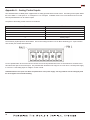
5.9 Output Lead Wires and Connections
The PLS600 power supply is capable of supplying very high currents and care should be taken to size the output leads and
connectors appropriately. Refer to the following table for suggested wire sizes:
M
ost banana plugs are not rated for more than 15 amps. If you are using in excess of 15 amps please check the rating of the
banana plug you are using. A source of 30 amp banana plugs is at the following URL:
http://www.parts-express.com/parts-express-gold-plated-screw-type-banana-plugs-14-8-awg-16-pcs--091-354
Maximum Current AWG
33 10
20 14
10 18
5 22
2.5 24

9
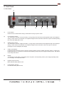
6. Front Panel
6.1 Front Panel
(1) Power Switch:
Please consult “Cautions Before Using” section before turning on power switch.
(2) Current Rotary Control:
Turn clockwise to increase current limit setting. Turning slowly will increment the least significant digit of the displayed
setting. As the control is turned faster more significant digits will be incremented. When the output is activated pressing
th
is c
ontrol will display Set Current.
(3) Voltage Rotary Control:
Turn clockwise to increase voltage limit setting. Turning slowly will increment the least significant digit of the displayed
setting. As the control is turned faster more significant digits will be incremented. When the output is activated
pressing this control will display Set Voltage.
(4) Output On/Off Button:
Pushing this button after
the p
ower to the power supply has been turned on enables the output voltage. Pressing and
holding this button for more than 5 seconds and then releasing will put the power supply into Setup mode. See section
8.2 for setup instructions.
(5) Display:
16 character by 2 line display. This display shows set points, actual operating values, power supply operating status,
error messages, and setup informati
on.
(
6) Negative Output Terminal
Black Standard Safety Banana Jack
(7) Positive Output Terminal
Red Standard Safety Banana Jack
7
6
5 4 3 2 1

10
7. Operating Instructions
7.1 Normal Operation
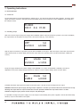
7.1.1 Power On
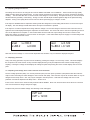
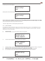
Connect the power input to the appropriate AC voltage source. Turn the Power Switch to the ON (I) position. On power up the
supply will execute a self-test. During the self-test the display will show the voltage and current capabilities of the supply and
the software revision.
PLS600
100 V 6 A V1.00
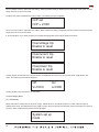
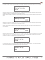
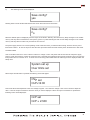
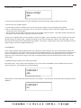
7.1.2 Enabling Output
After Power On the output of the power supply will be disabled until the output on/off button is pushed. The screen will display
the output status, the set points currently in force, and control mode (e.g., Local, Remote).
OFF Ioc
V=100.0 i=3.500
Until the output on/off button is pressed no power will be available on the output. When the output on/off button is pressed the
output will be turned on and the display will show the output status, the operating mode, and the actual output voltage and
current.).
on vmode Ioc
V=100.0 i=1.654
The power supply will always be in either voltage mode (VMODE) or in current mode (IMODE or PMODE). This state is
dependent on the power supply settings and the load. When in current mode the display will be as shown below.
To disable the output simply press the output on/off button again – this will remove all voltage from the output.
WARNING: Because the power supply has large output capacitors it can take up to 30 seconds for the internal circuit to fully
discharge the output after the output on/off button has been pressed to disable the output when there is no load.
Hazardous voltages may be present until the output i
s fully discharged.
It is possible to configure the power supply to turn the output on automatically when power is applied. See the Auto Start Setup
section (7.2.3) for further details on this option.
on imode Ioc
V=88.2 i=3.500

11
7.1.3 Adjusting Voltage and Current
The voltage and current are set using the two controls labeled “VOLTAGE” and “CURRENT”. These controls use high quality
digital encoders rather than potentiometers. Turn the controls clockwise to increase a setting or counter clockwise to decrease
a setting. The encoders allow fine or coarse control of the voltage or current setting. The speed at which you turn
the controls
will determine the granularity of the setting. Turning at a slow rate will adjust the least significant digit of the parameter being
adjusted. Turning more rapidly allows coarse control to allow rapid changing of voltage or current.
If the output is disabled while an adjustment is being made the voltage and current setting will be shown on the normal output
off display. The new se
ttings w
ill take effect when the output on/off button is pressed.
If the output is on while an adjustment is being made the voltage or current will change in real time as the control is turned. A
special screen will be displayed during the adjustment as shown below. The screen will revert to the normal operating screen as
soon as the adjustment is complete. In the screens below the actual real-time o
utput voltage and current is shown on the
bottom line and the set voltage or current is shown in the top line. In the cases below the power supply is current limiting as the
actual current matches the set current.
Note that the actual voltage or current is load dependent and, therefore, may not match the displayed set point.
7.1.4 Displaying Set Points
At any time during operation, set points can be recalled by pressing the voltage or current rotary control. This action displays
the set points in the same manner as they would be displayed during a set point adjustment but without actually changing
anything. Pressing the voltage control displays the voltage set point and pressing the current control displays the current set
point.
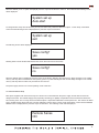
7.1.5 Adjusting Over Voltage, Over Current and Over Power Protection.
The over voltage protection (OVP), over current protection (OCP) and over power protection (OPP) features limit the maximum
output current and voltage to avoid damages to the unit under test (UUT). OVP and OCP m
ay be set as shown below or may be
changed via the setup menus. OPP may only be changed in the setup menus. Note that Over Voltage and Over Current
protection can also be adjusted in the Setup menu – section 8.2.5.
If OVP, OCP, or OPP is set to maximum that protection will be disabled. Note: OVP, OCP, and OPP cannot be set to more than
10% over the maximum rating of the power supply.
To adjust OVP p
ress and release Voltage. The following screen will appear:
Vset v=100.0
V=88.2 i=3.500
OVP set
OVP = 12.00
iset i=3.122
V=88.2 i-3.122

12
Turn the Voltage control to adjust the OVP setting. When the desired setting is displayed press the output on/off button and the
supply will revert to its previous state.
To adjust OCP press and release the Current control. The following screen will appear:
Turn the Current control to adjust the OCP setting. When the desired setting is displayed press the output on/off button and the
supply will revert to its previous state.
If, during operation, any of these set points is exceeded the appropriate screen will be displayed as below.
Pressing Output On/Off when any of the trip screens are displayed will reset the trip and put the power supply back in idle
mode. The following screen will be displayed.
Pressing Enable at this time will turn on the output.
OcP set
OcP = 2.500
Overvoltage trip
Enable to reset
System set up
mode
Overcurrent trip
Enable to reset
Overpower trip
Enable to reset
Off Ioc
V=100.0 i=3.500
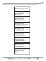
7.2 Power Supply Setup
7.2.1 Introduction
Setup mode allows configuration of the power supply. Within setup one can adjust the power on state, select I/O options,
enable remote sense, and calibrate the power supply. To enter setup mode press and hold the output on/off button for at least 5
seconds. When enabled the initial setup screen will appear

13
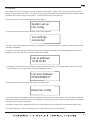
Releasing the output on/off button will allow the user to scroll through the setup options by rotating either control.
System set up mode
System set up
Auto-start
System set up
Remote sense
System set up
POWER SETPOINT
System set up
Over limits set
System set up
LAN CONFIG
System set up
MSTER MODE
System set up
CALIBRATION
System set up
exit

14
7.2.2 Mode
See Appendix A for analog control setup, Appendix B for USB control setup, and the PLS600 USB-Analog Programming Manual
for information on serial command syntax and on LXI usage.
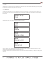
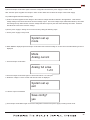
7.2.2.1 USB/Analog
The Mode menu allows the user to choose between local control or remote control. If remote control is chosen the user can
further select if the control is to be analog voltage control or USB contro
l. The Mode screen shown below is the entry point for
these choices..
System set up
mode
mode
local
Mode
remote
Mode
Analog voltage
Mode
Analog current
Mode
Analog dual
Rotating either rotary control clockwise will show the following screens:
When the desired mode is displayed press the output on/off button to select it. If LOCAL or REMOTE is selected, no further
setup is required and the display will return to the setup main menu.
If REMOTE is selected the front panel will be locked out and control will be through the Ethernet port, USB port or analog i
nputs
exclusively.

15
Analog full scale
v=10
Analog full scale
I=10
If ANALOG VOLTAGE is selected, the desired scaling of the analog voltage input must be selected and this screen will appear.
Rotating the Voltage control will allow choice of 3V, 5V or 10V scaling. When the desired option is displayed, press the output
on/off button to select it. The display will return to the setup main menu.
Similarly, ANALOG CURRENT is selected, the desired scaling o
f the analog current input must be selected and this screen will
appear.
Analog full scale
v=10 I=10
Rotating the Current control will allow choice of 3V, 5V or 10V scaling. When the desired option is displayed, press the output
on/off button to select it. The display will return to the setup main menu.
Similarly, ANALOG DUAL is selected, the desired scaling of the analog voltage and current inputs must be selected and this
screen will appear.
System set up
mode
System set up
exit
Rotating the Voltage control will allow choice of 3V, 5V or 10V scaling for the analog voltage port and rotating the Current control
will allow choice of 3V, 5V or 10V scaling for the analog current port. When the desired option is displayed, press the output
on/off button to select it. The display will return to the setup main menu.
To change another setup item at this time you may
u
se either rotary control to select that option. To exit setup, rotate either
control until the following screen is displayed then press the output on/off button.

16
Save config?
yes
The following screen will be displayed.
Save config?
no
Auto-start?
yes
Auto-start?
no
Rotating either control will alternate between the screen above and the screen below.
Rotating either control will cycle between the yes and no option.
When the desired option is displayed press the output on/off button. Selecting YES will save any Setup changes to non-volatile
memory and they will be retained even when primary power is cycled. Selecting NO will not save Setup changes to n
on-volatile
memory and they will be in effect only until the unit is turned off.
The power supply will return to normal operating mode at this time.
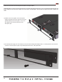
7.2.3 Auto Start Setup
The Auto Start option, when enabled, causes the power supply to immediately provide output power when the power switch is
turned on without pressing the output on/off button. The voltage and current settings will be the same as they were when the
supply was last powered off.
WARNING: In Auto Start mode hazardous voltages may be present on the power supply output immediately after power is
applied.
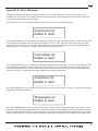
When in setup mode rotate either rotary control until the AUTO-START screen is displayed then press the output on/off button.
The following screen will be displayed.

17
System set up
Auto-start
When the desired yes or no option is displayed press the output on/off button to select it. After selection the following screen
will be displayed:
System set up
exit
To change another setup item at this time you may use either rotary control to select that option. To exit setup, rotate either
control until the following screen is displayed then press the output on/off button.
Save config?
yes
The following screen will be displayed.
Save config?
no
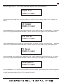
Rotating either control will alternate between the screen above and the screen below.
When the desired option is displayed press the output on/off button. Selecting YES will save any Setup changes to non-volatile
memory and they will be retained even when primary power is cycled. Selecting NO will not save Setup changes to non-volatile
memory and they will be in effect only until the unit i
s turned off.
The power supply will return to normal operating mode at this time.
7.2.4 Remote Sense Setup
Most power supplies with remote sense require a second set of wires between the power supply and the load to sense the
voltage at the load. The PLS600 supply uses proprietary technology to digitally compensate for these resistances without the
extra sensing wires. Prior to using the Remote Sense o
ption a simple load calibration must be performed. This section will detail
how to enable Remote Sense and how to do the calibration required. Once in setup mode rotate either control until the REMOTE
SENSE screen is displayed then press the output on/off button. The following screen will be displayed.
Remote Sense
ON

18
Remote Sense
OFF
Rotating either control will alternate between the ON or OFF selection. Press the Output On/Off button when the desired mode
is displayed.
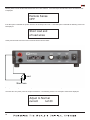
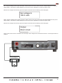
Short load end
of load wires
Adjust to Normal
current I=2.33
If the NO option is selected the system will revert to the Setup main menu. If the YES option is selected the following screen will
be displayed:
At this point the load end of the wires must be shorted as shown below:
It is important that a good short with heavy wire is made as failure to do this will result in a poor remote sense calibration.
Once the short is in place, p
ress the output on/off button. The following screen is an example of what will be displayed.
Load
Short here

19
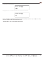
Load resistance
too great
Remote sense
retry
Remote sense
Complete 99MΩ
The error screen will be followed by:
Pressing the Output On/Off button at this time will bring the user back to the Remote Sense On screen. Remote sense must be
turned off or the load wires must be improved to allow calibration of remote sense.
If the remote sense calibration completed normally the display will return to the REMOTE SENSE COMPLETE screen.
System set up
Remote sense
Pressing Output On/Off button will now return the system to the following screen:
System set up
exit
To change another setup item at this time you may use either control to select that option. To exit setup, rotate either control
until the following screen is displayed then press the output on/off button.
Now set the current to at least as much as you would expect your load to consume. More is better if your load wires are
capable of handling the current. When ready press the out
put o
n/off button.
The power supply will now measure the output current and the total voltage drop in the load wires and use these values to
calculate the resistance of the load wires. As long as Remote Sense remains enabled the power supply will use this resistance
value to calculate output voltage based on output current. It will then adjust the output voltage at the power terminals in real
time
to c
orrect for the drop in the load cables.
If, during the remote sense setup, the lead resistance is so much that remote sense will not be able to operate reliable the
following error screen will be displayed.

20
Save config?
yes
The following screen will be displayed.
Save config?
no
System set up
Power setpoint
Power setpoint
P = 606w
System set up
exit
Rotating either control will alternate between the screen above and the screen below.
When the desired option is displayed press the output on/off button. Selecting YES will save any Setup changes to non-volatile
memory and they will be retained even when primary power is cycled. Selecting NO will not save Setup changes to non-volatile
memory and they will be in effect only until the
u
nit is turned off.
The power supply will return to normal operating mode at this time.
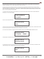
7.2.5 Power Limit Setup
The PLS600 power supply is designed to supply up to 600 watts of output power to a load. In some applications it may be
desirable to limit the maximum power to something lower than the maximum available from the power supply. This section
describes how to set up power limiting.
1) Enter setup
m
ode
2) Rotate the voltage or current control until the following screen appears.
3) Push the output on/off button and the following screen will appear.
4) Rotate the voltage or current control to adjust the maximum power that can be delivered by the supply. This may be in
the range of 1% to 101% of the maximum rating (6 watts to 606 watts for the PLS600).
5) When the power is set to the maximum desired
power i
s displayed then press the output on/off button.
6) Now rotate either control until the following screen is displayed then press the output on/off button.
Page is loading ...
Page is loading ...
Page is loading ...
Page is loading ...
Page is loading ...
Page is loading ...
Page is loading ...
Page is loading ...
Page is loading ...
Page is loading ...
Page is loading ...
Page is loading ...
Page is loading ...
Page is loading ...
Page is loading ...
Page is loading ...
Page is loading ...
Page is loading ...
Page is loading ...
Page is loading ...
Page is loading ...
Page is loading ...
Page is loading ...
-
 1
1
-
 2
2
-
 3
3
-
 4
4
-
 5
5
-
 6
6
-
 7
7
-
 8
8
-
 9
9
-
 10
10
-
 11
11
-
 12
12
-
 13
13
-
 14
14
-
 15
15
-
 16
16
-
 17
17
-
 18
18
-
 19
19
-
 20
20
-
 21
21
-
 22
22
-
 23
23
-
 24
24
-
 25
25
-
 26
26
-
 27
27
-
 28
28
-
 29
29
-
 30
30
-
 31
31
-
 32
32
-
 33
33
-
 34
34
-
 35
35
-
 36
36
-
 37
37
-
 38
38
-
 39
39
-
 40
40
-
 41
41
-
 42
42
-
 43
43


XP PLS60010010 User manual
- Type
- User manual
- This manual is also suitable for
Ask a question and I''ll find the answer in the document
Finding information in a document is now easier with AI
Other documents
-
Itech IT8516C+ User manual
-
 B & K Precision Model XLN10014-GL User manual
-
B&K Precision PVS10005 User manual
-
Agilent Technologies E3634A User manual
-
Chroma A620027 Operating & Programming Manual
-
 Chroma 62150H-600 Operating & Programming Manual
-
-
Agilent Technologies 5745A User manual
-
-
HP 6631B User manual

