Emerson 3081FG 2-Wire In Situ O2 Analyzer (550° to 1600°C)-Rev 1.5 User manual
- Category
- Oxygen Equipment
- Type
- User manual
This manual is also suitable for

Instruction Manual
IB-106-3081 Rev. 1.5
September 2002
http://www.processanalytic.com
Model 3081FG
Two-Wire In Situ
Oxygen Analyzer
(550° to 1600°C)

Emerson Process Management
Rosemount Analytical Inc.
Process Analytic Division
1201 N. Main St.
Orrville, OH 44667-0901
T (330) 682-9010
F (330) 684-4434
e-mail: gas.csc@EmersonProcess.com
http://www.processanalytic.com
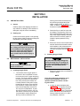
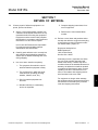
ESSENTIAL INSTRUCTIONS
READ THIS PAGE BEFORE PROCEEDING!
Rosemount Analytical designs, manufactures and tests its products to meet many national and
international standards. Because these instruments are sophisticated technical products, you
MUST properly install, use, and maintain them to ensure they continue to operate within their
normal specifications. The following instructions MUST be adhered to and integrated into your
safety program when installing, using, and maintaining Rosemount Analytical products. Failure to
follow the proper instructions may cause any one of the following situations to occur: Loss of life;
personal injury; property damage; damage to this instrument; and warranty invalidation.
• Read all instructions prior to installing, operating, and servicing the product.
• If you do not understand any of the instructions, contact your Rosemount Analytical repre-
sentative for clarification.
• Follow all warnings, cautions, and instructions marked on and supplied with the product.
• Inform and educate your personnel in the proper installation, operation, and mainte-
nance of the product.
• Install your equipment as specified in the Installation Instructions of the appropriate In-
struction Manual and per applicable local and national codes. Connect all products to the
proper electrical and pressure sources.
• To ensure proper performance, use qualified personnel to install, operate, update, program,
and maintain the product.
• When replacement parts are required, ensure that qualified people use replacement parts
specified by Rosemount. Unauthorized parts and procedures can affect the product’s per-
formance, place the safe operation of your process at risk, and VOID YOUR WARRANTY.
Look-alike substitutions may result in fire, electrical hazards, or improper operation.
• Ensure that all equipment doors are closed and protective covers are in place, except
when maintenance is being performed by qualified persons, to prevent electrical shock
and personal injury.
The information contained in this document is subject to change without notice.

HIGHLIGHTS OF CHANGES
Effective June, 1998 Rev. 1.0
Page Summary
Page 2-10 Corrected part numbers in Figure 2-9 for Flowmeter and Ref Air Set.
Page 3-4 Modified Figure 3-5 to reflect selection of additional faults.
Page 3-11 Modified paragraph 3-6a to select additional fault screens.
Page 4-4 Updated menus for O
2
value, SV, TV, and 4V values.
Page 8-1 Added in replacement part numbers for Model 3081 Transmitter.
Effective April, 1999 Rev. 1.1
Page Summary
Cover Added “Model 3081FG” to manual title.
Page 1-2 Deleted 48 in. probe and Mullite probe options from Product Matrix.
Page 1-7 Deleted 48 in. probe and Mullite probe references from specifications.
Page 2-1 through 2-6 Changed probe installation mounting and insertion procedures and
requirements.
Page 5-1 Revised PC board stack replacement procedure.
Throughout Changed all references to “power supply board” to read “analog board”.
Reformatted document in accordance with the latest style guide.
Effective October, 2000 Rev. 1.2
Page Summary
Throughout Changed all references of 38 in. (965 mm) probe to 34.625 in.
(880 mm).
Effective April, 2001 Rev. 1.3
Page Summary
Page 2-9 Added 1st WARNING to paragraph 2-3.
Page 10-2 Added drawing 1400184.
Effective January, 2002 Rev. 1.4
Page Summary
Page 8-1 Added part number for PC Board Stack Assembly.
Effective September, 2002 Rev. 1.5
Page Summary
Page 1-7 Updated process temperature limits specification.


Instruction Manual
IB-106-3081 Rev. 1.5
September 2002
Rosemount Analytical Inc. A Division of Emerson Process Management i
Model 3081FG
TABLE OF CONTENTS
PREFACE........................................................................................................................ P-1
Definitions ........................................................................................................................ P-1
Safety Instructions .......................................................................................................... P-2
1-0 DESCRIPTION AND SPECIFICATIONS........................................................................ 1-1
1-1 Component Checklist Of Typical System (Package Contents) .................................. 1-1
1-2 System Overview............................................................................................................ 1-3
1-3 Specifications................................................................................................................... 1-7
2-0 INSTALLATION .............................................................................................................. 2-1
2-1 Pre-Installation................................................................................................................. 2-1
2-2 Mechanical Installation ................................................................................................... 2-1
2-3 Electrical Installation....................................................................................................... 2-9
2-4 Pneumatic Installation .................................................................................................. 2-11
3-0 STARTUP AND OPERATION ...................................................................................... 3-1
3-1 General ............................................................................................................................ 3-1
3-2 Power Up........................................................................................................................ 3-1
3-3 Reestablishing Proper Calibration Check Gas Flow Rate......................................... 3-2
3-4 Operation ......................................................................................................................... 3-3
3-5 Program Menu ................................................................................................................3-6
3-6 Diagnostics Menu ......................................................................................................... 3-11
3-7 CALCHECK MENU ...................................................................................................... 3-13
4-0 HART/AMS...................................................................................................................... 4-1
4-1 Overview.......................................................................................................................... 4-1
4-2 HART Communicator Signal Line Connections ........................................................... 4-1
4-3 HART Communicator PC Connections ........................................................................ 4-3
4-4 Off-Line and On-Line Operations ................................................................................. 4-3
4-5 Menu Tree for HART Communicator/
Two-Wire In Situ Oxygen Analyzer Applications...................................................... 4-3
4-6 HART Communicator Start CALCHECK Method ........................................................ 4-7
5-0 MAINTENANCE AND SERVICE .................................................................................. 5-1
5-1 Model 3081 Electronics Replacement......................................................................... 5-1
5-2 Oxygen Probe Replacement ......................................................................................... 5-3
6-0 TROUBLESHOOTING .................................................................................................... 6-1
6-1 General ............................................................................................................................ 6-1
6-2 Probe Life ....................................................................................................................... 6-1
6-3 Fault Indications.............................................................................................................. 6-2
6-4 Identifying and Correcting Fault Indications ................................................................. 6-3
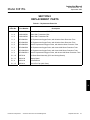
7-0 RETURN OF MATERIAL .............................................................................................. 7-1
8-0 REPLACEMENT PARTS ............................................................................................... 8-1
9-0 INDEX.............................................................................................................................. 9-1
10-0 DRAWINGS AND SCHEMATICS ............................................................................... 10-1

Instruction Manual
IB-106-3081 Rev. 1.5
September 2002
ii Rosemount Analytical Inc. A Division of Emerson Process Management
Model 3081FG
LIST OF ILLUSTRATIONS
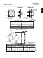
Figure 1-1. Typical System Package ....................................................................................... 1-1
Figure 1-2. Two-Wire In Situ Oxygen Analyzer HART Connections and AMS Application ..... 1-5
Figure 1-3. Typical System Installation .................................................................................... 1-6
Figure 1-4. Power Supply and Load Requirements ................................................................. 1-8
Figure 2-1. Probe Installation Details ....................................................................................... 2-2
Figure 2-2. Optional Adapter Plate........................................................................................... 2-3
Figure 2-3. Optional Probe Mounting Flange ........................................................................... 2-3
Figure 2-4. Horizontal Probe Installation.................................................................................. 2-4
Figure 2-5. Adjusting Probe Insertion Depth ............................................................................ 2-5
Figure 2-6. Flat Surface Mounting Dimensional Information.................................................... 2-7
Figure 2-7. Pipe Mounting Dimensional Information ................................................................ 2-8
Figure 2-8. Display Positioning Assembly................................................................................ 2-9
Figure 2-9. Oxygen Probe Terminal Block ............................................................................. 2-10
Figure 2-10. Model 3081 Transmitter Terminal Block.............................................................. 2-11
Figure 2-11. Oxygen Probe Gas Connections ......................................................................... 2-11
Figure 2-12. Air Set, Plant Air Connection ............................................................................... 2-12
Figure 3-1. Normal Operation Display...................................................................................... 3-1
Figure 3-2. Faulted Operation Display ..................................................................................... 3-1
Figure 3-3. Proper Calibration Check Gas Flow Rate.............................................................. 3-2
Figure 3-4. Normal Operation Display...................................................................................... 3-3
Figure 3-5. Model 3081 Transmitter Menu Tree ...................................................................... 3-4
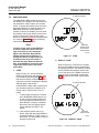
Figure 3-6. Infrared Remote Control (IRC)............................................................................... 3-5
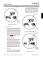
Figure 3-7. CODE..................................................................................................................... 3-6
Figure 3-8. DISPLAY CODE ................................................................................................... 3-6
Figure 3-9. FAULT VAL........................................................................................................... 3-7
Figure 3-10. UPPER RANGE VAL........................................................................................... 3-7
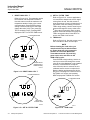
Figure 3-11. CELL T HI ............................................................................................................ 3-7
Figure 3-12. RESET MAX CELL T........................................................................................... 3-8
Figure 3-13. SET O
2
FILTER TIME.......................................................................................... 3-8
Figure 3-14. TRIM 4 mA?........................................................................................................... 3-8
Figure 3-15. TRIM 20 mA?......................................................................................................... 3-9
Figure 3-16. SET HI BOTTLE O
2
............................................................................................. 3-9
Figure 3-17. SET LO BOTTLE O
2
............................................................................................ 3-9
Figure 3-18. SET O
2
TRACKING ............................................................................................ 3-10
Figure 3-19. SET CODE.......................................................................................................... 3-10
Figure 3-20. SHOW FAULT .................................................................................................... 3-11
Figure 3-21. T/C mV................................................................................................................. 3-11
Figure 3-22. O
2
CELL mV ....................................................................................................... 3-11
Figure 3-23. CELL IMPEDANCE............................................................................................. 3-12
Figure 3-24. PREVIOUS SLOPE ............................................................................................ 3-12
Figure 3-25. PREVIOUS CONSTANT .................................................................................... 3-12
Figure 3-26. MAX CELL T ......................................................................................................3-13
Figure 3-27. IN MANUAL? ...................................................................................................... 3-14
Figure 3-28. ACCEPT HIGH O
2
.............................................................................................. 3-14
Figure 3-29. ACCEPT LOW O
2
............................................................................................... 3-15
Figure 3-30. SLOPE ................................................................................................................. 3-15
Figure 3-31. CONSTANT ......................................................................................................... 3-15
Figure 4-1. Signal Line Connections, > 250 Ohms Lead Resistance ...................................... 4-2
Figure 4-2. Signal Line Connections, < 250 Ohms Lead Resistance ...................................... 4-3

Instruction Manual
IB-106-3081 Rev. 1.5
September 2002
Rosemount Analytical Inc. A Division of Emerson Process Management iii
Model 3081FG
Figure 4-3. Menu Tree for HART/AMS on the Two-Wire In Situ
Oxygen Analyzer (Sheet 1 of 3)............................................................................. 4-4
Figure 5-1. Two-Wire In Situ Oxygen Analyzer Exploded View............................................... 5-2
Figure 5-2. Oxygen Probe Terminal Block ............................................................................... 5-4
Figure 6-1. Slope vs. Impedance ............................................................................................. 6-1
Figure 6-2. Speed of Response ............................................................................................... 6-2
Figure 6-3. Faulted Operation Display ..................................................................................... 6-2
Figure 6-4. Model 3081 Transmitter Terminal Block................................................................ 6-3
Figure 6-5. Fault 1, Open Thermocouple ................................................................................. 6-4
Figure 6-6. Fault 2, Reversed Thermocouple .......................................................................... 6-4
Figure 6-7. Fault 3, Shorted Thermocouple ............................................................................. 6-5
Figure 6-8. Fault 4, High Probe Temperature .......................................................................... 6-5
Figure 6-9. Fault 5, O
2
Cell Open............................................................................................. 6-6
Figure 6-10. Fault 6, Cell Impedance Too High ......................................................................... 6-6
Figure 6-11. Fault 7, Reversed O
2
Cell ...................................................................................... 6-7
LIST OF TABLES
Table 1-1. Product Matrix........................................................................................................ 1-2
Table 3-1. Model 3081 Transmitter Parameters ................................................................... 3-10
Table 8-1. Replacement Parts List.......................................................................................... 8-1

Instruction Manual
IB-106-3081 Rev. 1.5
September 2002
iv Rosemount Analytical Inc. A Division of Emerson Process Management
Model 3081FG

Instruction Manual
IB-106-3081 Rev. 1.5
September 2002
Rosemount Analytical Inc. A Division of Emerson Process Management P-1
Model 3081FG
PREFACE
The purpose of this manual is to provide information concerning the components, func-
tions, installation and maintenance of the Model 3081FG Two-Wire In Situ Oxygen Ana-
lyzer (550° to 1600°C).
Some sections may describe equipment not used in your configuration. The user should
become thoroughly familiar with the operation of this module before operating it. Read
this instruction manual completely.
DEFINITIONS
The following definitions apply to WARNINGS, CAUTIONS, and NOTES found throughout this
publication.
Highlights an operation or maintenance
procedure, practice, condition, state-
ment, etc. If not strictly observed, could
result in injury, death, or long-term
health hazards of personnel.
Highlights an operation or maintenance
procedure, practice, condition, state-
ment, etc. If not strictly observed, could
result in damage to or destruction of
equipment, or loss of effectiveness.
NOTE
Highlights an essential operating procedure,
condition, or statement.
: EARTH (GROUND) TERMINAL
: PROTECTIVE CONDUCTOR TERMINAL
: RISK OF ELECTRICAL SHOCK
: WARNING: REFER TO INSTRUCTION BULLETIN
NOTE TO USERS
The number in the lower right corner of each illustration in this publication is a manual illus-
tration number. It is not a part number, and is not related to the illustration in any technical
manner.

Instruction Manual
IB-106-3081 Rev. 1.5
September 2002
P-2 Rosemount Analytical Inc. A Division of Emerson Process Management
Model 3081FG
IMPORTANT
SAFETY INSTRUCTIONS
FOR THE WIRING AND INSTALLATION
OF THIS APPARATUS
The following safety instructions apply specifically to all EU member states. They should
be strictly adhered to in order to assure compliance with the Low Voltage Directive. Non-
EU states should also comply with the following unless superseded by local or National
Standards.
1. Adequate earth connections should be made to all earthing points, internal and external,
where provided.
2. After installation or troubleshooting, all safety covers and safety grounds must be replaced.
The integrity of all earth terminals must be maintained at all times.
3. Mains supply cords should comply with the requirements of IEC227 or IEC245.
4. All wiring shall be suitable for use in an ambient temperature of greater than 75°C.
5. All cable glands used should be of such internal dimensions as to provide adequate cable
anchorage.
6. To ensure safe operation of this equipment, connection to the mains supply should only be
made through a circuit breaker which will disconnect all circuits carrying conductors during a
fault situation. The circuit breaker may also include a mechanically operated isolating switch.
If not, then another means of disconnecting the equipment from the supply must be provided
and clearly marked as such. Circuit breakers or switches must comply with a recognized
standard such as IEC947. All wiring must conform with any local standards.
7. Where equipment or covers are marked with the symbol to the right, hazard-
ous voltages are likely to be present beneath. These covers should only be
removed when power is removed from the equipment — and then only by
trained service personnel.
8. Where equipment or covers are marked with the symbol to the right, there is a
danger from hot surfaces beneath. These covers should only be removed by
trained service personnel when power is removed from the equipment. Cer-
tain surfaces may remain hot to the touch.
9. Where equipment or covers are marked with the symbol to the right, refer to
the Operator Manual for instructions.
10. All graphical symbols used in this product are from one or more of the follow-
ing standards: EN61010-1, IEC417, and ISO3864.

Instruction Manual
IB-106-3081 Rev. 1.5
September 2002
Rosemount Analytical Inc. A Division of Emerson Process Management Description and Specifications 1-1
Model 3081FG
SECTION 1
DESCRIPTION AND SPECIFICATIONS
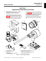
1-1 COMPONENT CHECKLIST OF TYPICAL
SYSTEM (PACKAGE CONTENTS)
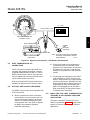
A typical Rosemount Two-Wire In Situ Oxygen
Analyzer should contain the items shown in
Figure 1-1. Record the part number, serial num-
ber, and order number for each component of
your system in the table located on the first
page of this manual. Also, use the product ma-
trix in Table 1-1 to compare your order number
against your unit. The first part of the matrix de-
fines the model. The last part defines the vari-
ous options and features of the analyzer.
Ensure the features and options specified by
your order number are on or included with the
unit.
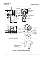
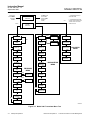
o
HART Communicator
FISHER-ROSEMOUNT
TM
MAN 4275A00
English
October 1994
7
2
3
1
8
6
26020036
4
5
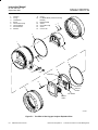
1. Instruction Bulletin
2. Model 3081 Transmitter
3. Oxygen Probe
4. Adapter Plate with mounting hardware
and gasket (Optional)
5. Infrared Remote Control (IRC) (Optional)
6. Reference Air Set (Optional)
7. HART
®
Communicator Package (Optional)
8. Pipe Mounting Kit (Optional)
Figure 1-1. Typical System Package
1

Instruction Manual
IB-106-3081 Rev. 1.5
September 2002
1-2 Description and Specifications Rosemount Analytical Inc. A Division of Emerson Process Management
Model 3081FG
Table 1-1. Product Matrix
3081FG High Temperature Oxygen Flue Gas Analyzer
High Temperature Analyzer - Instruction Book
Code Sensing Probe Length
1 20 in. (508 mm) probe, 1/4 in. tube fittings
2 26 in. (660 mm) probe, 1/4 in. tube fittings
3 34.625 in. (880 mm) probe, 1/4 in. tube fittings
Code Probe Outer Tube Material - Maximum Operating Temperature
1 Alumina - 2912°F (1600°C) maximum - 1.25 NPT mounting
2 Inconel 600 - 1832°F (1000°C) maximum - 1.25 NPT mounting
Code Mounting Adapter - Stack Side
0 No adapter plate required uses 1.25 NPT
("0" must also be chosen under "Mounting Adapter" below)
1 New flanged installation - Square weld plate with studs (matches "Mounting Adapter" below)
2 Model 450 mounting ("4" must also be chosen under "Mounting Adapter" below)
3 Competitor's Mount ("5" must also be chosen under "Mounting Adapter" below)
Code Mounting Adapter - Probe Side
0 No adapter plate
1 ANSI 2 in. 150 lb flange to 1.25 NPT adapter
(6 in. dia. flange, 4.75 in. BC with 4 x 0.75 in. dia. holes)
2 DIN to 1.25 NPT adapter (184 mm flange, 145 mm BC with 4 x 18 mm dia. holes)
3 JIS to 1.25 NPT adapter (155 mm flange, 130 mm BC with 4 x 13 mm dia. holes)
4 Model 450 to 1.25 NPT adapter
5 Competitor's mounting flange
Code Electronics & Housing - Intrinsically Safe, NEMA 4X, IP65
1 3081 Electronics (Hart-compatible) - CENELEC EEx ia IIC T5
2 3081 Electronics (Hart-compatible) - CSA pending
3 3081 Electronics (Hart-compatible) - FM Class I, Div. I, Groups B,C,D
Code Housing Mounting
0 Surface or wall mounting
1 1/2 to 2 in. pipe mounting
Code Communications
0 No remote control
1 Infrared Remote Control (IRC)
(LCD display through cover window)
Code Calibration Accessories
1 No hardware
2 Calibration and reference air flowmeters and refer-
ence air pressure regulator
Code Armored Cable Length
00 No cable
11 20 ft (6 m)
12 40 ft (12 m)
13 60 ft (18 m)
14 80 ft (24 m)
15 100 ft (30 m)
16 150 ft (45 m)
17 200 ft (61 m)
18 300 ft (91 m)
19 400 ft (122 m)
20 500 ft (152 m)
3081FG2100111211 Example

Instruction Manual
IB-106-3081 Rev. 1.5
September 2002
Rosemount Analytical Inc. A Division of Emerson Process Management Description and Specifications 1-3
Model 3081FG
1-2 SYSTEM OVERVIEW
a. Scope
This Instruction Bulletin is designed to sup-
ply details needed to install, start up, oper-
ate, and maintain the Rosemount Two-Wire
In Situ Oxygen Analyzer. The analyzer con-
sists of an oxygen probe and Model 3081
Transmitter. The signal conditioning elec-
tronics of the Model 3081 Transmitter out-
puts a 4-20 mA signal representing an O
2
value. An infrared remote control (IRC) al-
lows access to setup, calibration, and diag-
nostics. This same information, plus
additional details, can be accessed with the
HART Model 275 handheld communicator
or Asset Management Solutions (AMS)
software.
b. System Description
The Rosemount Two-Wire In Situ Oxygen
Analyzer is designed to measure the net
concentration of oxygen in an industrial pro-
cess; i.e., the oxygen remaining after all fu-
els have been oxidized. The oxygen probe
is permanently positioned within an exhaust
duct or stack and performs its task without
the use of a sampling system. The Model
3081 Transmitter is mounted remotely and
conditions the oxygen probe outputs.
The equipment measures oxygen percent-
age by reading the voltage developed
across an electrochemical cell, which con-
sists of a small yttria-stabilized, zirconia
disc. Both sides of the disc are coated with
porous metal electrodes. The millivolt output
voltage of the cell is given by the following
Nernst equation:
EMF = KT log10(P1/P2) + C
Where:
1. P
2
is the partial pressure of the oxygen
in the measured gas on one side of the
cell.
2. P
1
is the partial pressure of the oxygen
in the reference air on the opposite side
of the cell.
3. T is the absolute temperature.
4. C is the cell constant.
5. K is an arithmetic constant.
NOTE
For best results, use clean, dry, in-
strument air (20.95% oxygen) as the
reference air.
NOTE
The probe uses a Type B thermocou-
ple to measure the cell temperature.
When the cell is at 550°C to 1600°C
(1022°F to 2912°F) and there are unequal
oxygen concentrations across the cell, oxy-
gen ions will travel from the high oxygen
partial pressure side to the low oxygen par-
tial pressure side of the cell. The resulting
logarithmic output voltage is approximately
50 mV per decade.
The output is proportional to the inverse
logarithm of the oxygen concentration.
Therefore, the output signal increases as
the oxygen concentration of the sample gas
decreases. This characteristic enables the
Rosemount Two-Wire In Situ Oxygen Ana-
lyzer to provide exceptional sensitivity and
accuracy at low oxygen concentrations.
Oxygen analyzer equipment measures net
oxygen concentration in the presence of all
the products of combustion, including water
vapor. Therefore, it may be considered an
analysis on a "wet" basis. In comparison
with older methods, such as the portable
apparatus, which provides an analysis on a
"dry" gas basis, the "wet" analysis will, in
general, indicate a lower percentage of oxy-
gen. The difference will be proportional to
the water content of the sampled gas
stream.
c. System Configuration
The equipment discussed in this manual
consists of two major components: the oxy-
gen probe and the Model 3081 Transmitter.
Oxygen probes are available in three length
options, providing in situ penetration appro-
priate to the size of the stack or duct. The
options on length are 20 in. (508 mm), 26 in.
(660 mm), or 34.625 in. (880 mm).
1

Instruction Manual
IB-106-3081 Rev. 1.5
September 2002
1-4 Description and Specifications Rosemount Analytical Inc. A Division of Emerson Process Management
Model 3081FG
The Model 3081 Transmitter is a two-wire
transmitter providing an isolated output, 4-
20 mA, that is proportional to the measured
oxygen concentration. A customer-supplied
24 VDC power source is required to simul-
taneously provide power to the electronics
and a 4-20 mA signal loop. The transmitter
accepts millivolt signals generated by the
probe and produces the outputs to be used
by other remotely connected devices. The
output is an isolated 4-20 mA linearized
current.
d. System Features
1. The cell output voltage and sensitivity
increase as the oxygen concentration
decreases.
2. High process temperatures eliminate
the need for external cell heating and
increase cell accuracy.
3. HART communication is standard. To
use the HART capability, you must
have either:
(a) HART Model 275 Communicator
(b) Asset Management Solutions
(AMS) software for the PC
4. Easy probe replacement due to the
light-weight, compact probe design.
5. Remote location of the Model 3081
Transmitter removes the electronics
from high temperature or corrosive
environments.
6. Power is supplied to the electronics
through the 4-20 mA line for intrinsic
safety (IS) purposes.
7. Infrared remote control (IRC) allows
interfacing without exposing the
electronics.
8. An operator can operate and diagnos-
tically troubleshoot the Two-Wire In
Situ Oxygen Analyzer in one of two
ways:
(a) Infrared Remote Control. The IRC
allows access to fault indication
menus on the Model 3081 Trans-
mitter LCD display. Calibration can
be performed from the IRC keypad.
(b) Optional HART Interface. The
Two-Wire In Situ Oxygen Ana-
lyzer’s 4-20 mA output line trans-
mits an analog signal proportional
to the oxygen level. The HART
output is superimposed on the 4-20
mA output line. This information
can be accessed through the
following:
1 Rosemount Model 275 Hand-
held Communicator - The
handheld communicator re-
quires Device Description
(DD) software specific to the
Two-Wire In Situ Oxygen
Analyzer. The DD software
will be supplied with many
Model 275 units but can also
be programmed into existing
units at most Fisher-
Rosemount service offices.
See Section 4, HART/AMS,
for additional HART
information.
2 Personal Computer (PC) -
The use of a personal com-
puter requires AMS software
available from Fisher-
Rosemount.
9. Selected Distributed Control Systems -
The use of distributed control systems
requires input/output (I/O) hardware
and AMS Security codes are provided
to (by infrared remote control) prevent
unintended changes to analyzers adja-
cent to the one being accessed.
10. A calibration check procedure is pro-
vided to determine if the Rosemount
Two-Wire In Situ Oxygen Analyzer is
correctly measuring the net oxygen
concentration in the industrial process.

Instruction Manual
IB-106-3081 Rev. 1.5
September 2002
Rosemount Analytical Inc. A Division of Emerson Process Management Description and Specifications 1-5
Model 3081FG
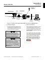
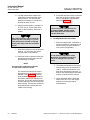
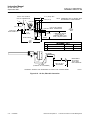
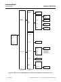
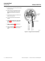
TWO-WIRE IN SITU
OXYGEN ANALYZER
TERMINATION IN
CONTROL ROOM
24 VDC
POWER
SUPPLY
+
INTRINSIC
SAFETY
BARRIER
(OPTIONAL)
26020037
ASSET MANAGEMENT
SOLUTIONS
4-20 mA OUTPUT
(TWISTED PAIR)
HART MODEL 275
HAND HELD
INTERFACE
MODEL 3081
TRANSMITTER
OmV
SIGNAL
2
TEMPERATURE
mV SIGNAL
REFERENCE
AIR LINE
CALIBRATION CHECK
GAS LINE
Figure 1-2. Two-Wire In Situ Oxygen Analyzer HART Connections and AMS Application
e. Handling the Analyzer
The probe was specially packaged to pre-
vent breakage due to handling. Do not re-
move the padding material from the probe
until immediately before installation.
It is important that printed circuit
boards and integrated circuits are
handled only when adequate antistatic
precautions have been taken to pre-
vent possible equipment damage.
The oxygen probe is designed for in-
dustrial applications. Treat with care to
avoid physical damage. The probe
contains components made from ce-
ramic, which are susceptible to shock
when mishandled. THE WARRANTY
DOES NOT COVER DAMAGE FROM
MISHANDLING.
f. System Considerations
Prior to installing your Rosemount Two-Wire
In Situ Oxygen Analyzer, make sure you
have all the components necessary to make
the system installation. Ensure all the com-
ponents are properly integrated to make the
system functional.
After verifying that you have all the compo-
nents, select mounting locations and deter-
mine how each component will be placed in
terms of available line voltage, ambient
temperatures, environmental considera-
tions, convenience, and serviceability. Fig-
ure 1-2 shows a typical system wiring. A
typical system installation is illustrated in
Figure 1-3.
1

Instruction Manual
IB-106-3081 Rev. 1.5
September 2002
1-6 Description and Specifications Rosemount Analytical Inc. A Division of Emerson Process Management
Model 3081FG
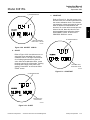
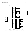
DUCT
STACK
GASES
PRESSURE
REGULATOR
FLOWMETER
OPTIONAL
ADAPTER
PLATE
4-20 mA SIGNAL
26020038
MODEL 3081
TRANSMITTER
OXYGEN
PROBE
INSTRUMENT
AIR SUPPLY
(REFERENCE AIR)
Figure 1-3. Typical System Installation
A source of instrument air is required at the
oxygen probe for reference air use. Since
the Two-Wire In Situ Oxygen Analyzer is
equipped with an in-place calibration fea-
ture, provisions should be made for con-
necting calibration check gas tanks to the
oxygen probe during calibration.
If the calibration check gas bottles are to be
permanently connected, a check valve is
required next to the calibration fittings on
the integral electronics.
This check valve is to prevent breathing of
calibration check gas line and subsequent
flue gas condensation and corrosion. The
check valve is in addition to the stop valve
in the calibration check gas kit.
NOTE
The electronics of the Model 3081
Transmitter is rated NEMA 4X (IP65)
and is capable of operating at tem-
peratures up to 65°C (149°F).
Retain the packaging in which the
Rosemount Two-Wire In Situ Oxygen
Analyzer arrived from the factory in
case any components are to be
shipped to another site. This packag-
ing has been designed to protect the
product.

Instruction Manual
IB-106-3081 Rev. 1.5
September 2002
Rosemount Analytical Inc. A Division of Emerson Process Management Description and Specifications 1-7
Model 3081FG
1-3 SPECIFICATIONS
Net O
2
Range....................................................................... 0 to 25% O
2
Fully Field Selectable via the HART Interface
Lowest Limit................................................................. 0.05% O
2
Highest Limit................................................................ 25.00% O
2
Accuracy .............................................................................. ±1.5% of reading or 0.05% O
2
, whichever is greater
System Response to Calibration Check Gas ...................... Initial response in less than 3 seconds
T90 in less than 10 seconds
PROBE
Lengths ................................................................................ 20 in. (508 mm)
26 in. (660 mm)
34.625 in. (880 mm)
Temperature Limits
Process Temperature Limits........................................ 550° to 1400°C (1022° to 2552°F)
Operation to 1600°C (2912°F) with reduced cell life.
Ambient........................................................................ -40° to 149°C (-40° to 300°F) Ambient
Mounting and Mounting Position ......................................... Vertical or Horizontal
Materials of Construction
Process Wetted Parts
Inner Probe .................................................................. Zirconia
Outer Protection Tube ................................................. Alumina [1600°C (2912°F) limit]
Inconel 600 [1000°C (1832°F) limit]
Probe Junction Box ..................................................... Cast aluminum
Speed of Installation/Withdrawal ......................................... 1 in. (25.4 mm) per minute
Hazardous Area Certification............................................... Intrinsically safe per EN50 014 (1977), clause 1.3(1)
Reference Air Requirement ................................................. 100 ml per minute (0.2 scfh) of clean, dry instrument
air; 1/4 in. tube fittings
Calibration Check Gas Fittings ............................................ 1/4 in. tube fittings
Cabling................................................................................. Two twisted pairs, shielded
(1)
Thermocouple and O
2
probe cell are both unpowered, developing a millivolt emf, and are considered a
“simple apparatus” by certifying agencies.
1

Instruction Manual
IB-106-3081 Rev. 1.5
September 2002
1-8 Description and Specifications Rosemount Analytical Inc. A Division of Emerson Process Management
Model 3081FG
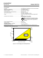
ELECTRONICS
Enclosure....................................................................... IP65 (NEMA 4X), weatherproof, and corrosion-resistant
Materials of Construction ............................................... Low copper aluminum
Ambient Temperature Limits ......................................... -20° to 65°C (-4° to 149°F)
Relative Humidity........................................................... 95% with covers sealed
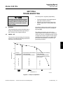
Power Supply and Load Requirements ......................... See Figure 1-4
Inputs (from O
2
Probe)................................................... Two wires - O
2
signal
Two wires - type B thermocouple
Output ............................................................................ One 4-20 mA signal with superimposed digital HART
signal
Hazardous Area Certification......................................... Cenelec EEx ia IIC T4 or T5(2)
NEC Class I Div. I Group B,C,D
Fisher-Rosemount has satisfied all obliga-
tions coming from the European legislation
to harmonize the product requirements in
Europe.
Power Transient Protection ........................................... IEC 801-4
Shipping Weight............................................................. 10 lbs (4.5 kg)
INFRARED REMOTE CONTROL
Power Requirements ..................................................... Three AAA batteries
Hazardous Area Certification......................................... Cenelec EEx ia IIC Class I, Div. I, Group A, B, C, D
(2)
Dependent on ambient temperature limits.
OPERATING
REGION
WITHOUT HART COMMUNICATOR
12.0 VDC 18 VDC 40 VDC @ ZERO LOAD 42.4 VDC
MAXIMUM
LIFT OFF
POWER SUPPLY VOLTAGE
29750007
600
OHMS
@ 42.4
VDC
1848
OHMS
@ 42.4
VDC
1848
1800
1500
1000
500
250
0
LOAD (OHMS)
Figure 1-4. Power Supply and Load Requirements

Instruction Manual
IB-106-3081 Rev. 1.5
September 2002
Rosemount Analytical Inc. A Division of Emerson Process Management Installation 2-1
Model 3081FG
SECTION 2
INSTALLATION
2-1 PRE-INSTALLATION
a. Inspect
Carefully inspect the shipping container for
any evidence of damage. If the container is
damaged, notify the carrier immediately.
b. Packing List
Confirm that all items shown on the packing
list are present. Notify Rosemount Analytical
immediately if items are missing.
Before installing this equipment, read
the “Safety instructions for the wiring
and installation of this apparatus” at
the front of this Instruction Bulletin.
Failure to follow the safety instruc-
tions could result in serious injury or
death.
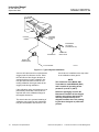
2-2 MECHANICAL INSTALLATION
Avoid installation locations near
steam soot blowers.
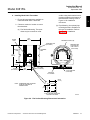
a. Locating Oxygen Probe
1. The location of the oxygen probe in
the stack or flue is important for maxi-
mum accuracy in the oxygen analyzing
process. The probe must be positioned
so the gas it measures is representa-
tive of the process. Best results are
normally obtained if the probe is posi-
tioned near the center of the duct (40-
60% insertion). Longer ducts may re-
quire several analyzers since the O
2
can vary due to stratification. A point
too near the wall of the duct, or the in-
side radius of a bend, may not provide
a representative sample because of
the very low flow conditions. The
sensing point should be selected so
the process gas temperature falls
within a range of 550° to 1600°C
(1022° to 2912°F). Figure 2-1 provides
mechanical installation references.
2. Check the flue or stack for holes and
air leakage. The presence of this con-
dition will substantially affect the accu-
racy of the oxygen reading. Therefore,
either make the necessary repairs or
install the probe upstream of any
leakage.
3. Ensure the area is clear of internal and
external obstructions that will interfere
with installation and maintenance ac-
cess to the probe. Allow adequate
clearance for probe removal (Figure
2-1).
b. Installing Oxygen Probe
The probe was specially packaged to
prevent breakage due to handling. Do
not remove the padding material from
the probe until immediately before
installation.
1. Ensure all components are available to
install the probe.
NOTE
Leave the probe inner protective cover
in place until installation. This is re-
quired to protect the ceramic cell dur-
ing movement.
2. If using an optional adapter plate
(Figure 2-2) or an optional mounting
flange (Figure 2-3), weld or bolt the
component onto the duct. The through
hole in the stack or duct wall and re-
fractory material must be 2 in. (50.8
mm) diameter, minimum.
2

Instruction Manual
IB-106-3081 Rev. 1.5
September 2002
2-2 Installation Rosemount Analytical Inc. A Division of Emerson Process Management
Model 3081FG
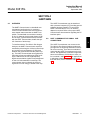
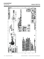
O
O
1.25 NPT PROCESS
CONNECTION
SIDE VIEW
BOTTOM VIEW
INSTALL WITH PORT AT
THE BOTTOM
3/4 NPT
CONDUIT
PORT
DIM “A”
7.1 (180)
4.1
(109)
DIM “B”
(REMOVAL ENVELOPE)
1.1
(29)
1.8
(49)
1/4 TUBE FITTING
(CALIBRATION
CHECK GAS PORT)
1/4 TUBE FITTING
(REFERENCE
AIR PORT)
REFERENCE
AIR VENT
FRONT VIEW
NOTE: DIMENSIONS ARE IN INCHES WITH
MILLIMETERS IN PARENTHESES.
TABLE 1. INSTALLATION (REMOVAL)
PROBE
20 IN.
26 IN.
34.625 IN.
DIM “A”
20 (508)
26 (660)
34.625 (880)
DIM “B”
31 (787)
37 (940)
46 (1170)
3.0
(77)
29750001
Figure 2-1. Probe Installation Details
Page is loading ...
Page is loading ...
Page is loading ...
Page is loading ...
Page is loading ...
Page is loading ...
Page is loading ...
Page is loading ...
Page is loading ...
Page is loading ...
Page is loading ...
Page is loading ...
Page is loading ...
Page is loading ...
Page is loading ...
Page is loading ...
Page is loading ...
Page is loading ...
Page is loading ...
Page is loading ...
Page is loading ...
Page is loading ...
Page is loading ...
Page is loading ...
Page is loading ...
Page is loading ...
Page is loading ...
Page is loading ...
Page is loading ...
Page is loading ...
Page is loading ...
Page is loading ...
Page is loading ...
Page is loading ...
Page is loading ...
Page is loading ...
Page is loading ...
Page is loading ...
Page is loading ...
Page is loading ...
Page is loading ...
Page is loading ...
Page is loading ...
Page is loading ...
Page is loading ...
Page is loading ...
Page is loading ...
Page is loading ...
Page is loading ...
Page is loading ...
Page is loading ...
Page is loading ...
Page is loading ...
Page is loading ...
Page is loading ...
Page is loading ...
Page is loading ...
Page is loading ...
-
 1
1
-
 2
2
-
 3
3
-
 4
4
-
 5
5
-
 6
6
-
 7
7
-
 8
8
-
 9
9
-
 10
10
-
 11
11
-
 12
12
-
 13
13
-
 14
14
-
 15
15
-
 16
16
-
 17
17
-
 18
18
-
 19
19
-
 20
20
-
 21
21
-
 22
22
-
 23
23
-
 24
24
-
 25
25
-
 26
26
-
 27
27
-
 28
28
-
 29
29
-
 30
30
-
 31
31
-
 32
32
-
 33
33
-
 34
34
-
 35
35
-
 36
36
-
 37
37
-
 38
38
-
 39
39
-
 40
40
-
 41
41
-
 42
42
-
 43
43
-
 44
44
-
 45
45
-
 46
46
-
 47
47
-
 48
48
-
 49
49
-
 50
50
-
 51
51
-
 52
52
-
 53
53
-
 54
54
-
 55
55
-
 56
56
-
 57
57
-
 58
58
-
 59
59
-
 60
60
-
 61
61
-
 62
62
-
 63
63
-
 64
64
-
 65
65
-
 66
66
-
 67
67
-
 68
68
-
 69
69
-
 70
70
-
 71
71
-
 72
72
-
 73
73
-
 74
74
-
 75
75
-
 76
76
-
 77
77
-
 78
78


Emerson 3081FG 2-Wire In Situ O2 Analyzer (550° to 1600°C)-Rev 1.5 User manual
- Category
- Oxygen Equipment
- Type
- User manual
- This manual is also suitable for
Ask a question and I''ll find the answer in the document
Finding information in a document is now easier with AI
Related papers
-
Rosemount 3081FG Owner's manual
-
-
-
Emerson oxymitterdr hazardous area in-siu oxygen probe User manual
-
-
-
-
-
-
Other documents
-
 Fisher-Rosemount 00275-8026-0001 User manual
-
-
ETS 850 User manual
-
-
-
-
-
-
-
